EP2686514B1 - Plaque d'usure intégrée et procédé - Google Patents
Plaque d'usure intégrée et procédé Download PDFInfo
- Publication number
- EP2686514B1 EP2686514B1 EP11801279.8A EP11801279A EP2686514B1 EP 2686514 B1 EP2686514 B1 EP 2686514B1 EP 11801279 A EP11801279 A EP 11801279A EP 2686514 B1 EP2686514 B1 EP 2686514B1
- Authority
- EP
- European Patent Office
- Prior art keywords
- drill pipe
- standard weight
- external diameter
- wear pad
- tubular member
- Prior art date
- Legal status (The legal status is an assumption and is not a legal conclusion. Google has not performed a legal analysis and makes no representation as to the accuracy of the status listed.)
- Not-in-force
Links
Images


Classifications
-
- B—PERFORMING OPERATIONS; TRANSPORTING
- B23—MACHINE TOOLS; METAL-WORKING NOT OTHERWISE PROVIDED FOR
- B23K—SOLDERING OR UNSOLDERING; WELDING; CLADDING OR PLATING BY SOLDERING OR WELDING; CUTTING BY APPLYING HEAT LOCALLY, e.g. FLAME CUTTING; WORKING BY LASER BEAM
- B23K31/00—Processes relevant to this subclass, specially adapted for particular articles or purposes, but not covered by any single one of main groups B23K1/00 - B23K28/00
- B23K31/02—Processes relevant to this subclass, specially adapted for particular articles or purposes, but not covered by any single one of main groups B23K1/00 - B23K28/00 relating to soldering or welding
-
- B—PERFORMING OPERATIONS; TRANSPORTING
- B23—MACHINE TOOLS; METAL-WORKING NOT OTHERWISE PROVIDED FOR
- B23K—SOLDERING OR UNSOLDERING; WELDING; CLADDING OR PLATING BY SOLDERING OR WELDING; CUTTING BY APPLYING HEAT LOCALLY, e.g. FLAME CUTTING; WORKING BY LASER BEAM
- B23K20/00—Non-electric welding by applying impact or other pressure, with or without the application of heat, e.g. cladding or plating
- B23K20/12—Non-electric welding by applying impact or other pressure, with or without the application of heat, e.g. cladding or plating the heat being generated by friction; Friction welding
- B23K20/129—Non-electric welding by applying impact or other pressure, with or without the application of heat, e.g. cladding or plating the heat being generated by friction; Friction welding specially adapted for particular articles or work
-
- E—FIXED CONSTRUCTIONS
- E21—EARTH OR ROCK DRILLING; MINING
- E21B—EARTH OR ROCK DRILLING; OBTAINING OIL, GAS, WATER, SOLUBLE OR MELTABLE MATERIALS OR A SLURRY OF MINERALS FROM WELLS
- E21B17/00—Drilling rods or pipes; Flexible drill strings; Kellies; Drill collars; Sucker rods; Cables; Casings; Tubings
- E21B17/10—Wear protectors; Centralising devices, e.g. stabilisers
- E21B17/1085—Wear protectors; Blast joints; Hard facing
-
- Y—GENERAL TAGGING OF NEW TECHNOLOGICAL DEVELOPMENTS; GENERAL TAGGING OF CROSS-SECTIONAL TECHNOLOGIES SPANNING OVER SEVERAL SECTIONS OF THE IPC; TECHNICAL SUBJECTS COVERED BY FORMER USPC CROSS-REFERENCE ART COLLECTIONS [XRACs] AND DIGESTS
- Y10—TECHNICAL SUBJECTS COVERED BY FORMER USPC
- Y10T—TECHNICAL SUBJECTS COVERED BY FORMER US CLASSIFICATION
- Y10T29/00—Metal working
- Y10T29/49—Method of mechanical manufacture
- Y10T29/49826—Assembling or joining
Definitions
- Drilling operations subject drill pipe to a variety of stresses, frictional forces, and environments. During directional drilling, the drill pipe will bend, resulting in well bore contact. As a result, the center portion of the drill pipe will wear and ultimately lead to failure or premature replacement of the drill pipe.
- the terms drill pipe and standard weight drill pipe are referred to interchangeably herein.
- wear pads may be installed at select locations on the drill pipe.
- Wear pads presently used with standard weight drill pipe are generally cylindrical, sleeve-like devices installed on the exterior surface of the drill pipe. Many of these sleeve-like wear pads clamp to the exterior surface of the drill pipe. Unfortunately, clamp style wear pads tend to slip leaving target wear prone areas exposed. Additionally, the necessary installation and subsequent maintenance of clamp style wear pads will slow down drilling operations.
- Standard weight drill pipe has mechanical properties such as flexibility, toughness, and fatigue resistance, among others that make it particularly suitable for use in the center of a drill string.
- a particular drill string may include a variety of components, such as drill collars and intermediate weight members, which are typically used between the drill bit and the drill pipe in the drill string. These components are made of thicker, stiffer, heavier materials than standard weight drill pipe. Accordingly, drill collars and intermediate weight members are used as a transition from drill bit to drill pipe in order to reduce impact loads on the drill pipe. Since at least 1960, drill collars and intermediate weight members have been available with machined wear pads. However, drill collars and intermediate weight members do not have the stated mechanical properties of drill pipe. Additionally, these heavier components use a greater amount of limited drill rig power and lack flexibility. Other limitations prevent drill collars and intermediate weight members from functioning as a feasible alternative to drill pipe and the wear pads mentioned above.
- US 3,484,122 discloses a drill pipe protector comprising a sleeve having thicker wall sections and a larger diameter than the standard pipe.
- the present invention provides an improved standard weight drill pipe.
- the improved drill pipe includes an integral wear pad suitable for shielding the drill pipe from erosion during directional drilling processes.
- the integral wear pad is centrally located on the drill pipe; however, the position of the integral wear pad may vary.
- the improved drill pipe may have one or more integral wear pads.
- the present invention provides methods for manufacturing standard weight drill pipe having an integral wear pad.
- a first upset is formed on the first end of a first length of standard weight drill pipe.
- a second upset is formed on the first end of a second length of standard weight drill pipe.
- the first and second lengths of drill pipe are joined by integrally bonding the first and second upsets to one another thereby yielding a single drill pipe having an integral wear pad corresponding to the first and second upsets.
- the method of the present invention forms first and second upset ends on separate drill pipe stock.
- the method also provides a section of drill pipe having an outer diameter and cross-sectional thickness corresponding to the first and second upsets.
- the short section of drill pipe is bonded between the first and second upsets to produce a single length of drill pipe having an integral wear pad corresponding to the first and second upsets and the short section of drill pipe,
- the method of the present invention forms first and second upsets on separate drill pipe stock.
- the respective upsets are suitably formed for connection to a conventional tool joint pin and box.
- a conventional tool joint pin is secured to one drill pipe while a box is secured to the other drill pipe. Thereafter, the tool joint pin and box are threadedly secured together. Subsequently, the joints formed by the tool joint pin and box are welded to provide a drill pipe having an integral wear pad.
- hard banding material may be applied to the wear pad.
- the present invention provides a method for forming wear resistant drill pipe.
- the present invention initially forms first and second upsets on separate drill pipe stock.
- the method also provides a short section of pipe with a wear pad formed between each end of the short section, wherein the wear pad has a larger outer diameter than the first and second upsets and the separate drill pipes.
- the method provides the short section of pipe with each end having an outer diameter and cross-sectional thickness corresponding to the first and second upsets.
- the short section of pipe is bonded between the first and second upsets to produce a single length of drill pipe having an integral wear pad formed into the short section of pipe.
- the present invention provides a method of manufacturing wear resistant drill pipe for use in the down-hole environment.
- This method provides two stock components of standard weight drill pipe with each drill pipe having a first external diameter.
- the methods form a first upset on at least one end of the first standard weight drill pipe and a second upset on at least one end of the second standard weight drill pipe.
- the upsets have a second external diameter.
- the external diameter of the second upset is substantially the same as the second external diameter of the first upset.
- the method also provides a third tubular member comprising a wear pad having a third external diameter, a first end having a fourth external diameter, and a second end having an fourth external diameter, wherein the fourth external diameters of the first and second ends of the third tubular member are substantially equal to one another and substantially equal to the second external diameters of the first and second upsets.
- the third external diameter of the wear pad is greater than the first external diameters of the first and second standard weight drill pipes ends and the second external diameters of the first and second upsets.
- the wear pad is located between the first and second ends of the third tubular member.
- the first upset is joined to the first end of the third tubular member.
- the method of joining maintains the first standard weight drill pipe substantially concentric with the third tubular member.
- the method joins the second upset to the second end of the third tubular member.
- the method of joining maintains the second standard weight drill pipe substantially concentric with the third tubular member and the first standard weight drill pipe.
- standard weight drill pipe refers to drill pipe manufactured to American Petroleum Institute (API) Specification 5DP.
- Standard weight drill pipe satisfying this standard may comprise a variety of metals.
- a typical standard weight drill pipe will be manufactured from American Iron and Steel Institute (AISI) 4127 4130 grade steel.
- Drill pipe satisfying API Specification 5DP may have a range of wall thicknesses.
- the maximum wall thickness (D) of standard weight drill pipe satisfying API Specification 5DP will be less than approximately 2.54 cm (1.000 inches) but greater than 0.635 cm (0.250 inches).
- standard weight drill pipe differs significantly from intermediate and heavy weight drill pipes, and drill collars, which typically have wall thicknesses of 2.54 cm (1.000 inch) or greater.
- a standard prior art drill pipe 2 includes first and second ends 4, 6 suitable for securing tools or one drill pipe 2 to another.
- standard weight drill pipe will flex during directional drilling operations. During such operations, central region 11 will commonly contact the well bore wall or the casing. As a result, central region 11 will experience excessive wear.
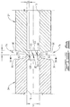
- Drill pipe 10 includes a drill pipe body 16 having an internal bore 18 extending the length thereof. Internal bore 18 also passes through the region defined by wear pad 26.
- Drill pipe 10 is suitable for standard or conventional use within the downhole drilling environment. As such, drill pipe 10 may be modified at either end for inclusion within a pipe string or for attachment of various tools or tool joints. Such modifications are well known in the art and will not be discussed herein. Rather, the following discussion will focus on the improvement provided by integral wear pad 26 and methods for producing a standard weight drill pipe having an integral wear pad.
- the present invention provides an integral wear pad 26.
- at least one wear pad 26 will be located within central region 11 of drill pipe 10.
- One centrally located wear pad 26 will protect drill pipe 10 from, excessive wear during drilling.
- the present disclosure also contemplates a drill pipe 10 having a plurality of integral wear pads 26.
- the preferred embodiment of wear pad 26 includes at least a pair of first tapers 32.
- tapers 32 provide a transition from external diameter (A) of drill pipe body 16 to external diameter (B) of wear pad 26.
- the optional first transitional tapers 32 reduce snags during drilling.
- the external diameter (B) of wear pad 26 is at least 1.27 cm (0.500 inches) greater than the diameter (A) of drill pipe body 16. In this configuration, wear pad 26 will shield the thinner walled drill pipe body 16 from damage occurring from borehole contact.
- the additional diameter thickness provided by external diameter (B) will preclude contact of drill pipe body 16 with a borehole wall during drilling.
- Diameter (A) of drill pipe body 16 will be within the range specified by API Specification 5DP. Typically, diameter (A) will be between 8.89 cm and 16.83 cm (3.500 and 6.625 inches) and will be generally consistent along drill pipe body 16 unless modified to accept a tool joint or other similar connection as known to those skilled in the art.
- wear pad 26 further includes a surface layer 40 providing increased wear resistance.
- Layer 40 is preferably a sacrificial material commonly adhered to the circumferential surface of tool joints. As such, the types of sacrificial materials and methods for applying the same are well known to those skilled in the art. The preferred sacrificial material will not damage the casing in the well bore. Layer 40 is commonly known in the industry as a hardbanding layer 40. As shown in Figure 5 , layer 40 does not necessarily cover the entirety of wear pad 26.
- hardbanding layer 40 Commonly known as a hardbanding layer or wear surfacing layer to those skilled in the art, inclusion of hardbanding layer 40 on the circumferential surface of wear pad 26 will further enhance the life of drill pipe 10.
- Materials suitable for use as a hardbanding layer 40 include but are not necessarily limited to heat treatable tool steel wire such as DURABANDTM or TUFFBANDTM, available from Postle Industries, Inc., P.O. Box 42037, Cleveland, Ohio, United States.
- hardbanding layer 40 will be hardened steel having a hardness rating greater than that of drill pipe 10.
- hardbanding layer 40 will preferably have a Rockwell C-scale (HRC) hardness rating of about 45 HRC to about 55 HRC.
- HRC Rockwell C-scale
- hardbanding layer 40 will be about 0.318 cm to about 0.478 cm (about 0.125 inches to about 0.188 inches) in thickness.
- the inclusion of hardbanding layer 40 on the circumferential surface of wear pad 26 increases the overall external diameter (B) by twice the thickness of the layer 40.
- total wear pad 26 external diameter (B) may range from about 10.795 cm to about 21.273 cm (about 4.250 inches to about 8.375 inches), including hardbanding layer 40.
- the cross-sectional thickness of wear pad 26, including hardbanding layer 40 may range from about 2.858 cm to about 4.288 cm (about 1.125 inches to about 1.688 inches).
- overall external diameter (B) may range from about 10.16 cm to 20.32 cm (about 4.000 inches to about 8.000 inches).
- the wear pad cross-sectional thickness (E) without hardbanding layer 40 may range from about 2.54 cm to about 3.81 cm (about 1.000 inch to about 1.500 inches).
- Integral wear pad 26 preferably comprises a redistributed portion of the substrate material of the standard weight drill pipe body 16.
- drill pipe 10 with integral wear pad 26 exhibits a refined metallurgical grain structure thereby providing wear pad 26 with mechanical properties at least corresponding to a conventional drill pipe lacking integral wear pad 26.
- the metallurgical grai structure of drill pipe 10 throughout the transition from the external diameter (A) of drill pipe body 16 to the external diameter (B) of wear pad 26 remains oriented parallel with the profile of the transition.
- the metallurgical nature of wear pad 26 corresponds, for example, to the strength, toughness, flexibility, and fatigue resistance of drill pipe body 16. Inclusion of hardbanding layer 40 on wear pad 26 will not degrade the mechanical properties of drill pipe 10.
- the current invention reduces down time at the well bore site without sacrificing operability.
- the improved drill pipe 10 includes the previously discussed first transitional tapers 32, wear pad 26, hardbanding layer 40, and drill pipe body 16.
- centrally located wear pad 26 will have an overall length (F) of about 5.08 cm to about 60.96 cm (about 2.000 inches to about 24.000 inches) extending between first taper regions 32, i.e. the length (F) of wear pad 26 does not include first taper regions 32.
- the preferred length (F) of wear pad 26 will range from about 25.4 cm to about 35.56 cm (about 10.000 inches to about 14.000 inches).
- each first taper 32 will generally have an axial length ranging from about 1.27 cm to about 15.24 cm (about 0.500 to about 6.000 inches).
- the axial length of first tapers 32 will range from about 5.08 cm to about 10.16 cm (about 2.000 to about 4.000 inches) and have an angular slope of about 15 degrees to about 25 degrees.
- the angular slope of each first taper 32 will preferably have a metallurgical grain structure generally oriented parallel to the angular slope.
- Internal bore 18 passing through drill pipe body 16 also passes through wear pad 26.
- bore 18 has a substantially consistent internal diameter (C) for the entire length of drill pipe 10. Any slight restrictions within the region of wear pad 26 will not degrade performance of drill pipe 10.
- one preferred embodiment of the improved drill pipe 10 includes second transitional tapers 33 and shoulders 35 in addition to the previously discussed first transitional tapers 32, wear pad 26, hardbanding layer 40, and drill pipe body 16.
- Second transitional tapers 33 have an axial length ranging from about 1.27 cm to about 15.24 cm (about 0.500 inches to about 6.000 inches) and an angular slope of about 15 degrees to about 25 degrees.
- Shoulders 35 have an axial length ranging from about 1.27 cm to about 5.06 cm (about 0.500 inches to about 2.000 inches).
- the present invention contemplates drill pipe 10 with a transitional portion, without limitation to a particular shape, from the external diameter (A) of drill pipe body 16 to the external diameter (B) of wear pad 26.
- the metallurgical grain structure of drill pipe 10 will preferably remain oriented parallel to the angular slope of second tapers 33 and profile of shoulders 35.
- the metallurgical grain structure of first tapers 32 will preferably remain oriented parallel to the angular slope of first tapers 32.
- Internal bore 18 passing through drill pipe body 16 also passes through second tapers 33, shoulders 35, first tapers 32, and wear pad 26.
- bore 18 has a substantially consistent internal diameter (C) for the entire length of drill pipe 10. Any slight restrictions within the region of wear pad 26 will not degrade performance of drill pipe 10.
- wear pad 26 may correspond to modified ends of drill pipe body 16 subsequently joined in a manner discussed below to produce the improved drill pipe 10 of the present invention.
- wear pad 26 may correspond to an additional section of tubular pipe 34.
- Tubular pipe 34 also referred to as tubular member 34, will have metallurgical characteristics corresponding to that of drill pipe body 16.
- tubular section 34 provides an integral wear pad 26 as discussed herein.
- the resulting improved drill pipe 10 has an integral wear pad 26 and has metallurgical and mechanical characteristics corresponding to standard weight drill pipe.
- the present invention provides improved standard weight drill pipe 10 including at least one wear pad 26.
- wear pad 26 is centrally located on drill pipe 10.
- one skilled the art can readily attach tools or incorporate drill pipe 10 into a drill string for use in downhole operations.
- the present invention also provides manufacturing processes for preparing a standard weight drill pipe 10 having an integral wear pad 26.
- the method of the current invention forms drill pipe 10 with integral wear pad 26 by concentrically joining two upsets 22, 24 together.
- the method of the present invention provides a drill pipe having an integral wear pad by concentrically incorporating a third tubular member 34 between upsets 22, 24.
- Third tubular member 34 may be, for example, a short section of drill pipe stock or a tube formed from a tool joint pin and box threadedly connected to one another.
- third tubular member 34 may be a short section of tube having a wear pad forged or machined onto the exterior surface of the tube.
- the current invention utilizes a forging process known as upsetting.
- this hot forging process increases the wall thickness and refines the grain structure of the substrate material at the end of the drill pipe 10 in the location of the upset.
- Methods for generating upsets on the ends of drill pipe are well known to those skilled in the art and will not be further discussed herein.
- U.S. Patent No. 4,192,167 For one example of an upsetting process, see U.S. Patent No. 4,192,167 .
- the method of the present invention includes the steps of providing a first upset 22 on an end of a first drill pipe body 16a.
- the method also provides a second upset end 24 on a second drill pipe body 16b.
- an upsetting process increases the wall thickness of the end of a drill pipe by compressing the drill pipe lengthwise, thereby redistributing the substrate material of the drill pipe in the area of the upset at the end of the pipe.
- the resulting upsets 22, 24 have an internal bore 18a substantially consistent with the original bore 18 of drill pipe body 16.
- the internal diameters (C) of bore 18 and bore 18a are substantially the same.
- the external diameter (J) of each upset 22, 24 exceeds the diameter (A) of the drill pipe body 16.
- the method concentrically joins upsets 22 and 24 by welding the respective upsets to one another.
- the resulting drill pipe 10 exhibits consistent mechanical properties throughout wear pad 26 and drill pipe 10.
- the method of the present invention contemplates welding techniques such as, without limitation, friction welding, inertia welding, flash welding, stub welding, and submerged arc welding.
- the preferred embodiment uses an inertia welding process to produce drill pipe 10 with an integral wear pad 26.
- Inertia welding is well known to those skilled in the art as a technique suitable for securing tool joints and other similar components to upsets carried by drill pipe.
- the devices and techniques for inertia welding are well known to those skilled in the art.
- an alternative embodiment also uses a conventional inertia welding process to concentrically join a first end of a third tubular member 34 to either upset 22 or upset 24.
- third tubular member 34 may be a short section of drill pipe stock having an external diameter (B) substantially consistent with the external diameter (J) of upsets 22, 24.
- Third tubular member 34 may also be a short section of tube with a wear pad having an external diameter (B) forged or machined onto the exterior surface of the tube between the ends.
- each end of third tubular member 34 has a cross-sectional thickness and exterior diameter substantially consistent with the respective cross-sectional thickness and exterior diameter of upsets 22, 24.
- the method for incorporating third tubular member 34 into the improved drill pipe 10 may utilize an inertia welding step to secure tubular member 34 to both upsets 22 and 24.
- the method uses inertia welding to secure the first end of tubular member 34 to one upset 22 or 24 and submerged arc welding to secure the second end of tubular member 34 to the remaining upset 22 or 24.
- any welding process capable of providing the desired bond between components while providing the desired metallurgical characteristics will be acceptable for both welding steps.
- the use of a submerged arc welding method for securing tubular member 34 to one of the upsets 22 or 24 preferably includes the step of forming a weld groove 74 between the second end of the tubular member 34 and the unsecured upset 22 or 24 prior to welding.
- Use of weld groove 74 will improve bond integrity between the welded components.
- step 88 is formed using separate reaming processes that extend lengthwise throughout the bore 18 of drill pipe stock 16 and tubular member 34. These reaming steps may occur at anytime before or during the manufacture of improved drill pipe 10.
- the reaming process stops short a length (H) from inlet 80 within drill pipe stock 16 corresponding to the end defined by the unsecured upset 22 or 24.
- the reaming process stops short a length (H) from the inlet 80 within the second end of tubular member 34.
- length (H) defines the axial length of each step 88.
- a radius 92 is machined into the faces 84 of the second end of tubular member 34 and the unsecured upset 22 or 24. Subsequently, the faces 84 of the second end of tubular member 34 and the unsecured upset 22 or 24 machined to provide bevels 96 intersecting each radius 92 at an angle between about 15 degrees to about 20 degrees from each face 84. Subsequently abutting together the tubular member 34 concentric with the unsecured upset 22 or 24 provides a weld groove 74 with a landing 100. Steps 88, each radius 92, and each bevel 96 define weld groove 74.
- Each face 84 is defined by a cross-section taken perpendicular to the axis of each bore 18.
- Each step 88 has a height (G) extending inwardly from the inner surface of each bore 18, and a length (H) extending from each inlet 80 into each bore 18.
- the height (G) of step 88 is between about 0.159 cm to about 0.476 cm (about 0.0625 inches to about 0.1875 inches) and the length (H) is between about 0.476 cm to about 0.794 cm (about 0.1875 inches to about 0.3125 inches).
- step 88 For a length (H) at each inlet 80, the height (G) of step 88 provides an internal diameter between about 0.318 cm to about 0.953 cm (about 0.125 inches to about 0.375 inches) less than the finished internal diameter (C) of bore 18.
- step 88 is machined by reaming out each bore 18 to internal diameter (C) beginning at an end of bore 18 opposite inlet 80 and stopping a distance equal to length (H) from each inlet 80. Machining step 88 in this fashion requires bore 18 to have an unfinished internal diameter smaller than the finished internal diameter (C) by at least two times height (G). In this manner, reaming bore 18 out as stated above will leave step 88 having height (G) and length (H) around the inner circumference of bore 18.
- weld groove 74 facilitates the application of a uniform weld throughout the cross-sectional thickness of each face 84.
- landing 100 is preferably removed by finish reaming bore 18 to internal diameter (C).
- the method also preheats the third tubular member 34 and unsecured upset 22 or 24 to a temperature between about 177°C to about 232°C (about 350 degrees Fahrenheit to about 450 degrees Fahrenheit) prior to application of the weld to the weld groove 74.
- the method applies a mist to each bore 18.
- first drill pipe body 16a is secured in a jig which precludes rotational movement thereof while second drill pipe body 16b is mounted to a mandrel or other suitable support within the inertia welding device.
- Drill pipe bodies 16a, 16b are mounted such that upsets 22 and 24 are opposing and concentric with one another.
- upsets 22 and 24 are preferably brought together to ensure direct alignment thereof and any necessary adjustments to achieve direct alignment carried out.
- the inertia welding machine rotates one drill pipe body 16 and moves upset 24 into direct contact with upset 22. The rotational rate and pressure applied by the inertia welding machine will generate sufficient heat to weld upset 22 to upset 24.
- the resulting weld is a homogeneous, solid state weld having consistent characteristics from the internal bore 18a to the external surface of the resulting wear pad 26.
- the resulting wear pad 26 has dimensions corresponding generally to the original upsets 22 and 24.
- Suitable inertia welders for practicing this embodiment include, but are not limited to, inertia welder model numbers 300BX and 400BX sold by Manufacturing Technology, Inc., 1702 West Washington, South Bend, Indiana 46628, United States.
- Force constants, rotational rates, and weld pressures may vary with different models of inertia welders and with different inertia welders of the same model.
- the force constant, or WK 2 for producing the inertia weld may range from about 45,560 on 200 cm 2 (31 square inches) of weld to about 8,560 on 38.7 cm 2 (6 square inches) of weld.
- the rotational rate of drill pipe body 16 may range from about 757 revolutions per minute for 200 cm 2 (31 square inches) of weld to about 778 revolutions per minute for 38.7 cm 2 (6 square inches) of weld.
- the inertia welder may have weld pressure on upset 24 carried by drill pipe body 16b against upset 22 carried by drill pipe body 16a of about 13.78 kg/cm 2 (about 196 pounds per square inch) for 38.7 cm 2 (6 square inches) of weld to about 69.4 kg/cm 2 (about 987 pounds per square inch) for 200 cm 2 (31 square inches) of weld. More preferably, the pressure of the inertia welding process will forge from about 48.2 kg/cm 2 (about 686 pounds per square inch) for 38.7 cm 2 (6 square inches) of weld to about 243 kg/cm 2 (about 3,456 pounds per square inch) for 200 cm 2 (31 square inches) of weld.
- bore 18a is optionally reamed out to ensure a substantially consistent internal bore 18 passing through drill pipe 10.
- the step of reaming out the area corresponding to the welded upsets 22, 24 removes any excess slag produced by the welding step.
- the external diameter of wear pad 26 may optionally be machined to provide a smooth, generally consistent external diameter (B).
- the method of the present invention further heat treats the resulting drill pipe 10.
- the heat treating steps encompass the entire length of drill pipe 10 and eliminate any heat affected zones formed during the welding operations.
- the heat treating steps produce a hardness generally corresponding to the hardness of a tool joint, i.e. a hardness ranging from about 20 HRC to about 38 HRC.
- the preferred heat treating process includes the following steps: (a) austenitizing at a temperature of about 899°C (about 1650 degrees Fahrenheit); (b) water quenching to ambient temperature, or about 22°C (about 72 degrees Fahrenheit); and, (c) tempering at a temperature ranging from about 566 to 649°C (about 1050 to 1200 degrees Fahrenheit).
- drill pipe 10 now with integral wear pad 26, is ready for further modification as required for use in the downhole environment.
- the preferred embodiment places a conventional upset (not shown) for the connection of tool joints (not shown) on each end of drill pipe 10 and adds the optional hardbanding layer 40 to wear pad 26.
- hardbanding is applied to upsets 22 and 24 after the step of joining the upsets to one another.
- hardbanding layer 40 is applied to tubular member 34 prior to welding member 34 between upsets 22 and 24.
- the step of adding the hardbanding material may occur at any convenient time during the manufacturing process. Additionally, the life of drill pipe 10 may be extended by applying or re-applying hardbanding in the field.
- this step requires the welding of hardened circumferential tool steel wire bands to the outer circumferential surface of wear pad 26.
- a welding process such as Metal Inert Gas (MIG) welding will be used to secure the hardbanding material to wear pad 26.
- MIG Metal Inert Gas
- first outer end 26a and second outer end 26b of wear pad 26 will each receive hardbanding.
- the method of the present invention includes steps for producing drill pipe 10 with integral wear pad 26 formed from a tool joint pin and box.
- This embodiment includes the step of forming a first upset 22 on a first drill pipe body 16a.
- This embodiment also forms a second upset 24 on a second drill pipe body 16b.
- upsets 22 and 24 are suitably formed for connection to a conventional tool joint pin 68 and box 70.
- this embodiment applies the previously discussed heat treating steps to drill pipe bodies 16a, 16b, and a conventional tool joint pin 68 and tool joint box 70
- the tool joint pin 68 and box 70 have between about 0.635 cm to 5.08 cm (about 0,250 to 2.000 inches) of taper per foot thread connection with a reversed angle torque shoulder on the tip of the tool joint pin 68 as shown in Figure 7 .
- the tool joint pin 68 and box 70 of this embodiment have an external diameter (B) substantially equal to one another and at least 1.27 cm (0.500 inches) greater than the external diameters (A) of drill pipe body 16a and 16b.
- this preferred embodiment further includes the step of concentrically welding upset 22 to the tool joint box 70 and upset 24 to the tool joint pin 68.
- the step of welding upsets 22, 24 to the tool joints 70, 68 preferably uses an inertia welding process.
- this preferred embodiment further includes the steps of threadedly connecting the tool joint pin 68 to box 70, and permanently securing the connection between pin 68 and box 70.
- the mating of pin 68 and box 70 leaves a weld groove 72 around the exterior circumference thereof.
- Groove 72 permits the application of a weld thereby permanently securing pin 68 to box 70.
- the groove 72 has a depth ranging from about 1.27 cm to about 2.54 cm (about 0.500 inches to about 1.000 inches) and a width ranging from about 0.953 cm to about 2.54 cm (about 0.375 inch to about 1.000 inches). Any known method for forming groove 72 will suffice for this particular embodiment.
- the method of the present invention also contemplates the use of known techniques such as cross drilling and application of thread-locking agents for permanently securing the connection of pin 68 to box 70.
- the preferred embodiment for permanently securing pin 68 to box 70 with a weld further comprises the following steps: (a) preheating pin 68 and box 70 to a temperature between about 177°C to about 232°C (about 350 degrees Fahrenheit to about 450 degrees Fahrenheit) prior to application of the weld to the weld groove 72; and (b) applying a water mist to the bores 18 of pin 68 and box 70 during application of the weld.
- this preferred embodiment includes the step of stress relieving the welded area with a localized heat treatment.
- Stress relieving includes the following steps: (a) raising the welded joints to a temperature between about 677°C to about 704°C (about 1250 degrees Fahrenheit to about 1300 degrees Fahrenheit), preferably to about 691°C (1275 degrees Fahrenheit), for between about 10 minutes to about 30 minutes; and (b) cool in still air.
- the completion of the stress relieving step provides a drill pipe 10 with integral wear pad 26 formed from the connection of tool joint pin 68 and box 70.
- a hardbanding layer 40 may be applied to wear pad 26.
- first outer end 26a and second outer end 26b of wear pad 26 will each receive two hardbanding layers 40.
Landscapes
- Engineering & Computer Science (AREA)
- Life Sciences & Earth Sciences (AREA)
- Geology (AREA)
- Mining & Mineral Resources (AREA)
- Mechanical Engineering (AREA)
- Physics & Mathematics (AREA)
- Environmental & Geological Engineering (AREA)
- Fluid Mechanics (AREA)
- General Life Sciences & Earth Sciences (AREA)
- Geochemistry & Mineralogy (AREA)
- Earth Drilling (AREA)
- Drilling Tools (AREA)
Claims (15)
- Tube de forage résistant à l'usure (10) destiné à une utilisation dans le milieu de fond de puits, ledit tube de forage résistant à l'usure comprenant :un premier corps de tube de forage de poids standard (16a) présentant un diamètre externe, ledit premier corps de tube de forage de poids standard présentant des première et deuxième extrémités, ladite première extrémité présentant une partie redistribuée formée par un processus de refoulement dans lequel ladite première extrémité présente un diamètre externe supérieur au diamètre externe dudit corps de tube de forage de poids standard ;un deuxième corps de tube de forage de poids standard (16b) présentant un diamètre externe, ledit deuxième corps de tube de forage de poids standard présentant des première et deuxième extrémités, ladite deuxième extrémité présentant une partie redistribuée formée par un processus de refoulement dans lequel ladite deuxième extrémité présente un diamètre externe supérieur au diamètre externe dudit corps de tube de forage de poids standard ; etune plaque d'usure intégrale (26) comprenant ladite première extrémité dudit premier corps de tube de forage de poids standard intégralement lié à ladite deuxième extrémité dudit deuxième corps de tube de forage de poids standard.
- Tube de forage résistant à l'usure (10) selon la revendication 1, comprenant en outre un troisième élément tubulaire (34), ledit troisième élément tubulaire présentant une première extrémité et une deuxième extrémité, lesdites première et deuxième extrémités présentant des diamètres externes égaux aux diamètres externes de ladite première extrémité dudit premier corps de tube de forage de poids standard (16a) et de ladite deuxième extrémité dudit deuxième corps de tube de forage de poids standard (16b), ledit troisième élément tubulaire étant positionné entre ladite première extrémité dudit premier corps de tube de forage de poids standard et ladite deuxième extrémité dudit deuxième corps de tube de forage de poids standard et ledit troisième élément tubulaire étant intégralement lié audit premier corps de tube de forage de poids standard et audit deuxième corps de tube de forage de poids standard pour fournir ledit tube de forage résistant à l'usure, ledit troisième élément tubulaire agissant comme plaque d'usure (26) pour ledit tube de forage résistant à l'usure.
- Tube de forage résistant à l'usure (10) selon la revendication 2, dans lequel ledit troisième élément tubulaire (34) présente une plaque d'usure (26), ladite plaque d'usure présentant un diamètre externe supérieur aux première et deuxième extrémités dudit troisième élément tubulaire.
- Tube de forage résistant à l'usure (10) selon l'une quelconque des revendications 1 à 3, comprenant en outre au moins une paire de cônes (32) permettant une transition entre le diamètre externe du corps de tube de forage de poids standard et le diamètre externe de la plaque d'usure (26), chaque cône (32) ayant une structure granulaire métallurgique parallèle à une inclinaison angulaire de celui-ci.
- Tube de forage résistant à l'usure (10) selon l'une quelconque des revendications 1 à 4, dans lequel la plaque d'usure (26) présente des propriétés mécaniques sensiblement identiques aux propriétés mécaniques du corps de tube de forage de poids standard.
- Tube de forage résistant à l'usure (10) selon l'une quelconque des revendications 1 à 5, dans lequel l'alésage (18) passant par le tube de forage résistant à l'usure présente un diamètre interne sensiblement cohérent sur la longueur entière du tube de forage résistant à l'usure.
- Procédé de fabrication d'un tube de forage résistant à l'usure (10) destiné à une utilisation en milieu de fond de puits, ledit procédé comprenant :le refoulement d'une extrémité d'un premier tube de forage de poids standard (16a), le premier tube de forage de poids standard présentant un diamètre externe, créant ainsi une première partie montante (22) présentant un diamètre externe supérieur au diamètre externe du premier tube de forage de poids standard ;le refoulement d'une extrémité d'un deuxième tube de forage de poids standard (16b), le deuxième tube de forage de poids standard présentant un diamètre externe, créant ainsi une deuxième partie montante (24) présentant un diamètre externe supérieur au diamètre externe du deuxième tube de forage de poids standard, le diamètre externe de la deuxième partie montante (24) étant sensiblement égal au diamètre externe de la première partie montante (22) ; etl'assemblage de la première partie montante (22) avec la deuxième partie montante (24), le premier tube de forage de poids standard (16a) restant sensiblement concentrique par rapport au deuxième tube de forage de poids standard (16b), formant ainsi une plaque d'usure intégrée (26) sur le tube de forage obtenu résistant à l'usure, la plaque d'usure présentant un diamètre externe sensiblement égal aux diamètres externes des première et deuxième parties montantes ;la plaque d'usure comprenant une partie redistribuée d'un matériau de substrat des premier et deuxième corps de tube de forage de poids standard.
- Procédé de fabrication selon la revendication 7, dans lequel l'étape consistant à assembler les première et deuxième parties montantes comprend un procédé de soudage par inertie ou un procédé de soudage par friction.
- Procédé de fabrication selon la revendication 7 ou la revendication 8, comprenant en outre l'étape consistant à
assembler de manière concentrique un troisième élément tubulaire (34) entre les première et deuxième parties montantes (22, 24), l'assemblage du troisième élément tubulaire entre les première et deuxième parties montantes (22, 24) permettant d'obtenir la plaque d'usure intégrée (26) sur le tube de forage obtenu résistant à l'usure. - Procédé de fabrication selon la revendication 9, dans lequel le troisième élément tubulaire (34) est assemblé de manière concentrique avec chacune des première et deuxième parties montantes (22, 24) par le biais du soudage par inertie ou par friction.
- Procédé de fabrication selon l'une quelconque des revendications 7 à 10, comprenant en outre l'étape de traitement thermique du tube de forage obtenu résistant à l'usure pour obtenir une dureté allant d'environ 20 HRC à environ 38 HRC.
- Procédé de fabrication selon l'une quelconque des revendications 7 à 11, dans lequel l'étape de refoulement forme des cônes (32) qui permettent une transition entre les diamètres externes de chacun des premier et deuxième tubes de forage de poids standard et le diamètre externe de la plaque d'usure, chacun des cônes présentant une longueur axiale allant de 1,3 cm (0,5 pouces) à environ 15 cm (6 pouces) et une inclinaison angulaire allant d'environ 15 degrés à environ 25 degrés.
- Procédé de fabrication selon la revendication 7, dans lequel l'étape d'assemblage comprend :le raccord concentrique de la première partie montante (22) à une clavette de raccord de tige (68) et de la deuxième partie montante à une boîte de raccord de tige (70) ;le raccord par filetage de la clavette de raccord de tige (68) à la boîte de raccord de tige (70), le raccord par filetage de la clavette de raccord de tige (68) à la boîte de raccord de tige (70) formant ainsi une plaque d'usure (26) ; etla fixation permanente du raccord de la clavette de raccord de tige à la boîte de raccord de tige.
- Procédé de fabrication selon la revendication 9 ou la revendication 10, dans lequel le troisième élément tubulaire (34) présente une plaque d'usure (26) avec un diamètre externe supérieur auxdites première et deuxième parties montantes (22, 24), ledit troisième élément tubulaire (34) présentant des première et deuxième extrémités avec des diamètres externes sensiblement égaux l'un à l'autre et sensiblement égaux aux diamètres externes des premières et deuxièmes parties montantes (22, 24) et la plaque d'usure (26) étant située entre les première et deuxième extrémités du troisième élément tubulaire (34).
- Procédé de fabrication selon la revendication 14, dans lequel le troisième élément tubulaire (34) est assemblé de manière concentrique avec chacune des première et deuxième parties montantes (22, 24) au moyen d'un processus de soudage par inertie.
Priority Applications (1)
| Application Number | Priority Date | Filing Date | Title |
|---|---|---|---|
| PL11801279T PL2686514T3 (pl) | 2011-03-14 | 2011-03-14 | Zintegrowana okładka przeciwzużyciowa oraz sposób |
Applications Claiming Priority (1)
| Application Number | Priority Date | Filing Date | Title |
|---|---|---|---|
| PCT/US2011/028326 WO2012003016A1 (fr) | 2011-03-14 | 2011-03-14 | Plaque d'usure intégrée et procédé |
Publications (4)
| Publication Number | Publication Date |
|---|---|
| EP2686514A1 EP2686514A1 (fr) | 2014-01-22 |
| EP2686514A4 EP2686514A4 (fr) | 2014-10-15 |
| EP2686514B1 true EP2686514B1 (fr) | 2017-08-02 |
| EP2686514B8 EP2686514B8 (fr) | 2017-11-29 |
Family
ID=45402422
Family Applications (1)
| Application Number | Title | Priority Date | Filing Date |
|---|---|---|---|
| EP11801279.8A Not-in-force EP2686514B8 (fr) | 2011-03-14 | 2011-03-14 | Plaque d'usure intégrée et procédé |
Country Status (12)
| Country | Link |
|---|---|
| US (1) | US8783344B2 (fr) |
| EP (1) | EP2686514B8 (fr) |
| CN (1) | CN103781988B (fr) |
| AU (1) | AU2011271660B2 (fr) |
| BR (1) | BR112013018721A2 (fr) |
| CA (3) | CA3030733C (fr) |
| ES (1) | ES2646832T3 (fr) |
| MX (1) | MX337309B (fr) |
| NO (1) | NO2686514T3 (fr) |
| PL (1) | PL2686514T3 (fr) |
| RU (1) | RU2558555C2 (fr) |
| WO (1) | WO2012003016A1 (fr) |
Families Citing this family (21)
| Publication number | Priority date | Publication date | Assignee | Title |
|---|---|---|---|---|
| CA3030733C (fr) * | 2011-03-14 | 2021-04-13 | Rdt, Inc. | Coussin d'usure integral comportant une portion redistribuee de materiau de substrat et methode |
| US20130299561A1 (en) * | 2012-05-14 | 2013-11-14 | Paul T. Higgins | Friction stir joining of curved surfaces |
| US9816328B2 (en) * | 2012-10-16 | 2017-11-14 | Smith International, Inc. | Friction welded heavy weight drill pipes |
| EP2868860B1 (fr) * | 2013-09-09 | 2016-01-13 | Sandvik Intellectual Property AB | Composant de train de forage |
| CN103470191B (zh) * | 2013-09-24 | 2015-12-02 | 上海海隆石油管材研究所 | 一种具有高工位结构的钻杆结构及制造方法 |
| CN103452492B (zh) * | 2013-09-24 | 2016-06-15 | 上海海隆石油管材研究所 | 一种快速起下钻钻杆高工位结构的成型方法及钻杆 |
| CN103670293A (zh) * | 2013-12-19 | 2014-03-26 | 江苏曙光华阳钻具有限公司 | 设有内应力释放槽的钻杆 |
| US10648049B2 (en) * | 2015-04-14 | 2020-05-12 | Wellbore Integrity Solutions Llc | Heat treated heavy weight drill pipe |
| AU2016340134A1 (en) | 2015-10-16 | 2018-05-10 | Rdt, Inc. | Wellsite casing with integrated coupling and method of making same |
| US10066445B2 (en) | 2015-12-16 | 2018-09-04 | Artifex Engineering, Inc. | Tubular connection assembly for improved fatigue performance of metallic risers |
| DE102016105342A1 (de) * | 2016-03-22 | 2017-09-28 | Benteler Steel/Tube Gmbh | OCTG-Rohrsystem sowie Verfahren zur Herstellung eines OCTG-Rohres |
| CN107178321A (zh) * | 2017-07-12 | 2017-09-19 | 邢佑印 | 涂覆铁基非晶金属涂层的石油钻杆耐磨带 |
| US10710848B2 (en) * | 2017-11-17 | 2020-07-14 | Pettibone/Traverse Lift, Llc | Wearpad and wearpad housing arrangement for a telescopic boom assembly |
| EP3853435B1 (fr) | 2018-09-21 | 2024-08-21 | Garland Industries, Inc. | Renforcement hélicoïdal |
| CN110814649A (zh) * | 2019-11-06 | 2020-02-21 | 湖南天行健能源管理有限公司 | 一种水管及其焊接方法 |
| WO2021091584A1 (fr) * | 2019-11-08 | 2021-05-14 | Att Technology, Ltd. | Procédé de soudage à faible apport de chaleur sur éléments tubulaires pour pétrole et gaz |
| CN111219155B (zh) * | 2020-03-19 | 2024-07-23 | 山东兖能泰德重工有限公司 | 缠绕式钻杆 |
| US11285524B2 (en) | 2020-06-17 | 2022-03-29 | National Oilwell Varco, L.P. | Wear resistant tubular members and systems and methods for producing the same |
| US11654506B2 (en) * | 2021-10-22 | 2023-05-23 | Halliburton Energy Services, Inc. | Processing route to design and manufacture highly configurable non-magnetic down-hole sensor collars |
| CN119403991A (zh) * | 2022-05-26 | 2025-02-07 | 国民油井华高有限公司 | 耐磨管状构件以及用于生产该耐磨管状构件的系统和方法 |
| CN118726986B (zh) | 2024-08-30 | 2024-11-15 | 西南石油大学 | 一种防腐耐磨钻杆及其制备方法 |
Family Cites Families (55)
| Publication number | Priority date | Publication date | Assignee | Title |
|---|---|---|---|---|
| US3484122A (en) * | 1968-01-12 | 1969-12-16 | Herman J Schellstede | Drill pipe protector and method of constructing the same |
| US3667817A (en) * | 1970-05-21 | 1972-06-06 | Smith International | Drill pipe with wear sleeve |
| US3697141A (en) | 1970-05-21 | 1972-10-10 | Smith International | Drill pipe wear sleeve |
| US3784238A (en) | 1971-05-17 | 1974-01-08 | Smith International | Intermediate drill stem |
| US3773359A (en) | 1971-06-24 | 1973-11-20 | Smith International | Intermediate drill stem |
| US3894780A (en) | 1972-06-19 | 1975-07-15 | Dallas N Broussard | Drill pipe protector having tapered latch |
| US3993368A (en) * | 1975-07-21 | 1976-11-23 | Christensen Diamond Products Company | Tool joint wear protectors |
| US4089455A (en) * | 1977-04-25 | 1978-05-16 | Hydrotech International, Inc. | Apparatus and method for connecting pipes by welding |
| US4171560A (en) * | 1977-07-25 | 1979-10-23 | Smith International, Inc. | Method of assembling a wear sleeve on a drill pipe assembly |
| US4458404A (en) | 1977-07-25 | 1984-07-10 | Smith International, Inc. | Method of making sleeved drill pipe |
| US4156374A (en) * | 1978-03-20 | 1979-05-29 | Shwayder Warren M | Pre-formed wear pads for drill stabilizers |
| DE2812803C2 (de) | 1978-03-23 | 1982-11-18 | Laeis-Werke Ag, 5500 Trier | Vorrichtung zum Anstauchen von Rohrenden, insbesondere für Bohrgestängerohre mit Vorschweißverbindern |
| US4296973A (en) | 1980-01-09 | 1981-10-27 | Hartwell Charles A | Segmented hardfaced collar for tool joints |
| US4416476A (en) | 1980-09-17 | 1983-11-22 | Oncor Corporation | Intermediate weight drill stem member |
| US4484785A (en) | 1981-04-27 | 1984-11-27 | Sperry-Sun, Inc. | Tubing protector |
| US4398772A (en) | 1981-09-10 | 1983-08-16 | The Mead Corporation | Drill pipe protector |
| GB2204895B (en) | 1987-05-21 | 1991-11-27 | Stephen Francis Lloyd | Drill pipe tubing and casing protectors |
| SU1479196A1 (ru) * | 1987-07-10 | 1989-05-15 | Производственное объединение "Волгоградский тракторный завод им.Ф.Э.Дзержинского" | Способ высадки утолщений на стержневых заготовках |
| US4796670A (en) | 1987-10-15 | 1989-01-10 | Exxon Production Research Company | Drill pipe protector |
| GB8914882D0 (en) | 1989-06-29 | 1989-08-23 | Red Baron Oil Tools Rental | Drill string component |
| US5069297A (en) | 1990-01-24 | 1991-12-03 | Rudolph E. Krueger, Inc. | Drill pipe/casing protector and method |
| US5184495A (en) | 1991-12-03 | 1993-02-09 | Prideco, Inc. | Method of internally and externally upsetting the end of a metal tube |
| US5265466A (en) * | 1992-03-03 | 1993-11-30 | Conoco Inc. | Rod insertion method and friction reducing device |
| GB9224359D0 (en) | 1992-11-20 | 1993-01-13 | Powada Frederick | Drill string protection |
| GB9321257D0 (en) | 1993-10-14 | 1993-12-01 | Rototec Limited | Drill pipe tubing and casing protectors |
| US5379625A (en) | 1993-10-20 | 1995-01-10 | Hale; John | Method and apparatus for upsetting the ends of steel pipe |
| US5517843A (en) | 1994-03-16 | 1996-05-21 | Shaw Industries, Ltd. | Method for making upset ends on metal pipe and resulting product |
| WO1996003568A1 (fr) | 1994-07-28 | 1996-02-08 | Jerome Kemick | Palier d'usure sacrificiel |
| US5579854A (en) | 1995-06-05 | 1996-12-03 | Fernando J. Guzman | Drill pipe casing protector and method |
| US5853199A (en) * | 1995-09-18 | 1998-12-29 | Grant Prideco, Inc. | Fatigue resistant drill pipe |
| US5803193A (en) | 1995-10-12 | 1998-09-08 | Western Well Tool, Inc. | Drill pipe/casing protector assembly |
| US5833018A (en) | 1996-12-20 | 1998-11-10 | Pegasus International Inc. | Drill pipe/casing protector |
| US6012744A (en) | 1998-05-01 | 2000-01-11 | Grant Prideco, Inc. | Heavy weight drill pipe |
| US6250405B1 (en) | 1999-01-06 | 2001-06-26 | Western Well Tool, Inc. | Drill pipe protector assembly |
| US6739415B2 (en) | 1999-01-06 | 2004-05-25 | Western Well Tool, Inc. | Drill pipe protector |
| US6250406B1 (en) | 2000-01-14 | 2001-06-26 | Weatherford/Lamb, Inc. | Connection arrangement for a two-piece annular body |
| US6250466B1 (en) | 2000-01-19 | 2001-06-26 | Gregory R. Ernst | Holder for socket wrench and sockets |
| RU26627U1 (ru) * | 2002-06-06 | 2002-12-10 | Закрытое акционерное общество "Компания "Темерсо" | Соединение насосно-компрессорных или бурильных труб |
| US7125053B2 (en) * | 2002-06-10 | 2006-10-24 | Weatherford/ Lamb, Inc. | Pre-expanded connector for expandable downhole tubulars |
| SE524322C2 (sv) * | 2002-09-24 | 2004-07-27 | Sandvik Ab | Borrstång och metod för att tillverka denna |
| US6929065B2 (en) | 2003-08-08 | 2005-08-16 | James H. Cannon | Latch-type tubing protector having C-shaped clamping members, a minimized running profile and a large holding force |
| CA2486279C (fr) | 2003-10-29 | 2010-10-05 | Weatherford/Lamb, Inc. | Systemes amortisseurs de vibrations pour sondage avec tubage |
| CN2697302Y (zh) | 2004-04-02 | 2005-05-04 | 新疆石油管理局钻井公司钻井工具技术服务公司 | 管具旋转保护器 |
| US7845434B2 (en) * | 2005-03-16 | 2010-12-07 | Troy Lee Clayton | Technique for drilling straight bore holes in the earth |
| US8119047B2 (en) | 2007-03-06 | 2012-02-21 | Wwt International, Inc. | In-situ method of forming a non-rotating drill pipe protector assembly |
| WO2008154167A1 (fr) * | 2007-06-06 | 2008-12-18 | Pridgeon & Clay, Inc. | Joint de compression de tuyau |
| CN201050313Y (zh) | 2007-07-17 | 2008-04-23 | 成都恩承油气有限公司 | 井下管柱保护器 |
| US8122949B2 (en) * | 2007-12-10 | 2012-02-28 | Isolation Equipment Services Inc. | Tapered sleeve and fracturing head system for protecting a conveyance string |
| WO2009132301A1 (fr) | 2008-04-24 | 2009-10-29 | Western Well Tool, Inc. | Ensemble de raccordement et de fixation d’élément de protection de tige de forage rotatif |
| CN101737015A (zh) * | 2008-11-12 | 2010-06-16 | 中国石油大学(北京) | 金刚石复合材料钻杆接头防磨带的结构 |
| RU83535U1 (ru) * | 2008-12-29 | 2009-06-10 | Ильвалер Науфельевич Нуртдинов | Бурильная труба с износостойкими узлами |
| US8678447B2 (en) * | 2009-06-04 | 2014-03-25 | National Oilwell Varco, L.P. | Drill pipe system |
| US9303305B2 (en) * | 2011-01-28 | 2016-04-05 | Baker Hughes Incorporated | Non-magnetic drill string member with non-magnetic hardfacing and method of making the same |
| BR112013019210A2 (pt) * | 2011-01-28 | 2019-09-24 | Baker Hughes Inc | material de revestimento não magnético |
| CA3030733C (fr) * | 2011-03-14 | 2021-04-13 | Rdt, Inc. | Coussin d'usure integral comportant une portion redistribuee de materiau de substrat et methode |
-
2011
- 2011-03-14 CA CA3030733A patent/CA3030733C/fr active Active
- 2011-03-14 CN CN201180057718.9A patent/CN103781988B/zh not_active Expired - Fee Related
- 2011-03-14 CA CA3030731A patent/CA3030731C/fr active Active
- 2011-03-14 RU RU2013133675/03A patent/RU2558555C2/ru not_active IP Right Cessation
- 2011-03-14 BR BR112013018721A patent/BR112013018721A2/pt not_active Application Discontinuation
- 2011-03-14 WO PCT/US2011/028326 patent/WO2012003016A1/fr not_active Ceased
- 2011-03-14 AU AU2011271660A patent/AU2011271660B2/en not_active Ceased
- 2011-03-14 NO NO11801279A patent/NO2686514T3/no unknown
- 2011-03-14 EP EP11801279.8A patent/EP2686514B8/fr not_active Not-in-force
- 2011-03-14 PL PL11801279T patent/PL2686514T3/pl unknown
- 2011-03-14 CA CA2811482A patent/CA2811482C/fr active Active
- 2011-03-14 MX MX2013003385A patent/MX337309B/es active IP Right Grant
- 2011-03-14 ES ES11801279.8T patent/ES2646832T3/es active Active
- 2011-03-14 US US13/984,569 patent/US8783344B2/en active Active
Non-Patent Citations (1)
| Title |
|---|
| None * |
Also Published As
| Publication number | Publication date |
|---|---|
| WO2012003016A1 (fr) | 2012-01-05 |
| CN103781988A (zh) | 2014-05-07 |
| CA3030733C (fr) | 2021-04-13 |
| EP2686514A4 (fr) | 2014-10-15 |
| ES2646832T3 (es) | 2017-12-18 |
| CA3030733A1 (fr) | 2012-01-05 |
| AU2011271660B2 (en) | 2015-09-10 |
| NO2686514T3 (fr) | 2017-12-30 |
| US20130313025A1 (en) | 2013-11-28 |
| PL2686514T3 (pl) | 2018-01-31 |
| RU2558555C2 (ru) | 2015-08-10 |
| MX337309B (es) | 2016-02-25 |
| MX2013003385A (es) | 2014-07-09 |
| BR112013018721A2 (pt) | 2016-10-25 |
| US8783344B2 (en) | 2014-07-22 |
| RU2013133675A (ru) | 2015-01-27 |
| CA3030731C (fr) | 2021-04-20 |
| EP2686514B8 (fr) | 2017-11-29 |
| EP2686514A1 (fr) | 2014-01-22 |
| CA2811482C (fr) | 2019-03-05 |
| CN103781988B (zh) | 2016-12-07 |
| CA3030731A1 (fr) | 2012-01-05 |
| AU2011271660A1 (en) | 2013-04-11 |
| CA2811482A1 (fr) | 2012-01-05 |
Similar Documents
| Publication | Publication Date | Title |
|---|---|---|
| EP2686514B1 (fr) | Plaque d'usure intégrée et procédé | |
| US4273159A (en) | Earth boring apparatus with multiple welds | |
| US20100078224A1 (en) | Ball hole welding using the friction stir welding (fsw) process | |
| US4256518A (en) | Welding and austenitizing earth boring apparatus | |
| AU725803B2 (en) | Friction welded drill rod and method for manufacturing the rod | |
| WO2010019733A2 (fr) | Procédés de rechargement de joints de tuyau utilisant le soudage par friction-malaxage | |
| US20060289074A1 (en) | Pipe with a canal in the pipe wall | |
| AU716765B2 (en) | Friction welded drill rod and method for manufacturing the rod | |
| IE52392B1 (en) | Composite metallic forging | |
| WO2001042615A2 (fr) | Tige de sonde a sections selectivement trempees | |
| CA3087777A1 (fr) | Centralisateur | |
| US20120306199A1 (en) | Tubular component for hydrocarbon well exploration | |
| US5988301A (en) | Drill rod and method for its manufacture | |
| CA3003991C (fr) | Element tubulaire integre et methodes de fabrication associees | |
| CN111441728B (zh) | 改善的着地管 | |
| US20240125186A1 (en) | Drill Pipe with Integral Upset | |
| WO2003076761A1 (fr) | Element de forage pour forage de roches et procede de fabrication dudit element | |
| RU2564324C1 (ru) | Конструкция бурильной трубы и способ ее изготовления | |
| US20080302574A1 (en) | Drill stem and method | |
| US20150259985A1 (en) | Short matrix drill bits and methodologies for manufacturing short matrix drill bits | |
| EP2754851B1 (fr) | Tuyau de forage amélioré |
Legal Events
| Date | Code | Title | Description |
|---|---|---|---|
| PUAI | Public reference made under article 153(3) epc to a published international application that has entered the european phase |
Free format text: ORIGINAL CODE: 0009012 |
|
| 17P | Request for examination filed |
Effective date: 20131011 |
|
| AK | Designated contracting states |
Kind code of ref document: A1 Designated state(s): AL AT BE BG CH CY CZ DE DK EE ES FI FR GB GR HR HU IE IS IT LI LT LU LV MC MK MT NL NO PL PT RO RS SE SI SK SM TR |
|
| DAX | Request for extension of the european patent (deleted) | ||
| A4 | Supplementary search report drawn up and despatched |
Effective date: 20140916 |
|
| RIC1 | Information provided on ipc code assigned before grant |
Ipc: E21B 17/10 20060101AFI20140910BHEP Ipc: B23K 31/02 20060101ALI20140910BHEP Ipc: B23K 20/12 20060101ALI20140910BHEP |
|
| GRAP | Despatch of communication of intention to grant a patent |
Free format text: ORIGINAL CODE: EPIDOSNIGR1 |
|
| STAA | Information on the status of an ep patent application or granted ep patent |
Free format text: STATUS: GRANT OF PATENT IS INTENDED |
|
| INTG | Intention to grant announced |
Effective date: 20170301 |
|
| GRAS | Grant fee paid |
Free format text: ORIGINAL CODE: EPIDOSNIGR3 |
|
| GRAA | (expected) grant |
Free format text: ORIGINAL CODE: 0009210 |
|
| STAA | Information on the status of an ep patent application or granted ep patent |
Free format text: STATUS: THE PATENT HAS BEEN GRANTED |
|
| AK | Designated contracting states |
Kind code of ref document: B1 Designated state(s): AL AT BE BG CH CY CZ DE DK EE ES FI FR GB GR HR HU IE IS IT LI LT LU LV MC MK MT NL NO PL PT RO RS SE SI SK SM TR |
|
| REG | Reference to a national code |
Ref country code: AT Ref legal event code: REF Ref document number: 914689 Country of ref document: AT Kind code of ref document: T Effective date: 20170815 Ref country code: CH Ref legal event code: EP |
|
| REG | Reference to a national code |
Ref country code: IE Ref legal event code: FG4D |
|
| REG | Reference to a national code |
Ref country code: DE Ref legal event code: R096 Ref document number: 602011040228 Country of ref document: DE |
|
| REG | Reference to a national code |
Ref country code: DE Ref legal event code: R081 Ref document number: 602011040228 Country of ref document: DE Owner name: RDT, INC., BEASLEY, US Free format text: FORMER OWNER: ROTARY DRILLING TOOLS USA LP, BEASLEY, TEX., US |
|
| REG | Reference to a national code |
Ref country code: DE Ref legal event code: R082 Ref document number: 602011040228 Country of ref document: DE Representative=s name: PATENTANWALTSKANZLEI MEYER, DE |
|
| RAP2 | Party data changed (patent owner data changed or rights of a patent transferred) |
Owner name: RDT, INC. |
|
| REG | Reference to a national code |
Ref country code: NL Ref legal event code: MP Effective date: 20170802 |
|
| REG | Reference to a national code |
Ref country code: ES Ref legal event code: FG2A Ref document number: 2646832 Country of ref document: ES Kind code of ref document: T3 Effective date: 20171218 |
|
| REG | Reference to a national code |
Ref country code: LT Ref legal event code: MG4D |
|
| REG | Reference to a national code |
Ref country code: NO Ref legal event code: T2 Effective date: 20170802 |
|
| PG25 | Lapsed in a contracting state [announced via postgrant information from national office to epo] |
Ref country code: LT Free format text: LAPSE BECAUSE OF FAILURE TO SUBMIT A TRANSLATION OF THE DESCRIPTION OR TO PAY THE FEE WITHIN THE PRESCRIBED TIME-LIMIT Effective date: 20170802 Ref country code: SE Free format text: LAPSE BECAUSE OF FAILURE TO SUBMIT A TRANSLATION OF THE DESCRIPTION OR TO PAY THE FEE WITHIN THE PRESCRIBED TIME-LIMIT Effective date: 20170802 Ref country code: HR Free format text: LAPSE BECAUSE OF FAILURE TO SUBMIT A TRANSLATION OF THE DESCRIPTION OR TO PAY THE FEE WITHIN THE PRESCRIBED TIME-LIMIT Effective date: 20170802 Ref country code: NL Free format text: LAPSE BECAUSE OF FAILURE TO SUBMIT A TRANSLATION OF THE DESCRIPTION OR TO PAY THE FEE WITHIN THE PRESCRIBED TIME-LIMIT Effective date: 20170802 Ref country code: FI Free format text: LAPSE BECAUSE OF FAILURE TO SUBMIT A TRANSLATION OF THE DESCRIPTION OR TO PAY THE FEE WITHIN THE PRESCRIBED TIME-LIMIT Effective date: 20170802 |
|
| REG | Reference to a national code |
Ref country code: BE Ref legal event code: PD Owner name: RDT, INC.; US Free format text: DETAILS ASSIGNMENT: CHANGE OF OWNER(S), AFFECTATION / CESSION; FORMER OWNER NAME: ROTARY DRILLING TOOLS USA LP Effective date: 20171116 |
|
| REG | Reference to a national code |
Ref country code: FR Ref legal event code: PLFP Year of fee payment: 8 |
|
| PG25 | Lapsed in a contracting state [announced via postgrant information from national office to epo] |
Ref country code: RS Free format text: LAPSE BECAUSE OF FAILURE TO SUBMIT A TRANSLATION OF THE DESCRIPTION OR TO PAY THE FEE WITHIN THE PRESCRIBED TIME-LIMIT Effective date: 20170802 Ref country code: BG Free format text: LAPSE BECAUSE OF FAILURE TO SUBMIT A TRANSLATION OF THE DESCRIPTION OR TO PAY THE FEE WITHIN THE PRESCRIBED TIME-LIMIT Effective date: 20171102 Ref country code: LV Free format text: LAPSE BECAUSE OF FAILURE TO SUBMIT A TRANSLATION OF THE DESCRIPTION OR TO PAY THE FEE WITHIN THE PRESCRIBED TIME-LIMIT Effective date: 20170802 Ref country code: GR Free format text: LAPSE BECAUSE OF FAILURE TO SUBMIT A TRANSLATION OF THE DESCRIPTION OR TO PAY THE FEE WITHIN THE PRESCRIBED TIME-LIMIT Effective date: 20171103 Ref country code: IS Free format text: LAPSE BECAUSE OF FAILURE TO SUBMIT A TRANSLATION OF THE DESCRIPTION OR TO PAY THE FEE WITHIN THE PRESCRIBED TIME-LIMIT Effective date: 20171202 |
|
| PG25 | Lapsed in a contracting state [announced via postgrant information from national office to epo] |
Ref country code: RO Free format text: LAPSE BECAUSE OF FAILURE TO SUBMIT A TRANSLATION OF THE DESCRIPTION OR TO PAY THE FEE WITHIN THE PRESCRIBED TIME-LIMIT Effective date: 20170802 Ref country code: DK Free format text: LAPSE BECAUSE OF FAILURE TO SUBMIT A TRANSLATION OF THE DESCRIPTION OR TO PAY THE FEE WITHIN THE PRESCRIBED TIME-LIMIT Effective date: 20170802 |
|
| PGFP | Annual fee paid to national office [announced via postgrant information from national office to epo] |
Ref country code: CZ Payment date: 20180214 Year of fee payment: 8 Ref country code: DE Payment date: 20180227 Year of fee payment: 8 |
|
| REG | Reference to a national code |
Ref country code: DE Ref legal event code: R097 Ref document number: 602011040228 Country of ref document: DE |
|
| PG25 | Lapsed in a contracting state [announced via postgrant information from national office to epo] |
Ref country code: SM Free format text: LAPSE BECAUSE OF FAILURE TO SUBMIT A TRANSLATION OF THE DESCRIPTION OR TO PAY THE FEE WITHIN THE PRESCRIBED TIME-LIMIT Effective date: 20170802 Ref country code: EE Free format text: LAPSE BECAUSE OF FAILURE TO SUBMIT A TRANSLATION OF THE DESCRIPTION OR TO PAY THE FEE WITHIN THE PRESCRIBED TIME-LIMIT Effective date: 20170802 Ref country code: IT Free format text: LAPSE BECAUSE OF FAILURE TO SUBMIT A TRANSLATION OF THE DESCRIPTION OR TO PAY THE FEE WITHIN THE PRESCRIBED TIME-LIMIT Effective date: 20170802 Ref country code: SK Free format text: LAPSE BECAUSE OF FAILURE TO SUBMIT A TRANSLATION OF THE DESCRIPTION OR TO PAY THE FEE WITHIN THE PRESCRIBED TIME-LIMIT Effective date: 20170802 |
|
| PGFP | Annual fee paid to national office [announced via postgrant information from national office to epo] |
Ref country code: BE Payment date: 20180115 Year of fee payment: 8 Ref country code: AT Payment date: 20180226 Year of fee payment: 8 Ref country code: FR Payment date: 20180223 Year of fee payment: 8 |
|
| PLBE | No opposition filed within time limit |
Free format text: ORIGINAL CODE: 0009261 |
|
| STAA | Information on the status of an ep patent application or granted ep patent |
Free format text: STATUS: NO OPPOSITION FILED WITHIN TIME LIMIT |
|
| 26N | No opposition filed |
Effective date: 20180503 |
|
| PGFP | Annual fee paid to national office [announced via postgrant information from national office to epo] |
Ref country code: ES Payment date: 20180402 Year of fee payment: 8 |
|
| PG25 | Lapsed in a contracting state [announced via postgrant information from national office to epo] |
Ref country code: SI Free format text: LAPSE BECAUSE OF FAILURE TO SUBMIT A TRANSLATION OF THE DESCRIPTION OR TO PAY THE FEE WITHIN THE PRESCRIBED TIME-LIMIT Effective date: 20170802 |
|
| REG | Reference to a national code |
Ref country code: CH Ref legal event code: PL |
|
| PG25 | Lapsed in a contracting state [announced via postgrant information from national office to epo] |
Ref country code: MC Free format text: LAPSE BECAUSE OF FAILURE TO SUBMIT A TRANSLATION OF THE DESCRIPTION OR TO PAY THE FEE WITHIN THE PRESCRIBED TIME-LIMIT Effective date: 20170802 |
|
| REG | Reference to a national code |
Ref country code: IE Ref legal event code: MM4A |
|
| PG25 | Lapsed in a contracting state [announced via postgrant information from national office to epo] |
Ref country code: LU Free format text: LAPSE BECAUSE OF NON-PAYMENT OF DUE FEES Effective date: 20180314 |
|
| PG25 | Lapsed in a contracting state [announced via postgrant information from national office to epo] |
Ref country code: IE Free format text: LAPSE BECAUSE OF NON-PAYMENT OF DUE FEES Effective date: 20180314 |
|
| PG25 | Lapsed in a contracting state [announced via postgrant information from national office to epo] |
Ref country code: LI Free format text: LAPSE BECAUSE OF NON-PAYMENT OF DUE FEES Effective date: 20180331 Ref country code: CH Free format text: LAPSE BECAUSE OF NON-PAYMENT OF DUE FEES Effective date: 20180331 |
|
| REG | Reference to a national code |
Ref country code: DE Ref legal event code: R119 Ref document number: 602011040228 Country of ref document: DE |
|
| PG25 | Lapsed in a contracting state [announced via postgrant information from national office to epo] |
Ref country code: CZ Free format text: LAPSE BECAUSE OF NON-PAYMENT OF DUE FEES Effective date: 20190314 |
|
| REG | Reference to a national code |
Ref country code: AT Ref legal event code: MM01 Ref document number: 914689 Country of ref document: AT Kind code of ref document: T Effective date: 20190314 |
|
| REG | Reference to a national code |
Ref country code: BE Ref legal event code: MM Effective date: 20190331 |
|
| PG25 | Lapsed in a contracting state [announced via postgrant information from national office to epo] |
Ref country code: DE Free format text: LAPSE BECAUSE OF NON-PAYMENT OF DUE FEES Effective date: 20191001 Ref country code: AT Free format text: LAPSE BECAUSE OF NON-PAYMENT OF DUE FEES Effective date: 20190314 Ref country code: MT Free format text: LAPSE BECAUSE OF NON-PAYMENT OF DUE FEES Effective date: 20180314 |
|
| PG25 | Lapsed in a contracting state [announced via postgrant information from national office to epo] |
Ref country code: BE Free format text: LAPSE BECAUSE OF NON-PAYMENT OF DUE FEES Effective date: 20190331 Ref country code: FR Free format text: LAPSE BECAUSE OF NON-PAYMENT OF DUE FEES Effective date: 20190331 |
|
| PG25 | Lapsed in a contracting state [announced via postgrant information from national office to epo] |
Ref country code: PT Free format text: LAPSE BECAUSE OF FAILURE TO SUBMIT A TRANSLATION OF THE DESCRIPTION OR TO PAY THE FEE WITHIN THE PRESCRIBED TIME-LIMIT Effective date: 20170802 Ref country code: HU Free format text: LAPSE BECAUSE OF FAILURE TO SUBMIT A TRANSLATION OF THE DESCRIPTION OR TO PAY THE FEE WITHIN THE PRESCRIBED TIME-LIMIT; INVALID AB INITIO Effective date: 20110314 |
|
| PG25 | Lapsed in a contracting state [announced via postgrant information from national office to epo] |
Ref country code: MK Free format text: LAPSE BECAUSE OF NON-PAYMENT OF DUE FEES Effective date: 20170802 Ref country code: CY Free format text: LAPSE BECAUSE OF FAILURE TO SUBMIT A TRANSLATION OF THE DESCRIPTION OR TO PAY THE FEE WITHIN THE PRESCRIBED TIME-LIMIT Effective date: 20170802 |
|
| REG | Reference to a national code |
Ref country code: ES Ref legal event code: FD2A Effective date: 20200727 |
|
| PG25 | Lapsed in a contracting state [announced via postgrant information from national office to epo] |
Ref country code: AL Free format text: LAPSE BECAUSE OF FAILURE TO SUBMIT A TRANSLATION OF THE DESCRIPTION OR TO PAY THE FEE WITHIN THE PRESCRIBED TIME-LIMIT Effective date: 20170802 |
|
| PG25 | Lapsed in a contracting state [announced via postgrant information from national office to epo] |
Ref country code: ES Free format text: LAPSE BECAUSE OF NON-PAYMENT OF DUE FEES Effective date: 20190315 |
|
| PGFP | Annual fee paid to national office [announced via postgrant information from national office to epo] |
Ref country code: NO Payment date: 20210309 Year of fee payment: 11 |
|
| PGFP | Annual fee paid to national office [announced via postgrant information from national office to epo] |
Ref country code: TR Payment date: 20210310 Year of fee payment: 11 Ref country code: PL Payment date: 20210111 Year of fee payment: 11 Ref country code: GB Payment date: 20210308 Year of fee payment: 11 |
|
| REG | Reference to a national code |
Ref country code: AT Ref legal event code: UEP Ref document number: 914689 Country of ref document: AT Kind code of ref document: T Effective date: 20170802 |
|
| REG | Reference to a national code |
Ref country code: NO Ref legal event code: MMEP |
|
| GBPC | Gb: european patent ceased through non-payment of renewal fee |
Effective date: 20220314 |
|
| PG25 | Lapsed in a contracting state [announced via postgrant information from national office to epo] |
Ref country code: NO Free format text: LAPSE BECAUSE OF NON-PAYMENT OF DUE FEES Effective date: 20220331 Ref country code: GB Free format text: LAPSE BECAUSE OF NON-PAYMENT OF DUE FEES Effective date: 20220314 |
|
| PG25 | Lapsed in a contracting state [announced via postgrant information from national office to epo] |
Ref country code: PL Free format text: LAPSE BECAUSE OF NON-PAYMENT OF DUE FEES Effective date: 20220314 |
|
| PG25 | Lapsed in a contracting state [announced via postgrant information from national office to epo] |
Ref country code: TR Free format text: LAPSE BECAUSE OF NON-PAYMENT OF DUE FEES Effective date: 20220314 |