EP2686577B1 - Schwungrad mit hoher geschwindigkeit - Google Patents
Schwungrad mit hoher geschwindigkeit Download PDFInfo
- Publication number
- EP2686577B1 EP2686577B1 EP12709686.5A EP12709686A EP2686577B1 EP 2686577 B1 EP2686577 B1 EP 2686577B1 EP 12709686 A EP12709686 A EP 12709686A EP 2686577 B1 EP2686577 B1 EP 2686577B1
- Authority
- EP
- European Patent Office
- Prior art keywords
- high speed
- bearing arrangement
- speed flywheel
- flywheel system
- primary bearing
- Prior art date
- Legal status (The legal status is an assumption and is not a legal conclusion. Google has not performed a legal analysis and makes no representation as to the accuracy of the status listed.)
- Active
Links
Images

Classifications
-
- F—MECHANICAL ENGINEERING; LIGHTING; HEATING; WEAPONS; BLASTING
- F16—ENGINEERING ELEMENTS AND UNITS; GENERAL MEASURES FOR PRODUCING AND MAINTAINING EFFECTIVE FUNCTIONING OF MACHINES OR INSTALLATIONS; THERMAL INSULATION IN GENERAL
- F16F—SPRINGS; SHOCK-ABSORBERS; MEANS FOR DAMPING VIBRATION
- F16F15/00—Suppression of vibrations in systems; Means or arrangements for avoiding or reducing out-of-balance forces, e.g. due to motion
- F16F15/30—Flywheels
- F16F15/315—Flywheels characterised by their supporting arrangement, e.g. mountings, cages, securing inertia member to shaft
-
- F—MECHANICAL ENGINEERING; LIGHTING; HEATING; WEAPONS; BLASTING
- F16—ENGINEERING ELEMENTS AND UNITS; GENERAL MEASURES FOR PRODUCING AND MAINTAINING EFFECTIVE FUNCTIONING OF MACHINES OR INSTALLATIONS; THERMAL INSULATION IN GENERAL
- F16C—SHAFTS; FLEXIBLE SHAFTS; ELEMENTS OR CRANKSHAFT MECHANISMS; ROTARY BODIES OTHER THAN GEARING ELEMENTS; BEARINGS
- F16C27/00—Elastic or yielding bearings or bearing supports, for exclusively rotary movement
- F16C27/06—Elastic or yielding bearings or bearing supports, for exclusively rotary movement by means of parts of rubber or like materials
- F16C27/066—Ball or roller bearings
-
- F—MECHANICAL ENGINEERING; LIGHTING; HEATING; WEAPONS; BLASTING
- F16—ENGINEERING ELEMENTS AND UNITS; GENERAL MEASURES FOR PRODUCING AND MAINTAINING EFFECTIVE FUNCTIONING OF MACHINES OR INSTALLATIONS; THERMAL INSULATION IN GENERAL
- F16C—SHAFTS; FLEXIBLE SHAFTS; ELEMENTS OR CRANKSHAFT MECHANISMS; ROTARY BODIES OTHER THAN GEARING ELEMENTS; BEARINGS
- F16C33/00—Parts of bearings; Special methods for making bearings or parts thereof
- F16C33/30—Parts of ball or roller bearings
- F16C33/66—Special parts or details in view of lubrication
-
- F—MECHANICAL ENGINEERING; LIGHTING; HEATING; WEAPONS; BLASTING
- F16—ENGINEERING ELEMENTS AND UNITS; GENERAL MEASURES FOR PRODUCING AND MAINTAINING EFFECTIVE FUNCTIONING OF MACHINES OR INSTALLATIONS; THERMAL INSULATION IN GENERAL
- F16F—SPRINGS; SHOCK-ABSORBERS; MEANS FOR DAMPING VIBRATION
- F16F15/00—Suppression of vibrations in systems; Means or arrangements for avoiding or reducing out-of-balance forces, e.g. due to motion
- F16F15/30—Flywheels
-
- F—MECHANICAL ENGINEERING; LIGHTING; HEATING; WEAPONS; BLASTING
- F16—ENGINEERING ELEMENTS AND UNITS; GENERAL MEASURES FOR PRODUCING AND MAINTAINING EFFECTIVE FUNCTIONING OF MACHINES OR INSTALLATIONS; THERMAL INSULATION IN GENERAL
- F16C—SHAFTS; FLEXIBLE SHAFTS; ELEMENTS OR CRANKSHAFT MECHANISMS; ROTARY BODIES OTHER THAN GEARING ELEMENTS; BEARINGS
- F16C27/00—Elastic or yielding bearings or bearing supports, for exclusively rotary movement
- F16C27/06—Elastic or yielding bearings or bearing supports, for exclusively rotary movement by means of parts of rubber or like materials
-
- F—MECHANICAL ENGINEERING; LIGHTING; HEATING; WEAPONS; BLASTING
- F16—ENGINEERING ELEMENTS AND UNITS; GENERAL MEASURES FOR PRODUCING AND MAINTAINING EFFECTIVE FUNCTIONING OF MACHINES OR INSTALLATIONS; THERMAL INSULATION IN GENERAL
- F16C—SHAFTS; FLEXIBLE SHAFTS; ELEMENTS OR CRANKSHAFT MECHANISMS; ROTARY BODIES OTHER THAN GEARING ELEMENTS; BEARINGS
- F16C33/00—Parts of bearings; Special methods for making bearings or parts thereof
- F16C33/30—Parts of ball or roller bearings
- F16C33/66—Special parts or details in view of lubrication
- F16C33/6637—Special parts or details in view of lubrication with liquid lubricant
- F16C33/6659—Details of supply of the liquid to the bearing, e.g. passages or nozzles
-
- F—MECHANICAL ENGINEERING; LIGHTING; HEATING; WEAPONS; BLASTING
- F16—ENGINEERING ELEMENTS AND UNITS; GENERAL MEASURES FOR PRODUCING AND MAINTAINING EFFECTIVE FUNCTIONING OF MACHINES OR INSTALLATIONS; THERMAL INSULATION IN GENERAL
- F16F—SPRINGS; SHOCK-ABSORBERS; MEANS FOR DAMPING VIBRATION
- F16F15/00—Suppression of vibrations in systems; Means or arrangements for avoiding or reducing out-of-balance forces, e.g. due to motion
- F16F15/30—Flywheels
- F16F15/315—Flywheels characterised by their supporting arrangement, e.g. mountings, cages, securing inertia member to shaft
- F16F15/3156—Arrangement of the bearings
-
- F—MECHANICAL ENGINEERING; LIGHTING; HEATING; WEAPONS; BLASTING
- F16—ENGINEERING ELEMENTS AND UNITS; GENERAL MEASURES FOR PRODUCING AND MAINTAINING EFFECTIVE FUNCTIONING OF MACHINES OR INSTALLATIONS; THERMAL INSULATION IN GENERAL
- F16C—SHAFTS; FLEXIBLE SHAFTS; ELEMENTS OR CRANKSHAFT MECHANISMS; ROTARY BODIES OTHER THAN GEARING ELEMENTS; BEARINGS
- F16C19/00—Bearings with rolling contact, for exclusively rotary movement
- F16C19/54—Systems consisting of a plurality of bearings with rolling friction
- F16C19/541—Systems consisting of juxtaposed rolling bearings including at least one angular contact bearing
- F16C19/542—Systems consisting of juxtaposed rolling bearings including at least one angular contact bearing with two rolling bearings with angular contact
- F16C19/543—Systems consisting of juxtaposed rolling bearings including at least one angular contact bearing with two rolling bearings with angular contact in O-arrangement
-
- F—MECHANICAL ENGINEERING; LIGHTING; HEATING; WEAPONS; BLASTING
- F16—ENGINEERING ELEMENTS AND UNITS; GENERAL MEASURES FOR PRODUCING AND MAINTAINING EFFECTIVE FUNCTIONING OF MACHINES OR INSTALLATIONS; THERMAL INSULATION IN GENERAL
- F16C—SHAFTS; FLEXIBLE SHAFTS; ELEMENTS OR CRANKSHAFT MECHANISMS; ROTARY BODIES OTHER THAN GEARING ELEMENTS; BEARINGS
- F16C2361/00—Apparatus or articles in engineering in general
- F16C2361/55—Flywheel systems
-
- F—MECHANICAL ENGINEERING; LIGHTING; HEATING; WEAPONS; BLASTING
- F16—ENGINEERING ELEMENTS AND UNITS; GENERAL MEASURES FOR PRODUCING AND MAINTAINING EFFECTIVE FUNCTIONING OF MACHINES OR INSTALLATIONS; THERMAL INSULATION IN GENERAL
- F16C—SHAFTS; FLEXIBLE SHAFTS; ELEMENTS OR CRANKSHAFT MECHANISMS; ROTARY BODIES OTHER THAN GEARING ELEMENTS; BEARINGS
- F16C35/00—Rigid support of bearing units; Housings, e.g. caps, covers
- F16C35/04—Rigid support of bearing units; Housings, e.g. caps, covers in the case of ball or roller bearings
- F16C35/06—Mounting or dismounting of ball or roller bearings; Fixing them onto shaft or in housing
- F16C35/07—Fixing them on the shaft or housing with interposition of an element
- F16C35/077—Fixing them on the shaft or housing with interposition of an element between housing and outer race ring
-
- Y—GENERAL TAGGING OF NEW TECHNOLOGICAL DEVELOPMENTS; GENERAL TAGGING OF CROSS-SECTIONAL TECHNOLOGIES SPANNING OVER SEVERAL SECTIONS OF THE IPC; TECHNICAL SUBJECTS COVERED BY FORMER USPC CROSS-REFERENCE ART COLLECTIONS [XRACs] AND DIGESTS
- Y10—TECHNICAL SUBJECTS COVERED BY FORMER USPC
- Y10T—TECHNICAL SUBJECTS COVERED BY FORMER US CLASSIFICATION
- Y10T74/00—Machine element or mechanism
- Y10T74/21—Elements
- Y10T74/2121—Flywheel, motion smoothing-type
- Y10T74/2132—Structural detail, e.g., fiber, held by magnet, etc.
Definitions
- This invention relates to flywheels, and particularly to a bearing system for a high speed flywheel system for use in a vehicle.
- JPS56153141 relates to a vertically orientated fly wheel device supported by a ball-and-roller bearing and a journal bearing, and additionally including an emergency bearing means for restricting abnormal vibrations.
- US4329000 relates to a self-contained, damped ball bearing assembly for high speed equipment, which is preloaded to accommodate thermal expansion during operation, is damped to reduce orbiting and shaft whip, and is self-contained so that it can be conveniently incorporated on-site into the high speed equipment.
- US2005089256 relates to an auxiliary bearing assembly for selectively engaging a shaft, such as an energy storage flywheel system, which is configured to include a vibration damping seal, and an axial preload spring.
- FR2839396 relates to a motor having a rotor supported in a frame by ball bearings.
- a packing ring is provided between an outer cage of the bearing and the bearing housing.
- the ring is made of an elastic material to provide damping, and has an axial dimension longer than the one and a half times the bearing width.
- the ring has an 'L'-shaped profile to provide axial as well as radial location.
- High-speed flywheels e.g. those running at speeds of 20,000 rpm or more
- NVH Noise, Vibration and Harshness
- the flywheel is often at high speed (and therefore produces the most amount of noise) when the vehicle is at low speed or even stationary with the engine turned off.
- flywheel and a flywheel housing each having no resonant modes within the flywheel operating speed range
- the interaction of the flywheel and the housing may produce a multi-body resonance which does occur in within the flywheel operating speed range.
- An aim of the present invention is to reduce the effect of NVH on a hybrid system, and which ensures that the natural modes of the flywheel do not interfere with the natural modes of the housing and vice versa, thereby allowing full speed operation of the flywheel without producing damaging resonance.
- the present invention comprises a flywheel as recited in claim 1 of the appended claims.
- An advantage of the present invention is that the source of the vibration (the high-speed flywheel) is isolated from other parts of the hybrid system which may be excited by the vibration and therefore cause noise. Furthermore, the interaction of resonant modes of the flywheel and of the housing is prevented.
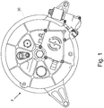
- the system 2 comprises a flywheel 4, a shaft 6, and bearing arrangements 8, 10 located around the shaft on either side of the flywheel 4, i.e. the first bearing arrangement 8 is located on one axial side of the flywheel, and the second bearing arrangement 10 is located on the other side of the flywheel 4 with respect to the axis of the shaft.
- Each of the bearing arrangements 8, 10 comprises bearings 12 mounted in a race 36 which is fixed rigidly to the shaft 6.
- An outer diameter of the bearing race 34 is held in a bearing collar 14.
- the bearing collar 14 is isolated from the flywheel housing 30 by an elastomeric component comprising a first pair of stiff elastomeric rings 16, 18 which are formed of a flurocarbon material.
- the rings 16, 18 are contained within annular channels 32, 34 formed within bearing collar 14. Thus the rings 16, 18 are located radially outwardly of the bearings 12 with respect to the shaft 6.
- the stiffness of the rings 16, 18 is sufficiently high such that in normal use of the system 2, the rings act to dampen any radial movement of the flywheel shaft 6, thus ensuring that the axis 'A' of the flywheel 4 does not move by more than a few microns. This ensures that a mechanical gear drive (not shown), which is connected to an end of the flywheel shaft 6, is maintained sufficiently close to its true centreline, thus ensuring correct operation of the gear drive and no contact between the periphery of the flywheel 4 and its housing 30.
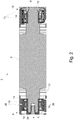
- One of the bearing arrangements, 8, is restrained in both radial and axial directions with respect to the shaft 6.
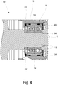
- Axial restraint is provided by a further elastomeric component comprising a second set of elastomeric rings, comprising a pair of elastomeric rings 20, 22 (as illustrated in the right hand side bearing arrangement 8 of Figure 2 , and in detail in Figure 4 ).
- the elastomeric components provide damping, thereby preventing NVH, and also preventing interaction of resonant modes of the flywheel and of the housing.
- An oil transmission passage is provided by a channel 24 in the housing, and channels 26, 28 in the bearing collar 14, to allow a controlled feed of oil (not shown) for lubrication of the bearings.
- the size of the oil transmission passage (i.e. the size of the channels 24, 26 and 28), is selected to provide a required damping coefficient of the assembly.
- the elastomeric rings 16, 18 are formed of a flurocarbon material, they may be formed of any suitable elastomer, including natural rubber.
- the elastomeric rings 16, 18 may alternatively be located radially inwardly of the bearings 12 with respect to the shaft 6, i.e. between the bearings 12 and the shaft 6.
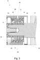
- the bearing arrangements are mounted to the shaft 6 via a metalastic bush which comprises two concentric steel collars 42, 44 which are separated by an elastomeric component comprising a moulded rubber collar 46.
- the metalastic bush 40 is located between the bearings arrangement 8', 10' and the shaft 6'.
- the bush 40 may alternatively be located between the bearings 12 and the flywheel housing 30.
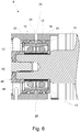
- a further alternative embodiment, as illustrated in Figure 6 may comprise a bearing arrangement 8" comprising a metalastic bush 40 in combination with a first set of elastomeric rings 16, 18, and/or the second set of elastomeric rings 20, 22, thereby providing a greater degree of radial and/or axial damping.
- the elastomeric rings 16, 18 are located between the bearings 12 and the housing 30, and the bush 40 is located between the bearings 12 and the shaft 6.
- the locations of the bush 40 and the elastomeric rings 16, 18 may be reversed.
- restraint of the bearing collar 14 is provided by a second pair of elastomeric rings 20, 22.
- the bearing collar 14 may be produced by moulding an elastomeric element and metal inner and outer rings as a single finished part. This alternative embodiment would be more suitable for mass production.
- first and/or second set of elastomeric rings may comprise a different number of rings.
Landscapes
- Engineering & Computer Science (AREA)
- General Engineering & Computer Science (AREA)
- Mechanical Engineering (AREA)
- Physics & Mathematics (AREA)
- Acoustics & Sound (AREA)
- Aviation & Aerospace Engineering (AREA)
- Support Of The Bearing (AREA)
- Mounting Of Bearings Or Others (AREA)
- Rolling Contact Bearings (AREA)
Claims (15)
- Hochgeschwindigkeitsschwungradsystem (2), umfassend:ein Schwungrad (4), das an einer Welle (6) montiert ist;ein Gehäuse, wobei die Welle (6) an dem Gehäuse montiert ist;eine erste primäre Lageranordnung (8) zwischen der Welle (6) und dem Gehäuse auf einer ersten Seite des Schwungrads (4); undeine zweite primäre Lageranordnung (10) zwischen der Welle (6) und dem Gehäuse auf einer zweiten Seite des Schwungrads (4);dadurch gekennzeichnet, dassdie erste und die zweite primäre Lageranordnung (8, 10) jeweils eine zugeordnete erste Elastomerkomponente aufweisen, die angeordnet ist, um radiale Rückhaltung bereitzustellen, und nur die erste primäre Lageranordnung (8) eine zugehörige zweite Elastomerkomponente aufweist, die angeordnet ist, um axiale Rückhaltung bereitzustellen,das System (2) ferner einen Ölübertragungsdurchlass (24, 26, 28) umfasst, der einen Kanal in dem Gehäuse umfasst, wodurch Öl über den Ölübertragungsdurchlass den Lagern zugeführt werden kann.
- Hochgeschwindigkeitsschwungradsystem (2) nach Anspruch 1, wobei jede primäre Lageranordnung (8, 10) Lager (12) umfasst, die in einem Laufring montiert sind.
- Hochgeschwindigkeitsschwungradsystem (2) nach Anspruch 2, wobei jeder Laufring (14) an der Welle (6) befestigt ist.
- Hochgeschwindigkeitsschwungradsystem (2) nach einem vorhergehenden Anspruch, wobei zumindest eine der ersten Elastomerkomponenten einen Ring umfasst.
- Hochgeschwindigkeitsschwungradsystem (2) nach Anspruch 4, wobei sich der Ring radial außerhalb der entsprechenden primären Lageranordnung zwischen der entsprechenden primären Lageranordnung und dem Gehäuse befindet.
- Hochgeschwindigkeitsschwungradsystem (2) nach Anspruch 4, wobei sich der Ring radial einwärts der entsprechenden primären Lageranordnung zwischen der entsprechenden primären Lageranordnung und der Welle (6) befindet.
- Hochgeschwindigkeitsschwungradsystem (2) nach Anspruch 4 oder Anspruch 5, wobei das System (2) ferner einen Lagerkragen (14) umfasst und wobei der Ring innerhalb ringförmiger Kanäle (32, 34) enthalten ist, die in dem Lagerkragen (14) bereitgestellt sind.
- Hochgeschwindigkeitsschwungradsystem (2) nach einem vorhergehenden Anspruch, ferner umfassend eine Buchse (40), die zwei konzentrische Metallkragen (42, 44) umfasst, wobei eine der ersten Elastomerkomponenten einen Gummikragen (46) umfasst, der sich zwischen den Metallkragen (42, 44) befindet.
- Hochgeschwindigkeitsschwungradsystem (2) nach Anspruch 8, wobei sich die Buchse (40) radial außerhalb der entsprechenden primären Lageranordnung zwischen der entsprechenden primären Lageranordnung und dem Gehäuse befindet.
- Hochgeschwindigkeitsschwungradsystem (2) nach Anspruch 8, wobei sich die Buchse (40) radial einwärts der entsprechenden primären Lageranordnung zwischen der entsprechenden primären Lageranordnung und der Welle (6) befindet.
- Hochgeschwindigkeitsschwungradsystem (2) nach Anspruch 5 und Anspruch 10.
- Hochgeschwindigkeitsschwungradsystem (2) nach Anspruch 6 und Anspruch 9.
- Hochgeschwindigkeitsschwungradsystem (2) nach einem der vorhergehenden Ansprüche, wobei die erste Elastomerkomponente und die zweite Elastomerkomponente separate Komponenten sind.
- Hochgeschwindigkeitsschwungradsystem (2) nach einem der vorhergehenden Ansprüche, wobei die zweite Elastomerkomponente einen Ring umfasst.
- Hochgeschwindigkeitsschwungradsystem (2) nach einem der vorhergehenden Ansprüche, wobei eine oder mehrere der Elastomerkomponenten aus einem Fluorkohlenstoffmaterial oder Naturkautschuk gebildet sind.
Applications Claiming Priority (2)
| Application Number | Priority Date | Filing Date | Title |
|---|---|---|---|
| GB1104406.2A GB2489021B (en) | 2011-03-16 | 2011-03-16 | High speed flywheel |
| PCT/GB2012/050448 WO2012123710A1 (en) | 2011-03-16 | 2012-02-28 | High speed flywheel |
Publications (2)
| Publication Number | Publication Date |
|---|---|
| EP2686577A1 EP2686577A1 (de) | 2014-01-22 |
| EP2686577B1 true EP2686577B1 (de) | 2021-05-19 |
Family
ID=43981049
Family Applications (1)
| Application Number | Title | Priority Date | Filing Date |
|---|---|---|---|
| EP12709686.5A Active EP2686577B1 (de) | 2011-03-16 | 2012-02-28 | Schwungrad mit hoher geschwindigkeit |
Country Status (7)
| Country | Link |
|---|---|
| US (1) | US9360082B2 (de) |
| EP (1) | EP2686577B1 (de) |
| JP (1) | JP6030076B2 (de) |
| KR (1) | KR20140045336A (de) |
| CN (1) | CN103443503B (de) |
| GB (1) | GB2489021B (de) |
| WO (1) | WO2012123710A1 (de) |
Families Citing this family (18)
| Publication number | Priority date | Publication date | Assignee | Title |
|---|---|---|---|---|
| GB2448930B (en) * | 2007-05-04 | 2009-08-19 | Flybrid Systems Llp | High speed flywheel seal |
| US20130199314A1 (en) * | 2012-01-26 | 2013-08-08 | Roller Bearing Company Of America, Inc. | Flywheel assembly for gyroscopic applications having ball bearing slug separators |
| JP2016508938A (ja) | 2012-11-20 | 2016-03-24 | ウォルダーソン・マイアミ・エルエルシー | エンジンブレーキ機構を備える4ストロークディーゼルエンジンによって駆動される車両から回収される運動および/またはポテンシャルエネルギから、水素を含む気体燃料を生成するための方法、およびそのような方法の実行に有用なシステム |
| JP6064783B2 (ja) * | 2013-05-23 | 2017-01-25 | 日本精工株式会社 | 転がり軸受 |
| FR3011880B1 (fr) * | 2013-10-10 | 2015-10-23 | Snecma | Dispositif de transfert d'huile entre deux referentiels en rotation l'un par rapport a l'autre, et turbomachine a helices pour aeronef avec un tel dispositif |
| US9303689B2 (en) | 2014-04-29 | 2016-04-05 | Roller Bearing Company Of America, Inc. | Non-rhythmically spaced rolling elements for reduction in bearing non-repeatable run-out |
| GB2535182B (en) * | 2015-02-11 | 2019-09-04 | Punch Flybrid Ltd | Carrier |
| GB2535201B (en) * | 2015-02-12 | 2019-10-30 | Punch Flybrid Ltd | Link member for a flywheel |
| CN107532652B (zh) * | 2015-06-04 | 2019-06-28 | 三菱重工发动机和增压器株式会社 | 轴承装置及增压器 |
| CN106763292B (zh) * | 2016-12-31 | 2018-09-25 | 玉环现代汽车配件厂 | 一种电磁离合器 |
| CN106870574B (zh) * | 2017-03-31 | 2019-04-30 | 安徽江淮纳威司达柴油发动机有限公司 | 一种导向轴承安装座 |
| GB2563617B (en) * | 2017-06-20 | 2020-04-08 | Dyson Technology Ltd | An electric machine |
| US10280974B2 (en) * | 2017-07-27 | 2019-05-07 | GM Global Technology Operations LLC | Structures and methods for controlled thermal expansion |
| JP7146353B2 (ja) * | 2018-12-25 | 2022-10-04 | 東芝三菱電機産業システム株式会社 | 軸受装置 |
| US10982730B2 (en) | 2019-03-04 | 2021-04-20 | Saint- Augustin Canada Electric Inc. | Flywheel systems and related methods |
| DE102019119224A1 (de) * | 2019-07-16 | 2021-01-21 | Dr. Ing. H.C. F. Porsche Aktiengesellschaft | Lagerdeckel |
| ES2985181T3 (es) * | 2019-09-10 | 2024-11-04 | Rockwool As | Rotor |
| CN113483014B (zh) * | 2021-06-23 | 2022-08-26 | 巴州大朴石油技术服务有限公司 | 一种用于井下作业的仪器滑车 |
Family Cites Families (29)
| Publication number | Priority date | Publication date | Assignee | Title |
|---|---|---|---|---|
| US2414335A (en) * | 1945-01-19 | 1947-01-14 | Jack & Heintz Prec Ind Inc | Ball-bearing assembly |
| US2439267A (en) * | 1945-02-23 | 1948-04-06 | Julius E Shafer | Resiliently mounted bearing |
| US2992868A (en) * | 1958-05-07 | 1961-07-18 | Vacha Fred | Mounting sleeve |
| JPS56153141A (en) * | 1980-04-26 | 1981-11-27 | Mitsubishi Electric Corp | Fly wheel device |
| JPS5720573A (en) * | 1980-07-10 | 1982-02-03 | Mitsubishi Electric Corp | Flywheel-type electric energy storage device |
| US4329000A (en) * | 1980-08-28 | 1982-05-11 | Caterpillar Tractor Co. | Self-contained, damped ball bearing assembly |
| JPS5837313A (ja) * | 1981-08-28 | 1983-03-04 | Mitsubishi Heavy Ind Ltd | 竪形高速回転体の軸受支持機構 |
| JPS60141141A (ja) * | 1983-12-28 | 1985-07-26 | Mitsubishi Electric Corp | フライホイ−ル電源装置 |
| US5253985A (en) * | 1990-07-04 | 1993-10-19 | Mtu Motoren- Und Turbinen-Union Friedrichshafen Gmbh | Exhaust gas turbocharger having rotor runners disposed in roller bearings |
| SE9503808L (sv) * | 1995-10-30 | 1996-10-28 | Skf Ab | Vagnskoppelenhet |
| JP2000130502A (ja) * | 1998-10-23 | 2000-05-12 | Chubu Electric Power Co Inc | 超電導フライホイール装置 |
| US6630761B1 (en) * | 2000-08-10 | 2003-10-07 | Christopher W. Gabrys | Combination mechanical and magnetic support for a flywheel power supply |
| JP3536022B2 (ja) * | 2000-10-04 | 2004-06-07 | ミネベア株式会社 | ピボット軸受装置 |
| WO2002061296A1 (de) | 2001-02-01 | 2002-08-08 | Luk Lamellen Und Kupplungsbau Beteiligungs Kg | Lageranordnung |
| FR2839396A1 (fr) * | 2002-05-06 | 2003-11-07 | Technofan | Moteur electrique a supports d'arbre ameliores |
| JP4442421B2 (ja) * | 2002-12-09 | 2010-03-31 | 日本精工株式会社 | 電動パワーステアリング装置 |
| US7240583B2 (en) * | 2003-10-28 | 2007-07-10 | Honeywell International, Inc. | Dual function, highly damped, structurally and thermally compliant auxiliary bearing assembly |
| JP2006038209A (ja) * | 2004-06-23 | 2006-02-09 | Mitsubishi Precision Co Ltd | フライホイール、コントロールモーメントジャイロおよびスライドダンピング機構 |
| JP2006242292A (ja) * | 2005-03-03 | 2006-09-14 | Nsk Ltd | 軸受装置 |
| JP2007100901A (ja) * | 2005-10-06 | 2007-04-19 | Mitsubishi Precision Co Ltd | フライホイール、コントロールモーメントジャイロおよびダンピング機構 |
| JP5010482B2 (ja) * | 2005-12-27 | 2012-08-29 | 三菱重工業株式会社 | 遊星ローラ式減速機 |
| JP2008202782A (ja) * | 2007-01-26 | 2008-09-04 | Jtekt Corp | 転がり軸受装置 |
| JP2008213074A (ja) * | 2007-03-02 | 2008-09-18 | Disco Abrasive Syst Ltd | 駆動機構及び切削装置 |
| DE102007037792A1 (de) * | 2007-08-10 | 2009-02-12 | Oerlikon Leybold Vacuum Gmbh | Pumpen-Lageranordnung |
| WO2010123764A2 (en) * | 2009-04-20 | 2010-10-28 | Borgwarner Inc. | Insulating and damping sleeve for a rolling element bearing cartridge |
| CN201434045Y (zh) * | 2009-05-12 | 2010-03-31 | 青岛海之冠汽车配件制造有限公司 | 减震式汽车飞轮 |
| EP2486295B1 (de) * | 2009-10-09 | 2018-03-14 | Dresser-Rand Company | Hilfslagersystem mit ölring für magnetgelagertes rotorsystem |
| CA2686843A1 (en) * | 2009-12-02 | 2011-06-02 | Flywheel Energy Systems Inc. | Compliant bearing mount with a position restoring shear force absorber |
| CN103171615B (zh) * | 2011-12-26 | 2016-12-28 | 株式会社捷太格特 | 电动动力转向装置 |
-
2011
- 2011-03-16 GB GB1104406.2A patent/GB2489021B/en active Active
-
2012
- 2012-02-28 JP JP2013558498A patent/JP6030076B2/ja active Active
- 2012-02-28 US US14/001,009 patent/US9360082B2/en active Active
- 2012-02-28 EP EP12709686.5A patent/EP2686577B1/de active Active
- 2012-02-28 KR KR1020137023480A patent/KR20140045336A/ko not_active Ceased
- 2012-02-28 CN CN201280013614.2A patent/CN103443503B/zh not_active Expired - Fee Related
- 2012-02-28 WO PCT/GB2012/050448 patent/WO2012123710A1/en not_active Ceased
Non-Patent Citations (1)
| Title |
|---|
| None * |
Also Published As
| Publication number | Publication date |
|---|---|
| GB201104406D0 (en) | 2011-04-27 |
| US9360082B2 (en) | 2016-06-07 |
| JP2014510885A (ja) | 2014-05-01 |
| GB2489021A (en) | 2012-09-19 |
| JP6030076B2 (ja) | 2016-11-24 |
| WO2012123710A1 (en) | 2012-09-20 |
| US20140033859A1 (en) | 2014-02-06 |
| CN103443503A (zh) | 2013-12-11 |
| CN103443503B (zh) | 2016-03-02 |
| EP2686577A1 (de) | 2014-01-22 |
| KR20140045336A (ko) | 2014-04-16 |
| GB2489021B (en) | 2013-08-14 |
Similar Documents
| Publication | Publication Date | Title |
|---|---|---|
| EP2686577B1 (de) | Schwungrad mit hoher geschwindigkeit | |
| US8956048B2 (en) | Squeeze film damper | |
| US8636413B2 (en) | Rotary bearing arrangement | |
| WO2016194198A1 (ja) | 軸受装置、及び、過給器 | |
| JP2019203506A (ja) | 一体型スクィーズフィルムダンパを備えた単列玉軸受 | |
| KR20110101235A (ko) | 자동차용에 특히 적합한 이중 감쇠 수단을 구비한 이중 감쇠 플라이휠 | |
| US11378123B2 (en) | Axial damper and displacement limit for turbomachine with rolling element bearings | |
| CN107532645A (zh) | 飞轮托架 | |
| CA2864041A1 (en) | Roller bearing set and corresponding rotating machine | |
| US20230375037A1 (en) | Moving element damper | |
| US20150010387A1 (en) | Exhaust gas turbocharger | |
| US5816712A (en) | Elastomeric cartridges for attenuation of bearing-generated vibration in electric motors | |
| US9341215B2 (en) | Bearing cage with a peripheral vibration damping ring | |
| CN102927196B (zh) | 一种与推进轴系同步运转的挤压油膜阻尼器 | |
| JP2017127150A (ja) | モータにおけるステータの固定構造 | |
| JP2014095419A (ja) | ダンパ付プーリ | |
| JP2011515639A (ja) | クランクシャフト用騒音遮断転動体軸受 | |
| CN105235505A (zh) | 一种降低车辆传动轴震动的安装结构 | |
| US9359899B2 (en) | Drive shaft system | |
| KR102939782B1 (ko) | 피니언 베어링 | |
| CN105626672A (zh) | 一种曲轴 | |
| JP2013022675A (ja) | 主軸装置 | |
| US20210341034A1 (en) | Damper Arrangement and Transmission for a Motor Vehicle Drive Train | |
| JP2007228689A (ja) | 車両用交流発電機の駆動方法 | |
| WO2007002903A1 (en) | Vibration damping device for bearings and method of dampening vibrations |
Legal Events
| Date | Code | Title | Description |
|---|---|---|---|
| PUAI | Public reference made under article 153(3) epc to a published international application that has entered the european phase |
Free format text: ORIGINAL CODE: 0009012 |
|
| 17P | Request for examination filed |
Effective date: 20130822 |
|
| AK | Designated contracting states |
Kind code of ref document: A1 Designated state(s): AL AT BE BG CH CY CZ DE DK EE ES FI FR GB GR HR HU IE IS IT LI LT LU LV MC MK MT NL NO PL PT RO RS SE SI SK SM TR |
|
| DAX | Request for extension of the european patent (deleted) | ||
| STAA | Information on the status of an ep patent application or granted ep patent |
Free format text: STATUS: EXAMINATION IS IN PROGRESS |
|
| 17Q | First examination report despatched |
Effective date: 20161201 |
|
| 19U | Interruption of proceedings before grant |
Effective date: 20171212 |
|
| 19W | Proceedings resumed before grant after interruption of proceedings |
Effective date: 20190301 |
|
| RAP1 | Party data changed (applicant data changed or rights of an application transferred) |
Owner name: PUNCH FLYBRID LIMITED |
|
| GRAP | Despatch of communication of intention to grant a patent |
Free format text: ORIGINAL CODE: EPIDOSNIGR1 |
|
| STAA | Information on the status of an ep patent application or granted ep patent |
Free format text: STATUS: GRANT OF PATENT IS INTENDED |
|
| INTG | Intention to grant announced |
Effective date: 20201222 |
|
| GRAS | Grant fee paid |
Free format text: ORIGINAL CODE: EPIDOSNIGR3 |
|
| GRAA | (expected) grant |
Free format text: ORIGINAL CODE: 0009210 |
|
| STAA | Information on the status of an ep patent application or granted ep patent |
Free format text: STATUS: THE PATENT HAS BEEN GRANTED |
|
| AK | Designated contracting states |
Kind code of ref document: B1 Designated state(s): AL AT BE BG CH CY CZ DE DK EE ES FI FR GB GR HR HU IE IS IT LI LT LU LV MC MK MT NL NO PL PT RO RS SE SI SK SM TR |
|
| REG | Reference to a national code |
Ref country code: GB Ref legal event code: FG4D |
|
| REG | Reference to a national code |
Ref country code: CH Ref legal event code: EP |
|
| REG | Reference to a national code |
Ref country code: DE Ref legal event code: R096 Ref document number: 602012075598 Country of ref document: DE |
|
| REG | Reference to a national code |
Ref country code: AT Ref legal event code: REF Ref document number: 1394270 Country of ref document: AT Kind code of ref document: T Effective date: 20210615 |
|
| REG | Reference to a national code |
Ref country code: IE Ref legal event code: FG4D |
|
| REG | Reference to a national code |
Ref country code: LT Ref legal event code: MG9D |
|
| REG | Reference to a national code |
Ref country code: AT Ref legal event code: MK05 Ref document number: 1394270 Country of ref document: AT Kind code of ref document: T Effective date: 20210519 |
|
| REG | Reference to a national code |
Ref country code: NL Ref legal event code: MP Effective date: 20210519 |
|
| PG25 | Lapsed in a contracting state [announced via postgrant information from national office to epo] |
Ref country code: AT Free format text: LAPSE BECAUSE OF FAILURE TO SUBMIT A TRANSLATION OF THE DESCRIPTION OR TO PAY THE FEE WITHIN THE PRESCRIBED TIME-LIMIT Effective date: 20210519 Ref country code: BG Free format text: LAPSE BECAUSE OF FAILURE TO SUBMIT A TRANSLATION OF THE DESCRIPTION OR TO PAY THE FEE WITHIN THE PRESCRIBED TIME-LIMIT Effective date: 20210819 Ref country code: HR Free format text: LAPSE BECAUSE OF FAILURE TO SUBMIT A TRANSLATION OF THE DESCRIPTION OR TO PAY THE FEE WITHIN THE PRESCRIBED TIME-LIMIT Effective date: 20210519 Ref country code: FI Free format text: LAPSE BECAUSE OF FAILURE TO SUBMIT A TRANSLATION OF THE DESCRIPTION OR TO PAY THE FEE WITHIN THE PRESCRIBED TIME-LIMIT Effective date: 20210519 Ref country code: LT Free format text: LAPSE BECAUSE OF FAILURE TO SUBMIT A TRANSLATION OF THE DESCRIPTION OR TO PAY THE FEE WITHIN THE PRESCRIBED TIME-LIMIT Effective date: 20210519 |
|
| PG25 | Lapsed in a contracting state [announced via postgrant information from national office to epo] |
Ref country code: LV Free format text: LAPSE BECAUSE OF FAILURE TO SUBMIT A TRANSLATION OF THE DESCRIPTION OR TO PAY THE FEE WITHIN THE PRESCRIBED TIME-LIMIT Effective date: 20210519 Ref country code: GR Free format text: LAPSE BECAUSE OF FAILURE TO SUBMIT A TRANSLATION OF THE DESCRIPTION OR TO PAY THE FEE WITHIN THE PRESCRIBED TIME-LIMIT Effective date: 20210820 Ref country code: IS Free format text: LAPSE BECAUSE OF FAILURE TO SUBMIT A TRANSLATION OF THE DESCRIPTION OR TO PAY THE FEE WITHIN THE PRESCRIBED TIME-LIMIT Effective date: 20210919 Ref country code: SE Free format text: LAPSE BECAUSE OF FAILURE TO SUBMIT A TRANSLATION OF THE DESCRIPTION OR TO PAY THE FEE WITHIN THE PRESCRIBED TIME-LIMIT Effective date: 20210519 Ref country code: RS Free format text: LAPSE BECAUSE OF FAILURE TO SUBMIT A TRANSLATION OF THE DESCRIPTION OR TO PAY THE FEE WITHIN THE PRESCRIBED TIME-LIMIT Effective date: 20210519 Ref country code: PL Free format text: LAPSE BECAUSE OF FAILURE TO SUBMIT A TRANSLATION OF THE DESCRIPTION OR TO PAY THE FEE WITHIN THE PRESCRIBED TIME-LIMIT Effective date: 20210519 Ref country code: PT Free format text: LAPSE BECAUSE OF FAILURE TO SUBMIT A TRANSLATION OF THE DESCRIPTION OR TO PAY THE FEE WITHIN THE PRESCRIBED TIME-LIMIT Effective date: 20210920 Ref country code: NO Free format text: LAPSE BECAUSE OF FAILURE TO SUBMIT A TRANSLATION OF THE DESCRIPTION OR TO PAY THE FEE WITHIN THE PRESCRIBED TIME-LIMIT Effective date: 20210819 Ref country code: ES Free format text: LAPSE BECAUSE OF FAILURE TO SUBMIT A TRANSLATION OF THE DESCRIPTION OR TO PAY THE FEE WITHIN THE PRESCRIBED TIME-LIMIT Effective date: 20210519 |
|
| PG25 | Lapsed in a contracting state [announced via postgrant information from national office to epo] |
Ref country code: NL Free format text: LAPSE BECAUSE OF FAILURE TO SUBMIT A TRANSLATION OF THE DESCRIPTION OR TO PAY THE FEE WITHIN THE PRESCRIBED TIME-LIMIT Effective date: 20210519 |
|
| PG25 | Lapsed in a contracting state [announced via postgrant information from national office to epo] |
Ref country code: DK Free format text: LAPSE BECAUSE OF FAILURE TO SUBMIT A TRANSLATION OF THE DESCRIPTION OR TO PAY THE FEE WITHIN THE PRESCRIBED TIME-LIMIT Effective date: 20210519 Ref country code: EE Free format text: LAPSE BECAUSE OF FAILURE TO SUBMIT A TRANSLATION OF THE DESCRIPTION OR TO PAY THE FEE WITHIN THE PRESCRIBED TIME-LIMIT Effective date: 20210519 Ref country code: CZ Free format text: LAPSE BECAUSE OF FAILURE TO SUBMIT A TRANSLATION OF THE DESCRIPTION OR TO PAY THE FEE WITHIN THE PRESCRIBED TIME-LIMIT Effective date: 20210519 Ref country code: SK Free format text: LAPSE BECAUSE OF FAILURE TO SUBMIT A TRANSLATION OF THE DESCRIPTION OR TO PAY THE FEE WITHIN THE PRESCRIBED TIME-LIMIT Effective date: 20210519 Ref country code: SM Free format text: LAPSE BECAUSE OF FAILURE TO SUBMIT A TRANSLATION OF THE DESCRIPTION OR TO PAY THE FEE WITHIN THE PRESCRIBED TIME-LIMIT Effective date: 20210519 Ref country code: RO Free format text: LAPSE BECAUSE OF FAILURE TO SUBMIT A TRANSLATION OF THE DESCRIPTION OR TO PAY THE FEE WITHIN THE PRESCRIBED TIME-LIMIT Effective date: 20210519 |
|
| REG | Reference to a national code |
Ref country code: DE Ref legal event code: R097 Ref document number: 602012075598 Country of ref document: DE |
|
| PLBE | No opposition filed within time limit |
Free format text: ORIGINAL CODE: 0009261 |
|
| STAA | Information on the status of an ep patent application or granted ep patent |
Free format text: STATUS: NO OPPOSITION FILED WITHIN TIME LIMIT |
|
| 26N | No opposition filed |
Effective date: 20220222 |
|
| PG25 | Lapsed in a contracting state [announced via postgrant information from national office to epo] |
Ref country code: IS Free format text: LAPSE BECAUSE OF FAILURE TO SUBMIT A TRANSLATION OF THE DESCRIPTION OR TO PAY THE FEE WITHIN THE PRESCRIBED TIME-LIMIT Effective date: 20210919 Ref country code: AL Free format text: LAPSE BECAUSE OF FAILURE TO SUBMIT A TRANSLATION OF THE DESCRIPTION OR TO PAY THE FEE WITHIN THE PRESCRIBED TIME-LIMIT Effective date: 20210519 |
|
| PG25 | Lapsed in a contracting state [announced via postgrant information from national office to epo] |
Ref country code: MC Free format text: LAPSE BECAUSE OF FAILURE TO SUBMIT A TRANSLATION OF THE DESCRIPTION OR TO PAY THE FEE WITHIN THE PRESCRIBED TIME-LIMIT Effective date: 20210519 |
|
| REG | Reference to a national code |
Ref country code: CH Ref legal event code: PL |
|
| REG | Reference to a national code |
Ref country code: BE Ref legal event code: MM Effective date: 20220228 |
|
| PG25 | Lapsed in a contracting state [announced via postgrant information from national office to epo] |
Ref country code: LU Free format text: LAPSE BECAUSE OF NON-PAYMENT OF DUE FEES Effective date: 20220228 |
|
| PG25 | Lapsed in a contracting state [announced via postgrant information from national office to epo] |
Ref country code: LI Free format text: LAPSE BECAUSE OF NON-PAYMENT OF DUE FEES Effective date: 20220228 Ref country code: IE Free format text: LAPSE BECAUSE OF NON-PAYMENT OF DUE FEES Effective date: 20220228 Ref country code: CH Free format text: LAPSE BECAUSE OF NON-PAYMENT OF DUE FEES Effective date: 20220228 |
|
| PG25 | Lapsed in a contracting state [announced via postgrant information from national office to epo] |
Ref country code: BE Free format text: LAPSE BECAUSE OF NON-PAYMENT OF DUE FEES Effective date: 20220228 |
|
| PG25 | Lapsed in a contracting state [announced via postgrant information from national office to epo] |
Ref country code: HU Free format text: LAPSE BECAUSE OF FAILURE TO SUBMIT A TRANSLATION OF THE DESCRIPTION OR TO PAY THE FEE WITHIN THE PRESCRIBED TIME-LIMIT; INVALID AB INITIO Effective date: 20120228 |
|
| PG25 | Lapsed in a contracting state [announced via postgrant information from national office to epo] |
Ref country code: MK Free format text: LAPSE BECAUSE OF FAILURE TO SUBMIT A TRANSLATION OF THE DESCRIPTION OR TO PAY THE FEE WITHIN THE PRESCRIBED TIME-LIMIT Effective date: 20210519 Ref country code: CY Free format text: LAPSE BECAUSE OF FAILURE TO SUBMIT A TRANSLATION OF THE DESCRIPTION OR TO PAY THE FEE WITHIN THE PRESCRIBED TIME-LIMIT Effective date: 20210519 |
|
| PG25 | Lapsed in a contracting state [announced via postgrant information from national office to epo] |
Ref country code: TR Free format text: LAPSE BECAUSE OF FAILURE TO SUBMIT A TRANSLATION OF THE DESCRIPTION OR TO PAY THE FEE WITHIN THE PRESCRIBED TIME-LIMIT Effective date: 20210519 |
|
| PG25 | Lapsed in a contracting state [announced via postgrant information from national office to epo] |
Ref country code: MT Free format text: LAPSE BECAUSE OF FAILURE TO SUBMIT A TRANSLATION OF THE DESCRIPTION OR TO PAY THE FEE WITHIN THE PRESCRIBED TIME-LIMIT Effective date: 20210519 |
|
| PGFP | Annual fee paid to national office [announced via postgrant information from national office to epo] |
Ref country code: GB Payment date: 20260218 Year of fee payment: 15 |
|
| PGFP | Annual fee paid to national office [announced via postgrant information from national office to epo] |
Ref country code: DE Payment date: 20260316 Year of fee payment: 15 |
|
| PGFP | Annual fee paid to national office [announced via postgrant information from national office to epo] |
Ref country code: IT Payment date: 20260223 Year of fee payment: 15 |
|
| PGFP | Annual fee paid to national office [announced via postgrant information from national office to epo] |
Ref country code: FR Payment date: 20260227 Year of fee payment: 15 |