EP2686713B1 - Profondeur maximale d'investigation de mesures dans une formation - Google Patents
Profondeur maximale d'investigation de mesures dans une formation Download PDFInfo
- Publication number
- EP2686713B1 EP2686713B1 EP12757334.3A EP12757334A EP2686713B1 EP 2686713 B1 EP2686713 B1 EP 2686713B1 EP 12757334 A EP12757334 A EP 12757334A EP 2686713 B1 EP2686713 B1 EP 2686713B1
- Authority
- EP
- European Patent Office
- Prior art keywords
- investigation
- logging tool
- resistivity
- electromagnetic
- depth
- Prior art date
- Legal status (The legal status is an assumption and is not a legal conclusion. Google has not performed a legal analysis and makes no representation as to the accuracy of the status listed.)
- Active
Links
Images


Classifications
-
- G—PHYSICS
- G01—MEASURING; TESTING
- G01V—GEOPHYSICS; GRAVITATIONAL MEASUREMENTS; DETECTING MASSES OR OBJECTS; TAGS
- G01V3/00—Electric or magnetic prospecting or detecting; Measuring magnetic field characteristics of the earth, e.g. declination, deviation
- G01V3/18—Electric or magnetic prospecting or detecting; Measuring magnetic field characteristics of the earth, e.g. declination, deviation specially adapted for well-logging
Definitions
- the present disclosure relates generally to the logging of subsurface formations surrounding a wellbore using a downhole logging tool, and particularly to determining the maximum depth of investigation of measurements made in the formations.
- Logging tools have long been used in wellbores to make, for example, formation evaluation measurements to infer properties of the formations surrounding the borehole and the fluids in the formations.
- Common logging tools include electromagnetic tools, nuclear tools, and nuclear magnetic resonance (NMR) tools, though various other tool types are also used.
- NMR nuclear magnetic resonance
- MWD measurement-while-drilling
- LWD logging-while-drilling
- MWD tools typically provide drilling parameter information such as weight on the bit, torque, temperature, pressure, direction, and inclination.
- LWD tools typically provide formation evaluation measurements such as resistivity, porosity, and NMR distributions.
- MWD and LWD tools often have components common to wireline tools (e.g., transmitting and receiving antennas), but MWD and LWD tools must be constructed to not only endure but to operate in the harsh environment of drilling.
- Prior art tools and methods have focused on determining and displaying (mapping) the distance between a measurement sensor carried on the tool and a bed boundary. Identification of a bed boundary is typically characterized by a change in one or more petrophysical properties of the formation. Various techniques and workflows exist to evaluate the distance to the boundary, but none of those allow one to determine the formation volume investigated by deep and azimuthal measurements in the absence of a recognizable bed boundary, or in the case of a measurement that reads beyond a relatively near bed boundary deep into an adjacent formation layer.
- US 2004/046561 describes a method for performing resistivity measurements for the purpose of geo-steering with 180-degree azimuth resolution. All the measurements represent a complementary set of data acquired in two operational modes.
- the directional mode providing sensitivity of the received signals to the azimuth characteristics of the formation.
- the deep mode provides a large depth of investigation for resistivity determination and bed boundary detection.
- the directional mode can be implemented using one receiving coil placed in between quadruple type transmitter.
- the deep mode represents either array induction measurements or multiple propagation resistivity measurements that provide high depth of investigation for resistivity determination and bed boundary detection.
- WO 2009/073277 describes a method comprising processing of raw logging or image data provided by a tool to estimate formation attributes or features (e.g., density and dip angle). The estimations may be iteratively refined using effective volume of interest (EVOI) information. Depth boundaries of formation information provided by the tool are shifted as a function of azimuth for correct spatial positioning of formation features using EVOI information.
- EVOI
- the present disclosure relates to a system as defined in claims 1 to 5 and in a method for determining a maximum depth of investigation as defined in claims 6 to 15
- Figure 1 illustrates a well site system in which various embodiments can be employed.
- the well site can be onshore or offshore.
- a borehole 11 is formed in subsurface formations by rotary drilling in a manner that is well known.
- Some embodiments can also use directional drilling, as will be described hereinafter.
- a drill string 12 is suspended within the borehole 11 and has a bottom hole assembly 100 which includes a drill bit 105 at its lower end.
- the surface system includes platform and derrick assembly 10 positioned over the borehole 11, the assembly 10 including a rotary table 16, kelly 17, hook 18 and rotary swivel 19.
- the drill string 12 is rotated by the rotary table 16, energized by means not shown, which engages the kelly 17 at the upper end of the drill string.
- the drill string 12 is suspended from a hook 18, attached to a traveling block (also not shown), through the kelly 17 and a rotary swivel 19 which permits rotation of the drill string relative to the hook.
- a top drive system could alternatively be used.
- the surface system further includes drilling fluid or mud 26 stored in a pit 27 formed at the well site.
- a pump 29 delivers the drilling fluid 26 to the interior of the drill string 12 via a port in the swivel 19, causing the drilling fluid to flow downwardly through the drill string 12 as indicated by the directional arrow 8.
- the drilling fluid exits the drill string 12 via ports in the drill bit 105, and then circulates upwardly through the annulus region between the outside of the drill string and the wall of the borehole, as indicated by the directional arrows 9.
- the drilling fluid lubricates the drill bit 105 and carries formation cuttings up to the surface as it is returned to the pit 27 for recirculation.
- the bottom hole assembly 100 of the illustrated embodiment includes a logging-while-drilling (LWD) module 120, a measuring-while-drilling (MWD) module 130, a roto-steerable system and motor, and drill bit 105.
- LWD logging-while-drilling
- MWD measuring-while-drilling
- roto-steerable system and motor drill bit 105.
- the LWD module 120 is housed in a special type of drill collar, as is known in the art, and can contain one or a plurality of known types of logging tools. It will also be understood that more than one LWD and/or MWD module can be employed, e.g. as represented at 120A. (References, throughout, to a module at the position of 120 can alternatively mean a module at the position of 120A as well.)
- the LWD module includes capabilities for measuring, processing, and storing information, as well as for communicating with the surface equipment. In the present embodiment, the LWD module includes a resistivity measuring device.
- the MWD module 130 is also housed in a special type of drill collar, as is known in the art, and can contain one or more devices for measuring characteristics of the drill string and drill bit.
- the MWD tool further includes an apparatus (not shown) for generating electrical power to the downhole system. This may typically include a mud turbine generator powered by the flow of the drilling fluid, it being understood that other power and/or battery systems may be employed.
- the MWD module includes one or more of the following types of measuring devices: a weight-on-bit measuring device, a torque measuring device, a vibration measuring device, a shock measuring device, a stick/slip measuring device, a direction measuring device, and an inclination measuring device.
- FIG. 2 An example of a tool which can be the LWD tool 120, or can be a part of an LWD tool suite 120A, is shown in Figure 2 .
- upper and lower transmitting antennas, T 1 and T 2 have upper and lower receiving antennas, R 1 and R 2 , therebetween.
- the antennas are formed in recesses in a modified drill collar and mounted in insulating material.
- the phase shift of electromagnetic energy as between the receivers provides an indication of formation resistivity at a relatively shallow depth of investigation, and the attenuation of electromagnetic energy as between the receivers provides an indication of formation resistivity at a relatively deep depth of investigation.
- U.S. Patent No. 4,899,112 can be referred to for further details.
- attenuation-representative signals and phase-representative signals are coupled to a processor, an output of which is coupleable to a telemetry circuit.
- Recent electromagnetic (EM) logging tools use one or more tilted or transverse antennas, with or without axial antennas.
- Those antennas may be transmitters or receivers.
- a tilted antenna is one whose dipole moment is neither parallel nor perpendicular to the longitudinal axis of the tool.
- a transverse antenna is one whose dipole moment is perpendicular to the longitudinal axis of the tool, and an axial antenna is one whose dipole moment is parallel to the longitudinal axis of the tool.
- a triaxial antenna is one in which three antennas (i.e., antenna coils) are arranged to be mutually orthogonal. Typically, one antenna (coil) is axial and the other two are transverse.
- Two antennas are said to have equal angles if their dipole moment vectors intersect the tool's longitudinal axis at the same angle.
- two tilted antennas have the same tilt angle if their dipole moment vectors, having their tails conceptually fixed to a point on the tool's longitudinal axis, lie on the surface of a right circular cone centered on the tool's longitudinal axis and having its vertex at that reference point.
- Transverse antennas obviously have equal angles of 90 degrees, and that is true regardless of their azimuthal orientations relative to the tool.
- Prior art logging tools/methods do not provide feedback or information to an operator to indicate the maximum depth of investigation of the tool when no boundary is detected.
- Most deep and azimuthally sensitive measurements have a depth of investigation that depends on the tool configuration, as well as the formation properties. As such, the depth of investigation (DOI), or volume of investigation (VOI) for azimuthally sensitive measurements, should not be considered constant.
- DOI depth of investigation
- VOI volume of investigation
- the maximum DOI of a deep, azimuthal EM measurement for which no formation boundaries are identified can be determined and displayed. This information may be used to optimize the use of this type of measurement and also other types of deep-reading measurements.
- Applications include well placement, formation properties evaluation, and reservoir structure evaluation, to name a few examples. Those applications may be performed in real-time or in recorded mode. For convenience and clarity, the disclosure herein discusses EM measurements, but other measurement types may be used. Parameters may also be the result of computations made using one or more sensor measurements, such as resistivity of the formation, distance to a resistivity contrast, fluid (water, oil, and gas) saturation, formation pressure, fracture pressure, and permeability.
- Data collected at various depths along a wellbore trajectory may be processed in real-time or it may be recorded and used in subsequent processing, or both.
- a specific data format is preferably used to allow data transfer through different 3-D representation platforms.
- the measurements themselves are typically measured versus time, but other domains may be used. Measurements are acquired, for example, with LWD and MWD tools, using downhole and surface sensors of pressure, temperature, fluid flow, and so forth. Because some parameters vary azimuthally around the circumference of the wellbore, certain logging sensors are designed to measure those azimuthally varying parameters. Those measurements allow for the detection and visualization of axial and azimuthal changes in formation and borehole conditions. Properties and contents of the formation matrix, formation fluids, borehole fluids, borehole cuttings and other constituent material, borehole size and shape, formation parameters, and fluid parameters may be investigated.
- the data can be analyzed to determine a volume of clearance.
- the volume of clearance may be a cylindrical volume centered on the tool axis.
- the cylindrical volume of clearance is shaped like a "pillbox", having a radius proportional to the transmitter-receiver distance, and a relatively short "height" compared to that radius.
- Measurements may be analyzed to investigate the effect of the formation on the measurements, and to evaluate the overall sensitivity (e.g., maximum signal/noise ratio) for which a signal still carries discernable formation property information.
- the analysis provides for the detection and visualization of axial, azimuthal, and radial changes in formation property geometry.
- a 3-D, spatially oriented volume of clearance positioned in a 3-D environment along the wellbore's trajectory, whether actual or proposed, may be displayed.
- Color-coding of one or more formation property boundaries may be produced in such a display.
- Multiple circles or ellipsoids of different size and shape, placed adjacently, may be generated to represent the change (or lack of change) in a volume of clearance.
- a 3-D display of the distance between the tool and the maximum distance of investigation may be produced.
- the vertical resistivity and horizontal resistivity of an anisotropic formation can be determined.
- Various frequencies and transmitter-receiver spacings are used to make the measurements, giving rise to various depths of investigation.
- the particular frequency and spacing combination that provides the deepest DOI, as a function of the determined resistivities, can be identified.
- the identified measurement coupling that provides the deepest DOI can be used to determine a noise threshold.
- the noise threshold is that level of noise for which the signal becomes unreliably difficult to ascertain and distinguish.
- the noise itself typically depends on the frequency and transmitter-receiver spacing and is characterized by the electronic noise of the tool.
- a resistivity ratio can be crafted that characterizes a desired or hypothesized resistivity contrast.
- the numerator of the ratio is the determined horizontal resistivity
- the denominator is a user-defined or selected resistivity.
- the resistivity ratio and the identified measurement coupling can be used to model the signal response as a function of distance of the tool from a hypothetical or presumed bed boundary.
- the signal strength can be plotted against the depth of investigation distance, as shown in Figure 3 .
- a noise threshold can be set at multiple positions or values, as desired by a user. For example, it may be set at two or three times the standard deviation of the noise. Other values may be chosen based on other criteria.
- the noise threshold can be plotted on the modeled signal strength plot as a horizontal line.
- the noise threshold line intersects the curve of the signal strength plot at a point referred to herein as the "cutoff' point. It is assumed the signal strength below the noise threshold is too low to be reliable, thus the maximum DOI for which there is a reasonable level of confidence in the signal is that corresponding to the cutoff point. That is, a vertical line dropped from the cutoff point intersects the horizontal axis at the maximum DOI of the tool for the given measurement environment.
- FIG. 4 shows a flowchart 400 in which the above steps are enumerated.
- step 402 data is obtained and, if the data is EM data, the resistivities are determined (step 404). For other measurement types, other physical properties are determined and used similarly.
- the particular measurement coupling that yields the deepest DOI, as a function of the determined resistivities, is identified (step 406).
- the identified measurement coupling is used to determine a noise threshold (step 408).
- a resistivity ratio is formed using determined and selected resistivity values (step 410).
- a model signal response is determined as a function of DOI using the identified measurement coupling and the resistivity ratio, and plotted (step 412).
- the determined noise threshold is plotted on the signal response plot and a cutoff point determined (step 414).
- the maximum DOI is then determined based on the determined cutoff point (step 416).
- DOI display One purpose of a DOI display is to graphically indicate to a user that even though no boundaries are detected by an inversion, based on the absence of signal, one can still conclude there are no boundaries within the distance indicated by the maximum DOI. Thus, a volume of clearance can be determined.
- a user can evaluate the maximum depth of investigation at each station based on selected inversion inputs. For example, the evaluation can be based on a resistivity profile or the results of other types of inversion.
- a resistivity profile may be predefined during pre-job work, or a user may input, for example, a conductive shoulder bed's resistivity, if known or estimated.
- a detection range can be determined based on the inverted models.
- the DOI will generate a zone that can be marked distinctly and differently from the actual resistivity contrast so that it is not confused with a physical boundary.
- three times the standard deviation of the noise of each measurement e.g., 0.025 dB of attenuation of the azimuthal measurement, 0.15 degrees of phase shift in the azimuthal measurement
- the DOI depends not only on the distance to the bed but also on the resistivity contrast or profile.
- the maximum DOI may be obtained from deep directional measurements taken from an input set of directional measurements.
- an input set of directional measurement includes 96 inch s (243,84 cm) spacing measurements and 34 inch (86.36 cm) spacing measurements
- the 96 inch (243,84 cm) spacing measurements are preferably used to determine the maximum DOI.
- the input set of directional measurement includes 34 inch (86.36 cm) spacing measurements and 22 inch (55.88 cm) spacing measurements
- the 34 inch (86.36 cm) directional measurements are preferably used to determine the maximum DOI.
- a maximum DOI for the tool can be determined.
- the maximum DOI can be determined by moving the boundary position away until one of the deep directional measurements (likely the 96 inch (243,84 cm)) falls below three times the measurement's standard deviation.
- the maximum DOI of the lower boundary can be obtained by fixing the upper boundary position, the tool position, the upper layer resistivity (Ru), the horizontal resistivity of the center layer (Rh), the vertical resistivity of the center layer (Rv), and the lower layer resistivity (Rl), and moving the lower boundary position away until the absolute signal difference between the deep directional measurements with and without the lower boundary is smaller than three times the measurement's standard deviation.
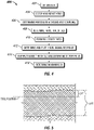
- a synthetic three-layer example demonstrates the process.
- the center bed thickness is eight feet and the tool position is two feet below the upper boundary, as shown in Figure 5 .
- the signal differences with and without the lower boundary are plotted in Figures 6A-6D as a function of the distance of the lower boundary to the tool position. From Figure 6A (SAD1), the maximum DOI is 7.9 feet (240.792 cm). In this case, the three times the measurement specification (0.25db) generates two values: 7.9 feet (240.792 cm) and 17.6 feet (536.448 cm). We select the shorter one.
- Similar logic can be used to determine the maximum DOI towards the upper boundary layer.
- the formation model is preferably simplified to a three-layer model first, and the method described above is used to get the maximum DOI range.
- a weighted average based on the formation conductivity and the distance to the tool measured from the center of the bed can be performed using the below equation.
- d iu is the distance from the upper layer boundary to the center of the i th upper layer
- C iu is the conductivity value of the i th upper layer
- d il is the distance from the lower layer boundary to the center of i th lower layer
- C iu is the conductivity value of the i th lower layer.
- the DOI defined in this case shares certain similarities with the signal-to-noise ratio alluded to above. Both indicate whether the measurement signals are good indicators of the existence of a boundary. However, the quantities are different.
- the signal-to-noise ratio provides a simple way to indicate whether the signal measured for a particular tool position is below the noise specification. However, any additional interpretation regarding the existence of a boundary far away is without merit.
- the DOI indicates how far away the boundary needs to be before the measurement become insensitive to it, thus giving confidence to interpretation when the inverted boundary is within the calculated detection range.
Landscapes
- Life Sciences & Earth Sciences (AREA)
- Engineering & Computer Science (AREA)
- Environmental & Geological Engineering (AREA)
- Geology (AREA)
- Remote Sensing (AREA)
- Physics & Mathematics (AREA)
- General Life Sciences & Earth Sciences (AREA)
- General Physics & Mathematics (AREA)
- Geophysics (AREA)
- Geophysics And Detection Of Objects (AREA)
- Investigation Of Foundation Soil And Reinforcement Of Foundation Soil By Compacting Or Drainage (AREA)
Claims (15)
- Système comprenant :un outil de diagraphie électromagnétique (120) présentant une pluralité de couplages de mesure émetteur-récepteur, dans lequel l'outil de diagraphie électromagnétique (120) est configuré pour être disposé à l'intérieur d'une formation souterraine d'un puits de forage (11) et configuré pour obtenir des mesures électromagnétiques correspondant à une mesure d'une propriété de formation souterraine du puits de forage (11), et dans lequel les mesures électromagnétiques se rapportent à une ou plusieurs caractéristiques de matériaux le long d'une trajectoire du puits de forage (11) à une pluralité de profondeurs ; etun processeur configuré pour :recevoir (402) les mesures électromagnétiques provenant de l'outil de diagraphie électromagnétique (120) disposé dans la formation souterraine ;déterminer (408) un seuil de bruit basé sur un couplage de mesure émetteur-récepteur sélectionné de l'outil de diagraphie électromagnétique (120) et le bruit électrique de l'outil de diagraphie électromagnétique (120) ;déterminer (410) un rapport de résistivité basé sur les mesures électromagnétiques reçues ; modéliser (412) une réponse de signal de l'outil de diagraphie électromagnétique (120) à l'aide du rapport de résistivité ;tracer (412, 414) une première courbe représentative de la réponse du signal en fonction de l'intensité du signal et de la distance de la profondeur d'investigation et une seconde courbe représentative du seuil de bruit ; etdéterminer (416) une profondeur maximale d'investigation dans la formation souterraine en tant que la distance de profondeur d'investigation correspondant à l'endroit où les première et seconde courbes se croisent sur le tracé.
- Système selon la revendication 1, dans lequel aucune couche limite n'est détectée.
- Système selon la revendication 1, dans lequel le processeur est apte à déterminer un volume de dégagement entourant un puits de forage dans lequel l'outil de diagraphie électromagnétique est disposé sur la base de la profondeur maximale d'investigation.
- Système selon la revendication 3 comprenant en outre l'affichage du volume de dégagement.
- Système selon la revendication 1, dans lequel le couplage de mesure émetteur-récepteur sélectionné est celui qui fournit la plus grande profondeur d'investigation pour l'outil de diagraphie électromagnétique par rapport à tous les autres couplages de mesure émetteur-récepteur de l'outil de diagraphie électromagnétique.
- Procédé servant à déterminer une profondeur maximale d'investigation comprenant :la disposition d'un outil de diagraphie électromagnétique (120) présentant une pluralité d'espacements émetteur-récepteur dans un trou de forage (11) formé dans une formation souterraine ;l'obtention (402) des mesures électromagnétiques provenant de l'outil de diagraphie électromagnétique (120) correspondant à une mesure d'une propriété de formation souterraine du trou de forage (11), dans lequel les mesures électromagnétiques se rapportent à une ou plusieurs caractéristiques de matériaux le long d'une trajectoire du trou de forage (11) à une pluralité de profondeurs ;à l'aide d'un processeur pour :déterminer (408) un seuil de bruit basé au moins partiellement sur un espacement émetteur-récepteur sélectionné de l'outil de diagraphie électromagnétique (120) et le bruit électrique caractéristique de l'outil de diagraphie électromagnétique (120) ;déterminer un rapport de résistivité (410) basé sur les mesures électromagnétiques obtenues ; modéliser (412) une réponse de signal de l'outil de diagraphie électromagnétique (120) à l'aide du rapport de résistivité ;tracer (412) une première courbe représentative de la réponse du signal en fonction de l'intensité du signal et de la distance de la profondeur d'investigationtracer (414) une seconde courbe représentative du seuil de bruit sur le même tracé que la première courbe ; etdéterminer (416) une profondeur maximale d'investigation dans la formation souterraine en tant que la distance de profondeur d'investigation correspondant à l'endroit où les première et seconde courbes se croisent sur le tracé.
- Procédé selon la revendication 6, dans lequel les mesures électromagnétiques comprennent une résistivité horizontale et une résistivité verticale.
- Procédé selon la revendication 7, dans lequel le rapport de résistivité est déterminé comme un rapport entre la résistivité horizontale et une résistivité définie par l'utilisateur qui donne un contraste de résistivité souhaité.
- Procédé selon la revendication 6, dans lequel l'espacement émetteur-récepteur sélectionné est celui qui fournit la plus grande profondeur d'investigation pour l'outil de diagraphie électromagnétique par rapport à tous les autres espacements émetteur-récepteur de l'outil de diagraphie électromagnétique.
- Procédé selon la revendication 6, dans lequel la profondeur maximale d'investigation est utilisée pour déterminer un volume de dégagement centré sur l'axe de l'outil de diagraphie électromagnétique.
- Procédé selon la revendication 6, dans lequel lorsque la première courbe et la seconde courbe se coupent en plus d'un point, le point correspondant à une distance de profondeur d'investigation moindre est sélectionné comme profondeur d'investigation maximale.
- Procédé de la revendication 6, comprenant en outre la détermination du volume de dégagement entourant le puits de forage à l'aide de la profondeur d'investigation radiale maximale déterminée.
- Procédé selon la revendication 12 comprenant en outre l'affichage du volume de dégagement.
- Procédé selon la revendication 13, dans lequel l'affichage comprend l'un parmi le codage couleur d'une ou plusieurs limites de propriétés de la formation, le placement adjacent de plusieurs cercles ou ellipsoïdes de taille et de forme différentes ou le traçage d'un volume de dégagement orienté spatialement en 3D positionné dans un environnement en 3D le long de la trajectoire d'un puits de forage.
- Procédé selon la revendication 6, dans lequel la propriété de la formation souterraine comprend au moins un élément parmi une tension, une résistivité globale, une résistivité horizontale, une résistivité verticale, une porosité, une perméabilité, une saturation de fluide, un temps de relaxation de RMN, un champ magnétique, une réponse sonique, une taille de trou de forage, une forme de trou de forage, une composition de fluide de trou de forage, un paramètre de mesure en cours de forage (MWD) et un paramètre de diagraphie en cours de forage (LWD).
Applications Claiming Priority (2)
| Application Number | Priority Date | Filing Date | Title |
|---|---|---|---|
| US13/048,833 US9043153B2 (en) | 2011-03-15 | 2011-03-15 | Maximum depth of investigation of measurements in a formation |
| PCT/US2012/028067 WO2012125369A2 (fr) | 2011-03-15 | 2012-03-07 | Profondeur maximale d'investigation de mesures dans une formation |
Publications (4)
| Publication Number | Publication Date |
|---|---|
| EP2686713A2 EP2686713A2 (fr) | 2014-01-22 |
| EP2686713A4 EP2686713A4 (fr) | 2015-09-23 |
| EP2686713B1 true EP2686713B1 (fr) | 2022-10-12 |
| EP2686713B8 EP2686713B8 (fr) | 2022-11-16 |
Family
ID=46829138
Family Applications (1)
| Application Number | Title | Priority Date | Filing Date |
|---|---|---|---|
| EP12757334.3A Active EP2686713B8 (fr) | 2011-03-15 | 2012-03-07 | Profondeur maximale d'investigation de mesures dans une formation |
Country Status (6)
| Country | Link |
|---|---|
| US (1) | US9043153B2 (fr) |
| EP (1) | EP2686713B8 (fr) |
| CN (1) | CN103562752B (fr) |
| BR (1) | BR112013023518A2 (fr) |
| RU (1) | RU2573177C2 (fr) |
| WO (1) | WO2012125369A2 (fr) |
Families Citing this family (6)
| Publication number | Priority date | Publication date | Assignee | Title |
|---|---|---|---|---|
| WO2017078708A1 (fr) | 2015-11-04 | 2017-05-11 | Halliburton Energy Services, Inc. | Transformées de conductivité/profondeur transformées de signaux électromagnétiques de télémesure |
| CN105807326B (zh) * | 2016-04-11 | 2017-03-08 | 中国科学院地质与地球物理研究所 | 一种利用天波进行深部勘探的系统和方法 |
| CN105891895B (zh) * | 2016-04-11 | 2017-03-01 | 中国科学院地质与地球物理研究所 | 一种确定天波传播特性的系统和方法 |
| CA3035172C (fr) * | 2016-09-28 | 2020-01-07 | Halliburton Energy Services, Inc. | Planification et optimisation en temps reel d'excitation d'emetteur a electrode |
| CN106761732B (zh) * | 2016-12-05 | 2021-05-28 | 中国石油天然气股份有限公司 | 薄砂层水平井流体性质的识别方法和装置 |
| US10808526B2 (en) * | 2018-10-16 | 2020-10-20 | Halliburton Energy Services, Inc. | Transmitter and receiver interface for downhole logging |
Family Cites Families (13)
| Publication number | Priority date | Publication date | Assignee | Title |
|---|---|---|---|---|
| US6188222B1 (en) * | 1997-09-19 | 2001-02-13 | Schlumberger Technology Corporation | Method and apparatus for measuring resistivity of an earth formation |
| US6574566B2 (en) | 1999-12-27 | 2003-06-03 | Conocophillips Company | Automated feature identification in data displays |
| US7059428B2 (en) * | 2000-03-27 | 2006-06-13 | Schlumberger Technology Corporation | Monitoring a reservoir in casing drilling operations using a modified tubular |
| CA2478157C (fr) * | 2002-03-04 | 2013-04-23 | Baker Hughes Incorporated | Procede et appareil d'utilisation d'un outil d'induction mutlicomposant destine au geoguidage et a l'interpretation de donnees de resistivite de formation dans des puits horizontaux |
| US6903553B2 (en) * | 2002-09-06 | 2005-06-07 | Baker Hughes Incorporated | Method and apparatus for a quadrupole transmitter for directionally sensitive induction tool |
| US6937022B2 (en) | 2002-09-06 | 2005-08-30 | Baker Hughes Incorporated | Method and apparatus for a quadrupole transmitter for directionally sensitive induction tool |
| CN1896459B (zh) * | 2005-01-11 | 2013-06-12 | 施蓝姆伯格海外股份有限公司 | 导出井下流体的差别流体性质的系统和方法 |
| US7511487B2 (en) * | 2007-02-27 | 2009-03-31 | Schlumberger Technology Corporation | Logging method for determining characteristic of fluid in a downhole measurement region |
| US8120361B2 (en) * | 2008-11-10 | 2012-02-21 | Cbg Corporation | Azimuthally sensitive resistivity logging tool |
| US8249812B2 (en) | 2007-06-27 | 2012-08-21 | Schlumberger Technology Corporation | Characterizing an earth subterranean structure by iteratively performing inversion based on a function |
| WO2009075667A2 (fr) * | 2007-11-30 | 2009-06-18 | Halliburton Energy Services | Procédé et système pour prédire des performances d'un système de forage ayant de multiples structures de coupe |
| CA2701815A1 (fr) | 2007-12-06 | 2009-06-11 | Exxonmobil Upstream Research Company | Volume de traitement d'image base sur investigation |
| US20100165791A1 (en) | 2008-09-05 | 2010-07-01 | Statoilhydro Asa | Method for quantitatively making a thickness estimate of thin geological layers based on seismic reflection signals in the frequency domain |
-
2011
- 2011-03-15 US US13/048,833 patent/US9043153B2/en active Active
-
2012
- 2012-03-07 CN CN201280023586.2A patent/CN103562752B/zh active Active
- 2012-03-07 BR BR112013023518A patent/BR112013023518A2/pt not_active IP Right Cessation
- 2012-03-07 WO PCT/US2012/028067 patent/WO2012125369A2/fr not_active Ceased
- 2012-03-07 RU RU2013145881/28A patent/RU2573177C2/ru not_active IP Right Cessation
- 2012-03-07 EP EP12757334.3A patent/EP2686713B8/fr active Active
Also Published As
| Publication number | Publication date |
|---|---|
| EP2686713A2 (fr) | 2014-01-22 |
| WO2012125369A3 (fr) | 2012-12-06 |
| WO2012125369A2 (fr) | 2012-09-20 |
| CN103562752B (zh) | 2016-10-26 |
| US9043153B2 (en) | 2015-05-26 |
| EP2686713B8 (fr) | 2022-11-16 |
| RU2573177C2 (ru) | 2016-01-20 |
| EP2686713A4 (fr) | 2015-09-23 |
| US20120239300A1 (en) | 2012-09-20 |
| BR112013023518A2 (pt) | 2016-12-06 |
| CN103562752A (zh) | 2014-02-05 |
| RU2013145881A (ru) | 2015-04-20 |
Similar Documents
| Publication | Publication Date | Title |
|---|---|---|
| US8736270B2 (en) | Look ahead logging system | |
| US9435909B2 (en) | Imaging using directional resistivity measurements | |
| US7554329B2 (en) | Method and apparatus for determining formation resistivity ahead of the bit and azimuthal at the bit | |
| EP3080389B1 (fr) | Détermination et affichage de résistivité apparente de données électromagnétiques transitoires de fond de trou | |
| US10371852B2 (en) | Formation properties from conductivity tensor | |
| CN104321669B (zh) | 低角度井中的各向异性处理 | |
| US20180003853A1 (en) | Formation logging using multicomponent signal-based measurement of anisotropic permittivity and resistivity | |
| US10370963B2 (en) | Method for selecting bed boundaries and log squaring using electromagnetic measurements | |
| US8558548B2 (en) | Determining anisotropic resistivity | |
| US8417455B2 (en) | Triaxial antenna electromagnetic measurements | |
| US20110291855A1 (en) | Logging tool with antennas having equal tilt angles | |
| WO2009029517A2 (fr) | Système de diagraphie à anticipation | |
| EP2686713B1 (fr) | Profondeur maximale d'investigation de mesures dans une formation | |
| US10948621B2 (en) | Microstrip antenna-based logging tool and method | |
| US10365395B2 (en) | Multi-component induction logging systems and methods using blended-model inversion | |
| US8441269B2 (en) | Determining formation properties while drilling | |
| CA2833261C (fr) | Etalonnage variable d'outil | |
| US8754650B2 (en) | Detection of 3D formation structures based on electro-magnetic coupling measurements | |
| EP2402792B1 (fr) | Détermination de résistance anisotrope dans une formation souterraine |
Legal Events
| Date | Code | Title | Description |
|---|---|---|---|
| PUAI | Public reference made under article 153(3) epc to a published international application that has entered the european phase |
Free format text: ORIGINAL CODE: 0009012 |
|
| 17P | Request for examination filed |
Effective date: 20130918 |
|
| AK | Designated contracting states |
Kind code of ref document: A2 Designated state(s): AL AT BE BG CH CY CZ DE DK EE ES FI FR GB GR HR HU IE IS IT LI LT LU LV MC MK MT NL NO PL PT RO RS SE SI SK SM TR |
|
| DAX | Request for extension of the european patent (deleted) | ||
| A4 | Supplementary search report drawn up and despatched |
Effective date: 20150821 |
|
| RIC1 | Information provided on ipc code assigned before grant |
Ipc: G01V 3/18 20060101AFI20150817BHEP |
|
| STAA | Information on the status of an ep patent application or granted ep patent |
Free format text: STATUS: EXAMINATION IS IN PROGRESS |
|
| 17Q | First examination report despatched |
Effective date: 20200203 |
|
| GRAP | Despatch of communication of intention to grant a patent |
Free format text: ORIGINAL CODE: EPIDOSNIGR1 |
|
| STAA | Information on the status of an ep patent application or granted ep patent |
Free format text: STATUS: GRANT OF PATENT IS INTENDED |
|
| INTG | Intention to grant announced |
Effective date: 20220425 |
|
| GRAS | Grant fee paid |
Free format text: ORIGINAL CODE: EPIDOSNIGR3 |
|
| GRAA | (expected) grant |
Free format text: ORIGINAL CODE: 0009210 |
|
| STAA | Information on the status of an ep patent application or granted ep patent |
Free format text: STATUS: THE PATENT HAS BEEN GRANTED |
|
| AK | Designated contracting states |
Kind code of ref document: B1 Designated state(s): AL AT BE BG CH CY CZ DE DK EE ES FI FR GB GR HR HU IE IS IT LI LT LU LV MC MK MT NL NO PL PT RO RS SE SI SK SM TR |
|
| RAP1 | Party data changed (applicant data changed or rights of an application transferred) |
Owner name: PRAD RESEARCH AND DEVELOPMENT LIMITED Owner name: SCHLUMBERGER TECHNOLOGY B.V. Owner name: SERVICES PETROLIERS SCHLUMBERGER |
|
| REG | Reference to a national code |
Ref country code: GB Ref legal event code: FG4D |
|
| REG | Reference to a national code |
Ref country code: CH Ref legal event code: EP |
|
| REG | Reference to a national code |
Ref country code: DE Ref legal event code: R096 Ref document number: 602012078851 Country of ref document: DE |
|
| REG | Reference to a national code |
Ref country code: CH Ref legal event code: PK Free format text: BERICHTIGUNG B8 |
|
| RAP4 | Party data changed (patent owner data changed or rights of a patent transferred) |
Owner name: SCHLUMBERGER TECHNOLOGY B.V. Owner name: SERVICES PETROLIERS SCHLUMBERGER |
|
| REG | Reference to a national code |
Ref country code: IE Ref legal event code: FG4D |
|
| REG | Reference to a national code |
Ref country code: AT Ref legal event code: REF Ref document number: 1524503 Country of ref document: AT Kind code of ref document: T Effective date: 20221115 |
|
| REG | Reference to a national code |
Ref country code: LT Ref legal event code: MG9D |
|
| REG | Reference to a national code |
Ref country code: NL Ref legal event code: MP Effective date: 20221012 |
|
| REG | Reference to a national code |
Ref country code: NO Ref legal event code: T2 Effective date: 20221012 |
|
| REG | Reference to a national code |
Ref country code: AT Ref legal event code: MK05 Ref document number: 1524503 Country of ref document: AT Kind code of ref document: T Effective date: 20221012 |
|
| PG25 | Lapsed in a contracting state [announced via postgrant information from national office to epo] |
Ref country code: NL Free format text: LAPSE BECAUSE OF FAILURE TO SUBMIT A TRANSLATION OF THE DESCRIPTION OR TO PAY THE FEE WITHIN THE PRESCRIBED TIME-LIMIT Effective date: 20221012 |
|
| PG25 | Lapsed in a contracting state [announced via postgrant information from national office to epo] |
Ref country code: SE Free format text: LAPSE BECAUSE OF FAILURE TO SUBMIT A TRANSLATION OF THE DESCRIPTION OR TO PAY THE FEE WITHIN THE PRESCRIBED TIME-LIMIT Effective date: 20221012 Ref country code: PT Free format text: LAPSE BECAUSE OF FAILURE TO SUBMIT A TRANSLATION OF THE DESCRIPTION OR TO PAY THE FEE WITHIN THE PRESCRIBED TIME-LIMIT Effective date: 20230213 Ref country code: LT Free format text: LAPSE BECAUSE OF FAILURE TO SUBMIT A TRANSLATION OF THE DESCRIPTION OR TO PAY THE FEE WITHIN THE PRESCRIBED TIME-LIMIT Effective date: 20221012 Ref country code: FI Free format text: LAPSE BECAUSE OF FAILURE TO SUBMIT A TRANSLATION OF THE DESCRIPTION OR TO PAY THE FEE WITHIN THE PRESCRIBED TIME-LIMIT Effective date: 20221012 Ref country code: ES Free format text: LAPSE BECAUSE OF FAILURE TO SUBMIT A TRANSLATION OF THE DESCRIPTION OR TO PAY THE FEE WITHIN THE PRESCRIBED TIME-LIMIT Effective date: 20221012 Ref country code: AT Free format text: LAPSE BECAUSE OF FAILURE TO SUBMIT A TRANSLATION OF THE DESCRIPTION OR TO PAY THE FEE WITHIN THE PRESCRIBED TIME-LIMIT Effective date: 20221012 |
|
| PG25 | Lapsed in a contracting state [announced via postgrant information from national office to epo] |
Ref country code: RS Free format text: LAPSE BECAUSE OF FAILURE TO SUBMIT A TRANSLATION OF THE DESCRIPTION OR TO PAY THE FEE WITHIN THE PRESCRIBED TIME-LIMIT Effective date: 20221012 Ref country code: PL Free format text: LAPSE BECAUSE OF FAILURE TO SUBMIT A TRANSLATION OF THE DESCRIPTION OR TO PAY THE FEE WITHIN THE PRESCRIBED TIME-LIMIT Effective date: 20221012 Ref country code: LV Free format text: LAPSE BECAUSE OF FAILURE TO SUBMIT A TRANSLATION OF THE DESCRIPTION OR TO PAY THE FEE WITHIN THE PRESCRIBED TIME-LIMIT Effective date: 20221012 Ref country code: IS Free format text: LAPSE BECAUSE OF FAILURE TO SUBMIT A TRANSLATION OF THE DESCRIPTION OR TO PAY THE FEE WITHIN THE PRESCRIBED TIME-LIMIT Effective date: 20230212 Ref country code: HR Free format text: LAPSE BECAUSE OF FAILURE TO SUBMIT A TRANSLATION OF THE DESCRIPTION OR TO PAY THE FEE WITHIN THE PRESCRIBED TIME-LIMIT Effective date: 20221012 Ref country code: GR Free format text: LAPSE BECAUSE OF FAILURE TO SUBMIT A TRANSLATION OF THE DESCRIPTION OR TO PAY THE FEE WITHIN THE PRESCRIBED TIME-LIMIT Effective date: 20230113 |
|
| REG | Reference to a national code |
Ref country code: DE Ref legal event code: R097 Ref document number: 602012078851 Country of ref document: DE |
|
| PG25 | Lapsed in a contracting state [announced via postgrant information from national office to epo] |
Ref country code: SM Free format text: LAPSE BECAUSE OF FAILURE TO SUBMIT A TRANSLATION OF THE DESCRIPTION OR TO PAY THE FEE WITHIN THE PRESCRIBED TIME-LIMIT Effective date: 20221012 Ref country code: RO Free format text: LAPSE BECAUSE OF FAILURE TO SUBMIT A TRANSLATION OF THE DESCRIPTION OR TO PAY THE FEE WITHIN THE PRESCRIBED TIME-LIMIT Effective date: 20221012 Ref country code: EE Free format text: LAPSE BECAUSE OF FAILURE TO SUBMIT A TRANSLATION OF THE DESCRIPTION OR TO PAY THE FEE WITHIN THE PRESCRIBED TIME-LIMIT Effective date: 20221012 Ref country code: DK Free format text: LAPSE BECAUSE OF FAILURE TO SUBMIT A TRANSLATION OF THE DESCRIPTION OR TO PAY THE FEE WITHIN THE PRESCRIBED TIME-LIMIT Effective date: 20221012 Ref country code: CZ Free format text: LAPSE BECAUSE OF FAILURE TO SUBMIT A TRANSLATION OF THE DESCRIPTION OR TO PAY THE FEE WITHIN THE PRESCRIBED TIME-LIMIT Effective date: 20221012 |
|
| PLBE | No opposition filed within time limit |
Free format text: ORIGINAL CODE: 0009261 |
|
| STAA | Information on the status of an ep patent application or granted ep patent |
Free format text: STATUS: NO OPPOSITION FILED WITHIN TIME LIMIT |
|
| PG25 | Lapsed in a contracting state [announced via postgrant information from national office to epo] |
Ref country code: SK Free format text: LAPSE BECAUSE OF FAILURE TO SUBMIT A TRANSLATION OF THE DESCRIPTION OR TO PAY THE FEE WITHIN THE PRESCRIBED TIME-LIMIT Effective date: 20221012 Ref country code: AL Free format text: LAPSE BECAUSE OF FAILURE TO SUBMIT A TRANSLATION OF THE DESCRIPTION OR TO PAY THE FEE WITHIN THE PRESCRIBED TIME-LIMIT Effective date: 20221012 |
|
| 26N | No opposition filed |
Effective date: 20230713 |
|
| REG | Reference to a national code |
Ref country code: DE Ref legal event code: R119 Ref document number: 602012078851 Country of ref document: DE |
|
| PG25 | Lapsed in a contracting state [announced via postgrant information from national office to epo] |
Ref country code: MC Free format text: LAPSE BECAUSE OF FAILURE TO SUBMIT A TRANSLATION OF THE DESCRIPTION OR TO PAY THE FEE WITHIN THE PRESCRIBED TIME-LIMIT Effective date: 20221012 |
|
| REG | Reference to a national code |
Ref country code: CH Ref legal event code: PL |
|
| PG25 | Lapsed in a contracting state [announced via postgrant information from national office to epo] |
Ref country code: SI Free format text: LAPSE BECAUSE OF FAILURE TO SUBMIT A TRANSLATION OF THE DESCRIPTION OR TO PAY THE FEE WITHIN THE PRESCRIBED TIME-LIMIT Effective date: 20221012 |
|
| REG | Reference to a national code |
Ref country code: BE Ref legal event code: MM Effective date: 20230331 |
|
| PG25 | Lapsed in a contracting state [announced via postgrant information from national office to epo] |
Ref country code: LU Free format text: LAPSE BECAUSE OF NON-PAYMENT OF DUE FEES Effective date: 20230307 |
|
| P01 | Opt-out of the competence of the unified patent court (upc) registered |
Effective date: 20231208 |
|
| REG | Reference to a national code |
Ref country code: IE Ref legal event code: MM4A |
|
| PG25 | Lapsed in a contracting state [announced via postgrant information from national office to epo] |
Ref country code: LI Free format text: LAPSE BECAUSE OF NON-PAYMENT OF DUE FEES Effective date: 20230331 Ref country code: IE Free format text: LAPSE BECAUSE OF NON-PAYMENT OF DUE FEES Effective date: 20230307 Ref country code: FR Free format text: LAPSE BECAUSE OF NON-PAYMENT OF DUE FEES Effective date: 20230331 Ref country code: DE Free format text: LAPSE BECAUSE OF NON-PAYMENT OF DUE FEES Effective date: 20231003 Ref country code: CH Free format text: LAPSE BECAUSE OF NON-PAYMENT OF DUE FEES Effective date: 20230331 |
|
| PG25 | Lapsed in a contracting state [announced via postgrant information from national office to epo] |
Ref country code: BE Free format text: LAPSE BECAUSE OF NON-PAYMENT OF DUE FEES Effective date: 20230331 |
|
| PG25 | Lapsed in a contracting state [announced via postgrant information from national office to epo] |
Ref country code: IT Free format text: LAPSE BECAUSE OF FAILURE TO SUBMIT A TRANSLATION OF THE DESCRIPTION OR TO PAY THE FEE WITHIN THE PRESCRIBED TIME-LIMIT Effective date: 20221012 |
|
| PG25 | Lapsed in a contracting state [announced via postgrant information from national office to epo] |
Ref country code: BG Free format text: LAPSE BECAUSE OF FAILURE TO SUBMIT A TRANSLATION OF THE DESCRIPTION OR TO PAY THE FEE WITHIN THE PRESCRIBED TIME-LIMIT Effective date: 20221012 |
|
| PG25 | Lapsed in a contracting state [announced via postgrant information from national office to epo] |
Ref country code: BG Free format text: LAPSE BECAUSE OF FAILURE TO SUBMIT A TRANSLATION OF THE DESCRIPTION OR TO PAY THE FEE WITHIN THE PRESCRIBED TIME-LIMIT Effective date: 20221012 |
|
| PG25 | Lapsed in a contracting state [announced via postgrant information from national office to epo] |
Ref country code: CY Free format text: LAPSE BECAUSE OF FAILURE TO SUBMIT A TRANSLATION OF THE DESCRIPTION OR TO PAY THE FEE WITHIN THE PRESCRIBED TIME-LIMIT; INVALID AB INITIO Effective date: 20120307 |
|
| PG25 | Lapsed in a contracting state [announced via postgrant information from national office to epo] |
Ref country code: HU Free format text: LAPSE BECAUSE OF FAILURE TO SUBMIT A TRANSLATION OF THE DESCRIPTION OR TO PAY THE FEE WITHIN THE PRESCRIBED TIME-LIMIT; INVALID AB INITIO Effective date: 20120307 |
|
| PG25 | Lapsed in a contracting state [announced via postgrant information from national office to epo] |
Ref country code: TR Free format text: LAPSE BECAUSE OF FAILURE TO SUBMIT A TRANSLATION OF THE DESCRIPTION OR TO PAY THE FEE WITHIN THE PRESCRIBED TIME-LIMIT Effective date: 20221012 |
|
| PGFP | Annual fee paid to national office [announced via postgrant information from national office to epo] |
Ref country code: GB Payment date: 20260323 Year of fee payment: 15 |
|
| PGFP | Annual fee paid to national office [announced via postgrant information from national office to epo] |
Ref country code: NO Payment date: 20260318 Year of fee payment: 15 |