EP2686929B1 - Procédé à base de tension pour l'identification de défaut sur une ligne de transmission et appareil associé - Google Patents
Procédé à base de tension pour l'identification de défaut sur une ligne de transmission et appareil associé Download PDFInfo
- Publication number
- EP2686929B1 EP2686929B1 EP11861268.8A EP11861268A EP2686929B1 EP 2686929 B1 EP2686929 B1 EP 2686929B1 EP 11861268 A EP11861268 A EP 11861268A EP 2686929 B1 EP2686929 B1 EP 2686929B1
- Authority
- EP
- European Patent Office
- Prior art keywords
- fault
- voltage
- phase
- transmission line
- capacitive coupling
- Prior art date
- Legal status (The legal status is an assumption and is not a legal conclusion. Google has not performed a legal analysis and makes no representation as to the accuracy of the status listed.)
- Active
Links
Images


Classifications
-
- G—PHYSICS
- G01—MEASURING; TESTING
- G01R—MEASURING ELECTRIC VARIABLES; MEASURING MAGNETIC VARIABLES
- G01R31/00—Arrangements for testing electric properties; Arrangements for locating electric faults; Arrangements for electrical testing characterised by what is being tested not provided for elsewhere
- G01R31/50—Testing of electric apparatus, lines, cables or components for short-circuits, continuity, leakage current or incorrect line connections
- G01R31/58—Testing of lines, cables or conductors
-
- G—PHYSICS
- G01—MEASURING; TESTING
- G01R—MEASURING ELECTRIC VARIABLES; MEASURING MAGNETIC VARIABLES
- G01R27/00—Arrangements for measuring resistance, reactance, impedance, or electric characteristics derived therefrom
-
- G—PHYSICS
- G01—MEASURING; TESTING
- G01R—MEASURING ELECTRIC VARIABLES; MEASURING MAGNETIC VARIABLES
- G01R31/00—Arrangements for testing electric properties; Arrangements for locating electric faults; Arrangements for electrical testing characterised by what is being tested not provided for elsewhere
- G01R31/08—Locating faults in cables, transmission lines, or networks
-
- H—ELECTRICITY
- H02—GENERATION; CONVERSION OR DISTRIBUTION OF ELECTRIC POWER
- H02H—EMERGENCY PROTECTIVE CIRCUIT ARRANGEMENTS
- H02H3/00—Emergency protective circuit arrangements for automatic disconnection directly responsive to an undesired change from normal electric working condition with or without subsequent reconnection ; integrated protection
- H02H3/02—Details
- H02H3/06—Details with automatic reconnection
-
- H—ELECTRICITY
- H02—GENERATION; CONVERSION OR DISTRIBUTION OF ELECTRIC POWER
- H02H—EMERGENCY PROTECTIVE CIRCUIT ARRANGEMENTS
- H02H3/00—Emergency protective circuit arrangements for automatic disconnection directly responsive to an undesired change from normal electric working condition with or without subsequent reconnection ; integrated protection
- H02H3/08—Emergency protective circuit arrangements for automatic disconnection directly responsive to an undesired change from normal electric working condition with or without subsequent reconnection ; integrated protection responsive to excess current
- H02H3/083—Emergency protective circuit arrangements for automatic disconnection directly responsive to an undesired change from normal electric working condition with or without subsequent reconnection ; integrated protection responsive to excess current for three-phase systems
-
- H—ELECTRICITY
- H02—GENERATION; CONVERSION OR DISTRIBUTION OF ELECTRIC POWER
- H02H—EMERGENCY PROTECTIVE CIRCUIT ARRANGEMENTS
- H02H3/00—Emergency protective circuit arrangements for automatic disconnection directly responsive to an undesired change from normal electric working condition with or without subsequent reconnection ; integrated protection
- H02H3/40—Emergency protective circuit arrangements for automatic disconnection directly responsive to an undesired change from normal electric working condition with or without subsequent reconnection ; integrated protection responsive to ratio of voltage and current
- H02H3/402—Emergency protective circuit arrangements for automatic disconnection directly responsive to an undesired change from normal electric working condition with or without subsequent reconnection ; integrated protection responsive to ratio of voltage and current using homopolar quantities
-
- H—ELECTRICITY
- H02—GENERATION; CONVERSION OR DISTRIBUTION OF ELECTRIC POWER
- H02H—EMERGENCY PROTECTIVE CIRCUIT ARRANGEMENTS
- H02H3/00—Emergency protective circuit arrangements for automatic disconnection directly responsive to an undesired change from normal electric working condition with or without subsequent reconnection ; integrated protection
- H02H3/40—Emergency protective circuit arrangements for automatic disconnection directly responsive to an undesired change from normal electric working condition with or without subsequent reconnection ; integrated protection responsive to ratio of voltage and current
- H02H3/405—Emergency protective circuit arrangements for automatic disconnection directly responsive to an undesired change from normal electric working condition with or without subsequent reconnection ; integrated protection responsive to ratio of voltage and current using phase sequence analysing arrangements
-
- H—ELECTRICITY
- H02—GENERATION; CONVERSION OR DISTRIBUTION OF ELECTRIC POWER
- H02H—EMERGENCY PROTECTIVE CIRCUIT ARRANGEMENTS
- H02H7/00—Emergency protective circuit arrangements specially adapted for specific types of electric machines or apparatus or for sectionalised protection of cable or line systems, and effecting automatic switching in the event of an undesired change from normal working conditions
- H02H7/26—Sectionalised protection of cable or line systems, e.g. for disconnecting a section on which a short-circuit, earth fault, or arc discharge has occured
-
- G—PHYSICS
- G01—MEASURING; TESTING
- G01D—MEASURING NOT SPECIALLY ADAPTED FOR A SPECIFIC VARIABLE; ARRANGEMENTS FOR MEASURING TWO OR MORE VARIABLES NOT COVERED IN A SINGLE OTHER SUBCLASS; TARIFF METERING APPARATUS; MEASURING OR TESTING NOT OTHERWISE PROVIDED FOR
- G01D21/00—Measuring or testing not otherwise provided for
-
- G—PHYSICS
- G06—COMPUTING OR CALCULATING; COUNTING
- G06F—ELECTRIC DIGITAL DATA PROCESSING
- G06F17/00—Digital computing or data processing equipment or methods, specially adapted for specific functions
- G06F17/40—Data acquisition and logging
-
- G—PHYSICS
- G16—INFORMATION AND COMMUNICATION TECHNOLOGY [ICT] SPECIALLY ADAPTED FOR SPECIFIC APPLICATION FIELDS
- G16Z—INFORMATION AND COMMUNICATION TECHNOLOGY [ICT] SPECIALLY ADAPTED FOR SPECIFIC APPLICATION FIELDS, NOT OTHERWISE PROVIDED FOR
- G16Z99/00—Subject matter not provided for in other main groups of this subclass
Definitions
- the invention relates to the field of power transmission, and more particularly to a voltage based method for fault identification in a transmission line and apparatus thereof when the transmission line occurs a single-phase fault.
- a permanent fault For a transmission line, there generally exist two types of faults, i.e. a permanent fault and a temporary fault, in which about 90% of the faults are single-phase faults, and over 80% of the single-phase faults are temporary faults.
- Auto-reclosing the circuit breaker (CB) is a generally effective way to improve the stability and continuity of a power system.
- CB circuit breaker
- some risks may be arisen, for example the primary devices may be damaged, device insulation can be destroyed, the system stability may be threatened, and no continuous current can be supplied stably. So it is very important and desirable for customers to distinguish temporary faults from permanent faults in a transmission line.
- Fig.1 illustrates a single-phase fault (opened phase A) occurs in a transmission.
- phase A is opened at both ends of the conductor.
- the isolated phase conductor still possesses a voltage to the ground, i.e. a capacitive coupling voltage, and an inductive voltage from the other two unbroken healthy phase conductors (for example phase B and phase C).
- b 0 and b 1 are the zero sequence and positive sequence capacitive susceptance per unit line length of the transmission line respectively;
- U ⁇ A represents phase A voltage vector;
- the inductive voltage U XL on the opened phase A conductor can be calculated according to the following equation (2):
- U • XL I • B + I • C Z m
- Z 0 and Z 1 are the zero sequence and positive sequence impedance of the protected transmission line respectively;
- Z m is the mutual inductance impedance per unit line length;
- L is the length of the transmission line;
- U ⁇ X represents inductive voltage per unit line length.
- the capacitive coupling voltage U y is the voltage of phase A to ground, and independent of the line length and the load. While the inductive voltage U XL is longitudinal along the conductor and proportional to the load current and line length. Then the terminal voltage U AMT and U ANT magnitudes on the opened phase conductor can be calculated according to the following equation (3) and (4) respectively:
- U AMT U y 2 + U XL / 2 2 ⁇ U y U XL cos ⁇ + ⁇ 2
- U ANT U y 2 + U XL / 2 2 ⁇ U y U XL cos ⁇ ⁇ + ⁇ 2
- ⁇ is power factor and subscript 'T' means temporary fault.
- Fig.2a illustrates an equivalent circuit diagram about the temporary fault voltage on the opened phase conductor terminals
- Fig.2b illustrates the voltage vector diagram about the temporary fault voltage on the opened phase conductor terminals.
- the distinguishing method based on the mutual voltage offers three criterions as below:
- K 3 is a reliability coefficient
- CN 101 877 479 A discloses a method for comparing and judging the phase of a single-pole adaptive reclosure of an electric transmission line, which includes the following steps of: 1) collecting a voltage value and a current value at one side of the line, and converting the voltage value and the current value into the mode of phase quantity; 2) defining a fault phase through a phase selecting component in a line protecting device; 3) computing a computation fault phase terminal voltage value when having the temporary fault under the current system running state through a temporary fault model, and respectively subtracting an undervoltage compensation quantity and an overvoltage compensation quantity by taking the computation fault phase terminal voltage value as the cardinal number, and comparing a value which is obtained by the means that the computation fault phase terminal voltage value subtracts the undervoltage compensation quantity with a value which is obtained by the means that the computation fault phase terminal voltage value subtracts the overvoltage compensation quantity; and 4) judging to be a permanent fault and not overlapping the reclosure if the differential value of a phase quantity and a phase angle of a
- the present invention provides a voltage based method for fault identification in a transmission line and apparatus thereof.
- a voltage based method for fault identification in a transmission line comprises: measuring the real-time values of the currents and the voltages of the other unbroken healthy phase conductors when a single-phase fault occurs; calculating the inductive voltage and the capacitive coupling voltage according to the measured currents and voltages respectively; comparing the capacitive coupling voltage with the inductive voltage multiplied by a factor, in which the multiplication result is used as a self-adjusted threshold based on the real time load condition of the transmission line; and identifying the fault type based on the maximum of the capacitive coupling voltage and the multiplication result.
- said method further comprises the following steps: measuring the terminal voltage at the terminal of the opened phase conductor, selecting the maximum multiplication result between the inductive voltage multiplied by a second factor and the capacitive coupling voltage multiplied by a third factor, comparing the terminal voltage with the maximum; and identifying that the fault is a transient fault if the terminal voltage is larger than the maximum, otherwise the fault is a permanent fault.
- said method further comprises the following steps: measuring the terminal voltage at the terminal of the opened phase conductor; selecting the maximum multiplication result between the inductive voltage multiplied by a forth factor and the capacitive coupling voltage multiplied by a fifth factor; comparing the terminal voltage subtracted half of the inductive voltage with the maximum multiplication result as well as the terminal voltage added half of the inductive voltage with the maximum multiplication result; and identifying that the fault is a transient fault if the subtraction result and the addition result are larger than the maximum multiplication result; otherwise the fault is a permanent fault.
- said factors are on the basis of the length and the load of the transmission line.
- said factors are dynamically adjusted on the basis of the length and the load of the transmission line.
- said method can distinguish a permanent fault and a transient fault in the case of power flow direction conversion of the transmission line.
- an apparatus for fault identification in a transmission line comprises: a measurement unit, adapted configured to measure the real-time values of the currents and the voltages of the other unbroken healthy phase conductors when a single-phase fault occurs; and measure the terminal voltage U f at the terminal of the opened phase conductor ; a calculation unit configured to calculate the inductive voltage and capacitive coupling voltage according to the measured currents and voltages respectively; a comparison unit configured to compare the capacitive coupling voltage with the inductive voltage multiplied by a factor, in which the multiplication result is used as a self-adjusted threshold based on the real time load condition of the transmission line; and an identification unit configured to identify that the fault type based on the maximum of the capacitive coupling voltage and the multiplication result.
- the comparison unit is further configured to select the maximum multiplication result between the inductive voltage multiplied by a second factor and the capacitive coupling voltage multiplied by a third factor, and compare the terminal voltage with the maximum; and the identification unit is further configured to identify that the fault is a transient fault if the capacitive coupling voltage is larger than the multiplication result and the terminal voltage is larger than the maximum, or the fault is a permanent fault if the capacitive coupling voltage is larger than the multiplication result and the terminal voltage is less than the maximum.
- the comparison unit is further adapted to select the maximum multiplication result between the inductive voltage multiplied by a forth factor and the capacitive coupling voltage multiplied by a fifth factor; and compare the terminal voltage subtracted half of the inductive voltage with the maximum multiplication result as well as the terminal voltage added half of the inductive voltage with the maximum multiplication result; the identification unit is further adapted to identify that the fault is a transient fault if the subtraction result and the addition result are larger than the maximum multiplication result; otherwise the fault is a permanent fault.
- said factors are on the basis of the length and the load of the transmission line.
- said factors are dynamically adjusted on the basis of the length and the load of the transmission line.
- said apparatus can distinguish a permanent fault and a transient fault in the case of power flow direction conversion of the transmission line.
- An embodiment of the present invention provides a method for fault identification in a transmission line and apparatus thereof, which reliably distinguish a temporary fault (i.e. a transient fault) from a permanent fault in the case of a single-phase fault.
- a temporary fault i.e. a transient fault
- Such method and apparatus for fault identification can be extensively adopted under all kinds of operation conditions with high accuracy, especially the extreme fault conditions such as a fault with high resistance or heavy load and so on. Consequently such method and apparatus of the present invention can avoid the reclosing of a circuit breaker when the fault is a permanent fault.
- the method of the present invention aims to reliably distinguish a temporary fault (i.e. a transient fault) from a permanent fault in the case of a single-phase fault, especially under all kinds of operation conditions with high accuracy such as a fault with high resistance or heavy load and so on. Furthermore such method and apparatus of the present invention can avoid the reclosing of a circuit breaker when the fault is a permanent fault.
- a temporary fault i.e. a transient fault
- phase B fault phase B fault or phase C fault.
- Fig.3 illustrates a flowchart of a method for fault identification in a transmission line according to an embodiment of the present invention.
- a voltage based method for fault identification in a transmission line comprises:
- step 306 comparing the capacitive coupling voltage U M with the inductive voltage U X multiplied by a factor (for example , a reliability coefficient K 1 , which is determined on the basis of the length and the load of the transmission line), in which the multiplication result is used as a self-adjusted threshold based on the real time load condition of the transmission line. That is, whether the amplitude of U M (
- the present invention provide a method for fault identification in a transmission line, what's more, the voltage criteria do not need to be predefined the presumption, such as maximum load of the system etc. Due to real time inductive voltage defined by the load currents, preceding voltage criteria have high reliability even for the fault with high fault resistance or with heavy load condition. Based on the maximum of the capacitive coupling voltage and the multiplication result, the method can identify the fault type: a transient fault or a permanent fault. For example, an implementation can be performed as follows:
- step 308 measuring the terminal voltage U f at the terminal of the opened phase conductor.
- Step 310 selecting the maximum multiplication result between the U X multiplied by a second factor and the U M multiplied by a third factor;
- the second factor can be a reliability coefficient K 2 and the third factor can be a reliability coefficient K 3 ;
- corresponding multiplication results are ( K 2 *
- Step 312 comparing the amplitude of U f (
- step 3144 if the U f is larger than the maximum, i.e. matching the inequality (11), the fault is identified as a transient fault. Otherwise the fault is determined to be a permanent fault.
- the voltage criterion i.e. inequality (11)
- the U X is zero, and such voltage criterion can be simplified to determine whether
- Step 313 comparing the U f subtracted the U X /2 (i.e.
- step 314 the fault is determined to be a transient fault. otherwise the fault is a permanent fault.
- the reliability coefficients K 1 - K 5 are predefined on the basis of the length and load of the transmission line. Furthermore, according to a preferred embodiment of the present invention, the reliability coefficients K 1 -K 5 are dynamic adjusted on the basis of the length and load of the transmission line.
- the step 308 and 309 i.e. measuring the terminal voltage U f at the terminal of the opened phase conductor
- the step 308 and 309 can be performed in the same step so as to simplify the flowchart; for example, measuring the voltages U B , U C and U f in step 302 simultaneously.
- An embodiment of the present invention provides a method for fault identification in a transmission line, which has two highlights compared with the prior arts. Firstly, the amplitude of the inductive voltage U X is real-timely calculated and variable due to currents ( I B and I C depend on the length and the load of the transmission line), so that the threshold of voltage criterion is not fixed and self-adjusted based on the real time load condition of transmission line. The other improvement is the voltage criterion (inequalities (12) and (13)) is modified for taking care of power flow direction.
- Fig.4 illustrates a simulated structure of the transmission system according to an embodiment of the present invention.
- G1 and G2 represent generators, in which G1 led G2 with an angle of 40 degrees representing as heavily load condition.
- Fig.5 illustrates the simulated results for heavily loaded permanent phase A to ground fault on a short transmission line system.
- the first simulated fault case is the permanent phase A to ground fault with 50ohm fault resistance on 50km length of a 132kV transmission line, the fault point is located at 25km from the protection relay.
- Fig.5a illustrates the simulated result based on prior arts in the condition of permanent phase A fault. It can be seen that the measured voltage on the opened phase A is bigger than the threshold (inductive voltage with maximum load condition) according to the existing voltage criterion (i.e. inequality (5)), so the fault will be determined wrongly as a transient fault. Generally, the fault is determined as a transient fault, the circuit breaker can be reclosed without damage to the system. Once the circuit breaker is reclosed or auto-reclosed in the condition of transmission line with a permanent fault, the primary devices may be damaged, and the system stability will be threatened.
- the threshold inductive voltage with maximum load condition
- inequality (5) existing voltage criterion
- Fig.5b illustrates the simulated result based on an embodiment of the present invention with self-adjusted voltage threshold. Due to the variable voltage criterion on the basis of the self-adjusted threshold, the measured voltage is less than the optimum threshold (i.e. max ⁇ K 2 *
- Fig.6 illustrates the simulated results for heavily loaded permanent phase A to ground fault on a long transmission line system.
- the second simulated fault case is a permanent phase A to ground fault with 150ohm fault resistance on 300km length of 400kV transmission line system of load angle 40 degrees, fault point is located at 150km from the protection relay.
- Fig.6a illustrates the simulated result based on prior arts. It can be seen that the compensated voltage on the opened phase A is bigger than the threshold (half of the inductive voltage with maximum load condition) according to the existing voltage criterion (i.e. inequality (6)), so the fault will be detected wrongly as a transient fault. Once the transmission line with a permanent fault is reclosed or auto-reclosed, the primary devices may be damaged, and the system stability will be threatened.
- Fig.6b illustrates the simulated result based on an embodiment of the present invention with self-adjusted voltage threshold. Due to the variable voltage criterion on the basis of the self-adjusted threshold, the compensated voltage1 (i.e .
- An embodiment of the present invention provides a method for fault identification in a transmission line, which improves the precision of distinguishing permanent fault and transient fault under all operation conditions, especially extreme fault condition such as fault with high resistance or with heavy load and so on.
- the circuit breakers can be safely reclosed in the case of transient fault, especially auto-reclosed, and do not in the case of permanent fault.
- Fig.7 illustrates an apparatus for fault identification in a transmission line according to an embodiment of the present invention.
- an apparatus for fault identification in a transmission line comprises: a measurement unit 702, a calculation unit 704, a comparison unit 706 and an identification unit 708.
- the measurement unit 702 is configured to measure the real-time values of the currents and the voltages of the other unbroken healthy phase conductors when a single-phase fault occurs; and measure the terminal voltage U f at the terminal of the opened phase conductor.
- the calculation unit 704 is configured to calculate the inductive voltage U X and capacitive coupling voltage U M according to the measured currents and voltages respectively.
- the comparison unit 706 is configured to compare the capacitive coupling voltage U M with the inductive voltage U X multiplied by a reliability coefficient K 1 , in which the multiplication result is used as a self-adjusted threshold based on the real time load condition of the transmission line
- the identification unit 708 is configured to identify the fault fype: a transient fault or a permanent fault, based on the maximum of the capacitive coupling voltage and the multiplication result.
- the comparison unit 706 is further configured to select the maximum multiplication result between the U X multiplied by a reliability coefficient K 2 and the U M multiplied by a reliability coefficient K 3 , and compare the U f with the maximum; and the identification unit 708 is configured to identify that the fault is a transient fault if the U M is larger than the multiplication result and the U f is larger than the maximum, or the fault is a permanent fault if the U M is larger than the multiplication result and the U f is less than the maximum.
- the comparison unit 706 is further adapted to select the maximum multiplication result between the U X multiplied by a reliability coefficient K 4 and the U M multiplied by a reliability coefficient K 5 ; and compare the U f subtracted U X /2 with the maximum multiplication result as well as the U f added Ux/2 with the maximum multiplication result; the identification unit is further adapted to identify that the fault is a transient fault if the subtraction result and the addition result are larger than the maximum multiplication result; otherwise the fault is a permanent fault.
- said reliability coefficients K 1 -K 5 are predefined on the basis of the length and load of the transmission line.
- said reliability coefficients K 1 -K 5 are dynamically adjusted on the basis of the length and load of the transmission line.
- said apparatus can distinguish a permanent fault and a transient fault in the case of power flow direction conversion of the transmission line.
- An embodiment of the present invention provides an apparatus for fault identification in a transmission line, which improves the precision of distinguishing permanent fault and transient fault under all operation conditions, especially a fault with high resistance or with heavy load and so on.
- the circuit breakers can be safely reclosed in the case of transient fault, especially auto-reclosed, and avoid the reclosing of a circuit breaker due to the wrong prediction when the fault is a permanent fault.
- Such embodiments of the present invention provide methods for fault identification in a transmission line and apparatuses thereof, which can be utilized in various conditions with different lengths of the transmission line. What's more, the voltage criteria do not need to be predefined the presumption, such as maximum load of the system etc.
- the voltage criteria of this present invention have high reliability even for the fault with high fault resistance (e.g. 300ohm) or with heavy load condition (e.g. 40Deg).
Landscapes
- Physics & Mathematics (AREA)
- General Physics & Mathematics (AREA)
- Testing Of Short-Circuits, Discontinuities, Leakage, Or Incorrect Line Connections (AREA)
- Emergency Protection Circuit Devices (AREA)
- Locating Faults (AREA)
Claims (11)
- Procédé à base de tension pour l'identification de défaut sur une ligne de transmission, dans lequel ledit procédé comprend:mesurer (302) les valeurs en temps réel des courants et des tensions des autres conducteurs de phase sains ininterrompus lorsque se produit un défaut de phase unique;calculer (304) la tension inductive (UX) et la tension de couplage capacitif sur le conducteur de phase défectueux respectivement selon les courants et les tensions mesurés:dans lequel, si la tension de couplage capacitif (UM) est supérieure au résultat de la multiplication, ledit procédé comprend, en outre :caractérisé en ce que ledit procédé comprend :comparer (306) la tension de couplage capacitif (UM) avec la tension inductive (UX) multipliée par un facteur (K1), où le résultat de la multiplication est utilisé comme un seuil auto-ajusté basé sur la condition de charge en temps réel de la ligne de transmission; etidentifier le type de défaut sur la base du maximum de la tension de couplage capacitif (UM) et du résultat de la multiplication,mesurer (308) la tension à la borne (Uf) du conducteur de phase ouverte,sélectionner (310) le résultat de multiplication maximum entre la tension inductive (UX) multipliée par un deuxième facteur (K2) et la tension de couplage capacitif (UM) multipliée par un troisième facteur (K3),comparer (312) la tension à la borne (Uf) avec le résultat de multiplication maximum; etidentifier (314) si le défaut est un défaut transitoire si la tension à la borne (Uf) est supérieure au maximum, sinon le défaut est un défaut permanent, etdans lequel, si la tension de couplage capacitif (UM) est inférieure au résultat de la multiplication, ledit procédé comprend, en outre, les étapes suivantes :mesurer (309) la tension à la borne (Uf) du conducteur de phase ouverte;sélectionner (311) le résultat de multiplication maximum entre la tension inductive (Ux) multipliée par un quatrième facteur (K4) et la tension de couplage capacitif (UM) multipliée par un cinquième facteur (K5);comparer (313) la tension à la borne (Uf) de laquelle est soustraite la moitié de la tension inductive (UX/2) avec le résultat de multiplication maximum ainsi que la tension à la borne (Uf) à laquelle est ajoutée la moitié de la tension inductive (UX/2) avec le résultat de multiplication maximum; etidentifier (314) si le défaut est un défaut transitoire si le résultat de la soustraction et le résultat de l'addition sont plus grands que le résultat de la multiplication maximum; sinon le défaut est un défaut permanent.
- Procédé selon la revendication 1, caractérisé en ce que dans le cas d'un défaut de phase A, ladite tension inductive (UX) est calculée par l'équation suivante, selon les courants mesurés IB et IC :

dans le cas d'un défaut de phase B ou d'un défaut de phase C, les courants correspondants des conducteurs de phase sains ininterrompus sont mesurés et utilisés pour calculer la tension inductive (UX). - Procédé selon la revendication 1, caractérisé en ce que, en cas de défaut de phase A, ladite tension de couplage capacitif (UM) est calculée par l'équation suivante, selon les tensions mesurées UB et UC :

dans le cas d'un défaut de phase B ou d'un défaut de phase C, les tensions correspondantes des conducteurs de phase sains ininterrompus sont mesurées et utilisées pour calculer la tension de couplage capacitif (UM). - Procédé selon l'une quelconque des revendications précédentes, caractérisé en ce que lesdits facteurs sont basés sur la longueur et sur la charge de la ligne de transmission.
- Procédé selon l'une quelconque des revendications 1 à 3, caractérisé en ce que lesdits facteurs sont ajustés dynamiquement sur la base de la longueur et de la charge de la ligne de transmission.
- Procédé selon la revendication 1, caractérisé en ce que ledit procédé peut distinguer un défaut permanent et un défaut transitoire en cas de conversion de direction de flux de puissance de la ligne de transmission.
- Appareil pour l'identification de défaut sur une ligne de transmission, dans lequel ledit appareil comprend:une unité de mesure (702) adaptée pour mesurer les valeurs en temps réel des courants et des tensions des autres conducteurs de phase sains ininterrompus lorsque se produit un défaut de phase unique; et pour mesurer la tension (Uf) à la borne du conducteur de phase ouverte,une unité de calcul (704) configurée pour calculer la tension inductive (UX) et la tension de couplage capacitif (UM) sur le conducteur de phase ouverte selon respectivement les courants et les tensions mesurés:caractérisé en ce que ledit appareil comprend:dans lequelune unité de comparaison (706) configurée pour comparer la tension de couplage capacitif (UM) avec la tension inductive (UX) multipliée par un facteur (K1), où le résultat de la multiplication est utilisé comme seuil auto-ajusté basé sur la condition de charge en temps réel de la ligne de transmission; etune unité d'identification (708) configurée pour identifier le type de défaut sur la base du maximum de la tension de couplage capacitif (UM) et du résultat de la multiplication,l'unité de comparaison (706) est, en outre, configurée pour sélectionner le résultat de multiplication maximum entre la tension inductive (UX) multipliée par un deuxième facteur (K2) et la tension de couplage capacitif (UM) multipliée par un troisième facteur (K3), et pour comparer (312) la tension à la borne (Uf) avec le maximum; etl'unité d'identification (708) est, en outre, configurée pour identifier si le défaut est un défaut transitoire si la tension de couplage capacitif (UM) est supérieure au résultat de multiplication et la tension à la borne (Uf) est supérieure au maximum, oule défaut est un défaut permanent si la tension de couplage capacitif (UM) est supérieure au résultat de multiplication et la tension à la borne (Uf) est inférieure au maximum, et
dans lequell'unité de comparaison (706) est, en outre, adaptée pour sélectionner le résultat de multiplication maximum entre la tension inductive (UX) multipliée par un quatrième facteur (K4) et la tension de couplage capacitif (UM) multipliée par un cinquième facteur (K5); et pour comparer la tension à la borne (Uf) de laquelle est soustraite la moitié de la tension inductive (UX/2) avec le résultat de multiplication maximum ainsi que la tension à la borne (Uf) à laquelle est ajoutée la moitié de la tension inductive (Ux/2) avec le résultat de multiplication maximum; etl'unité d'identification (708) est, en outre, configurée pour identifier si le défaut est un défaut transitoire si le résultat de la soustraction et le résultat de l'addition sont plus grands que le résultat de la multiplication maximum; sinon le défaut est un défaut permanent. - Appareil selon la revendication 7, caractérisé en ce que dans le cas d'un défaut de phase A, ladite tension inductive (UX) est calculée par l'équation suivante, selon les courants mesurés IB et IC :

dans le cas d'un défaut de phase B ou d'un défaut de phase C, les courants correspondants des conducteurs de phase sains ininterrompus sont mesurés et utilisés pour calculer la tension inductive. - Appareil selon la revendication 7, caractérisé en ce que, en cas de défaut de phase A, ladite tension de couplage capacitif (UM) est calculée par l'équation suivante, selon les tensions mesurées UB et UC :
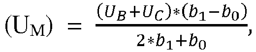
dans le cas d'un défaut de phase B ou d'un défaut de phase C, les tensions correspondantes des conducteurs de phase sains ininterrompus sont mesurées et utilisées pour calculer la tension de couplage capacitif (UM). - Appareil selon l'une quelconque des revendications 7 à 9, caractérisé en ce que lesdits facteurs sont sur base de la longueur et de la charge de la ligne de transmission, et/ou que lesdits facteurs sont ajustés dynamiquement sur la base de la longueur et de la charge de la ligne de transmission.
- Appareil selon la revendication 7, caractérisé en ce que ledit appareil peut distinguer un défaut permanent d'un défaut transitoire en cas de conversion de direction de flux de puissance de la ligne de transmission.
Applications Claiming Priority (1)
| Application Number | Priority Date | Filing Date | Title |
|---|---|---|---|
| PCT/CN2011/071887 WO2012122711A1 (fr) | 2011-03-17 | 2011-03-17 | Procédé à base de tension pour l'identification de défaut sur une ligne de transmission et appareil associé |
Publications (3)
| Publication Number | Publication Date |
|---|---|
| EP2686929A1 EP2686929A1 (fr) | 2014-01-22 |
| EP2686929A4 EP2686929A4 (fr) | 2014-11-12 |
| EP2686929B1 true EP2686929B1 (fr) | 2017-12-13 |
Family
ID=46830035
Family Applications (1)
| Application Number | Title | Priority Date | Filing Date |
|---|---|---|---|
| EP11861268.8A Active EP2686929B1 (fr) | 2011-03-17 | 2011-03-17 | Procédé à base de tension pour l'identification de défaut sur une ligne de transmission et appareil associé |
Country Status (5)
| Country | Link |
|---|---|
| US (1) | US10416221B2 (fr) |
| EP (1) | EP2686929B1 (fr) |
| CN (1) | CN103444037B (fr) |
| RU (1) | RU2546188C1 (fr) |
| WO (1) | WO2012122711A1 (fr) |
Families Citing this family (13)
| Publication number | Priority date | Publication date | Assignee | Title |
|---|---|---|---|---|
| CN104020342B (zh) | 2013-03-01 | 2017-03-01 | 西门子公司 | 流过断路器的电流方向判断方法及装置 |
| RU2660128C2 (ru) | 2014-02-21 | 2018-07-05 | Тзе Юаб Рисёрч Фаундэйшн | Способ обнаружения состояния обрыва фазы трансформатора |
| RU2565053C1 (ru) * | 2014-09-25 | 2015-10-20 | Открытое Акционерное Общество "Системный Оператор Единой Энергетической Системы" | Способ включения линии электропередачи переменного тока |
| US20160139212A1 (en) * | 2014-11-13 | 2016-05-19 | Eleon Energy, Inc. | Methods and systems for power restoration planning employing simulation and transient test analysis |
| CN106033894B (zh) * | 2015-03-20 | 2020-03-27 | 国家电网公司 | 判断特高压直流多落点电网稳定性的方法 |
| EP3136528B1 (fr) * | 2015-08-31 | 2020-04-22 | Siemens Aktiengesellschaft | Procede de protection differentielle, dispositif de protection differentielle et systeme de protection differentielle |
| CN107959276B (zh) * | 2017-12-22 | 2019-02-15 | 南京南瑞继保工程技术有限公司 | 一种单回线自适应重合闸方法 |
| CN110556789B (zh) * | 2018-05-31 | 2021-11-19 | 株洲中车时代电气股份有限公司 | 一种车载逆变器输出滤波电容的故障保护方法及系统 |
| CN111695089A (zh) * | 2020-06-12 | 2020-09-22 | 国网四川省电力公司电力科学研究院 | 一种基于多重分形谱的交流输电线路故障识别方法 |
| CN111884171B (zh) * | 2020-07-15 | 2021-05-28 | 华北电力大学 | 一种交直流系统的单相故障线路重合闸方法及系统 |
| CN113933707B (zh) * | 2021-10-12 | 2023-09-19 | 哈尔滨电机厂有限责任公司 | 一种发电机组故障原因判定可信度的自调节方法 |
| CN114089097B (zh) * | 2021-10-25 | 2024-09-06 | 珠海许继电气有限公司 | 配电线路接地故障性质识别及恢复方法 |
| CN116559598B (zh) * | 2023-07-10 | 2023-09-15 | 武汉创星空间科技发展有限公司 | 一种智慧配电网故障定位方法及系统 |
Family Cites Families (19)
| Publication number | Priority date | Publication date | Assignee | Title |
|---|---|---|---|---|
| US2147101A (en) * | 1936-05-06 | 1939-02-14 | Reyrolle A & Co Ltd | Electric protective arrangement |
| DE4439499C2 (de) * | 1994-10-27 | 1998-01-29 | Siemens Ag | Verfahren zum Erfassen eines Erdkurzschlusses auf einer elektrischen Energieübertragungsleitung |
| US5973899A (en) * | 1998-09-10 | 1999-10-26 | Pacificorp | Automated power feeder restoration system and method |
| SE525185C2 (sv) * | 2002-06-20 | 2004-12-21 | Abb Ab | Fellokalisering med hjälp av mätningar av ström och spänning från ena änden av en ledning |
| US6936779B2 (en) * | 2003-08-28 | 2005-08-30 | Hubbell Incorporated | Bypass recloser assembly |
| RU2254586C1 (ru) * | 2003-12-24 | 2005-06-20 | Новосибирский государственный технический университет | Способ определения фидера с однофазным дуговым замыканием на землю в радиальных распределительных кабельных сетях |
| CN100464475C (zh) | 2004-12-13 | 2009-02-25 | 天津大学 | 输电线路单相自适应重合闸综合判据实现方法 |
| CN101247040B (zh) * | 2008-02-29 | 2010-12-08 | 西安交通大学 | 一种带并联电抗器的输电线路永久性故障判别方法 |
| EP2113778B1 (fr) * | 2008-04-29 | 2017-12-06 | ABB Schweiz AG | Procédé et système de détermination de la localisation du défaut phase-phase ou triphasé |
| EP2139087B1 (fr) * | 2008-06-25 | 2016-10-19 | ABB Research LTD | Disjoncteur avec fonctionnalité de ré-enclenchement améliorée |
| EP2319151A4 (fr) * | 2008-08-29 | 2013-12-25 | Abb Research Ltd | Procede et appareil d' identification de defaillance dans une ligne de transmission electrique |
| CN100595991C (zh) | 2008-09-24 | 2010-03-24 | 天津大学 | 基于故障点电压的输电线路单相自适应重合闸实现方法 |
| WO2010148570A1 (fr) * | 2009-06-26 | 2010-12-29 | Abb Research Ltd. | Procédé d'identification de type de défaut de ligne électrique |
| KR101050605B1 (ko) * | 2009-08-07 | 2011-07-19 | 성균관대학교산학협력단 | 초전도 한류기를 고려한 재폐로 제어 시스템 및 그 제어 방법 |
| CN101877479A (zh) * | 2009-12-10 | 2010-11-03 | 贵州电力试验研究院 | 输电线路单相自适应重合闸相位比较判别方法 |
| CN101877480A (zh) * | 2009-12-10 | 2010-11-03 | 贵州电力试验研究院 | 输电线路单相自适应重合闸的电压补偿判别方法 |
| RU97873U1 (ru) * | 2010-04-30 | 2010-09-20 | Общество с ограниченной ответственностью "Научно-производственное предприятие "Резонанс" (ООО "НПП "Резонанс") | Устройство защиты генератора от замыканий на землю в обмотке статора |
| WO2012064386A1 (fr) * | 2010-11-10 | 2012-05-18 | Abb Research Ltd. | Dispositifs d'interruption de pannes et procédés de commande de ces derniers |
| US9276396B2 (en) * | 2012-02-17 | 2016-03-01 | General Electric Company | Power transmission fault analysis system and related method |
-
2011
- 2011-03-17 US US13/982,297 patent/US10416221B2/en active Active
- 2011-03-17 CN CN201180069380.9A patent/CN103444037B/zh active Active
- 2011-03-17 RU RU2013142282/07A patent/RU2546188C1/ru not_active IP Right Cessation
- 2011-03-17 WO PCT/CN2011/071887 patent/WO2012122711A1/fr not_active Ceased
- 2011-03-17 EP EP11861268.8A patent/EP2686929B1/fr active Active
Non-Patent Citations (1)
| Title |
|---|
| None * |
Also Published As
| Publication number | Publication date |
|---|---|
| CN103444037B (zh) | 2015-07-01 |
| RU2013142282A (ru) | 2015-03-27 |
| US20130317768A1 (en) | 2013-11-28 |
| RU2546188C1 (ru) | 2015-04-10 |
| EP2686929A1 (fr) | 2014-01-22 |
| US10416221B2 (en) | 2019-09-17 |
| WO2012122711A1 (fr) | 2012-09-20 |
| EP2686929A4 (fr) | 2014-11-12 |
| CN103444037A (zh) | 2013-12-11 |
Similar Documents
| Publication | Publication Date | Title |
|---|---|---|
| US10416221B2 (en) | Voltage based method for fault identification in a transmission line apparatus thereof | |
| CN103733458B (zh) | 并行传输线的距离保护的方法 | |
| EP0241832B1 (fr) | Procédé et dispositif destiné à la détection directionnelle d'un défaut sur une ligne de transmission de puissance | |
| Eissa et al. | A novel digital distance relaying technique for transmission line protection | |
| Bains et al. | Supplementary impedance-based fault-location algorithm for series-compensated lines | |
| US20190293705A1 (en) | Method, system and apparatus for fault detection | |
| US20190391191A1 (en) | A method and system for locating a fault in a mixed power transmission line | |
| EP3605765A1 (fr) | Identification de section défectueuse de ligne de transmission de puissance | |
| US7961445B2 (en) | Method of detecting fault extinction during a three-phase autoreclosing cycle in an AC transmission line | |
| Suryanarayana et al. | Directional relaying using parameter estimation approach | |
| Han et al. | Fault location on a mixed overhead and underground transmission feeder using a multiple-zone quadrilateral impedance relay and a double-ended travelling wave fault locator | |
| Mehrjerdi et al. | High-speed auxiliary fault location element for distance relays in double-circuit lines | |
| US20250321292A1 (en) | Method to detect single-phase-to-ground faults in electric power systems | |
| US20030074146A1 (en) | Crossover fault classification for power lines with parallel circuits | |
| US12362556B2 (en) | Single-ended broken conductor detection logic using incremental quantities | |
| CN103762567B (zh) | 基于故障位置因子的输电线路单相接地故障继电保护方法 | |
| JP4921246B2 (ja) | 地絡距離継電器 | |
| CN121079857A (zh) | 检测在ac电力传输系统中的传输线路中的故障的方法 | |
| Sidhu et al. | A numerical technique based on symmetrical components for protecting three-winding transformers | |
| US6741943B2 (en) | Crossover fault classification for power lines with parallel circuits | |
| US6721670B2 (en) | Crossover fault classification for power lines with parallel circuits | |
| Bhalja et al. | A New Digital Relaying Scheme for Parallel Transmission Line. | |
| Adewole | Investigation of methodologies for fault detection and diagnosis in electric power system protection | |
| Arias-Guzman et al. | Tensor Protection System Application in Transformer Protection | |
| Serpa et al. | Evaluation of cross-differential protection applied to double-circuit transmission lines under inter-circuit faults |
Legal Events
| Date | Code | Title | Description |
|---|---|---|---|
| PUAI | Public reference made under article 153(3) epc to a published international application that has entered the european phase |
Free format text: ORIGINAL CODE: 0009012 |
|
| 17P | Request for examination filed |
Effective date: 20130902 |
|
| AK | Designated contracting states |
Kind code of ref document: A1 Designated state(s): AL AT BE BG CH CY CZ DE DK EE ES FI FR GB GR HR HU IE IS IT LI LT LU LV MC MK MT NL NO PL PT RO RS SE SI SK SM TR |
|
| DAX | Request for extension of the european patent (deleted) | ||
| A4 | Supplementary search report drawn up and despatched |
Effective date: 20141010 |
|
| RIC1 | Information provided on ipc code assigned before grant |
Ipc: H02H 7/26 20060101AFI20141006BHEP Ipc: H02H 3/06 20060101ALI20141006BHEP Ipc: G01R 31/02 20060101ALI20141006BHEP |
|
| GRAP | Despatch of communication of intention to grant a patent |
Free format text: ORIGINAL CODE: EPIDOSNIGR1 |
|
| INTG | Intention to grant announced |
Effective date: 20170704 |
|
| RAP1 | Party data changed (applicant data changed or rights of an application transferred) |
Owner name: ABB SCHWEIZ AG |
|
| GRAS | Grant fee paid |
Free format text: ORIGINAL CODE: EPIDOSNIGR3 |
|
| GRAA | (expected) grant |
Free format text: ORIGINAL CODE: 0009210 |
|
| AK | Designated contracting states |
Kind code of ref document: B1 Designated state(s): AL AT BE BG CH CY CZ DE DK EE ES FI FR GB GR HR HU IE IS IT LI LT LU LV MC MK MT NL NO PL PT RO RS SE SI SK SM TR |
|
| REG | Reference to a national code |
Ref country code: GB Ref legal event code: FG4D |
|
| REG | Reference to a national code |
Ref country code: AT Ref legal event code: REF Ref document number: 955233 Country of ref document: AT Kind code of ref document: T Effective date: 20171215 Ref country code: CH Ref legal event code: EP |
|
| REG | Reference to a national code |
Ref country code: IE Ref legal event code: FG4D |
|
| REG | Reference to a national code |
Ref country code: DE Ref legal event code: R096 Ref document number: 602011044259 Country of ref document: DE |
|
| REG | Reference to a national code |
Ref country code: FR Ref legal event code: PLFP Year of fee payment: 8 |
|
| REG | Reference to a national code |
Ref country code: NL Ref legal event code: MP Effective date: 20171213 |
|
| REG | Reference to a national code |
Ref country code: LT Ref legal event code: MG4D |
|
| PG25 | Lapsed in a contracting state [announced via postgrant information from national office to epo] |
Ref country code: LT Free format text: LAPSE BECAUSE OF FAILURE TO SUBMIT A TRANSLATION OF THE DESCRIPTION OR TO PAY THE FEE WITHIN THE PRESCRIBED TIME-LIMIT Effective date: 20171213 Ref country code: FI Free format text: LAPSE BECAUSE OF FAILURE TO SUBMIT A TRANSLATION OF THE DESCRIPTION OR TO PAY THE FEE WITHIN THE PRESCRIBED TIME-LIMIT Effective date: 20171213 Ref country code: SE Free format text: LAPSE BECAUSE OF FAILURE TO SUBMIT A TRANSLATION OF THE DESCRIPTION OR TO PAY THE FEE WITHIN THE PRESCRIBED TIME-LIMIT Effective date: 20171213 Ref country code: NO Free format text: LAPSE BECAUSE OF FAILURE TO SUBMIT A TRANSLATION OF THE DESCRIPTION OR TO PAY THE FEE WITHIN THE PRESCRIBED TIME-LIMIT Effective date: 20180313 |
|
| REG | Reference to a national code |
Ref country code: AT Ref legal event code: MK05 Ref document number: 955233 Country of ref document: AT Kind code of ref document: T Effective date: 20171213 |
|
| PG25 | Lapsed in a contracting state [announced via postgrant information from national office to epo] |
Ref country code: GR Free format text: LAPSE BECAUSE OF FAILURE TO SUBMIT A TRANSLATION OF THE DESCRIPTION OR TO PAY THE FEE WITHIN THE PRESCRIBED TIME-LIMIT Effective date: 20180314 Ref country code: HR Free format text: LAPSE BECAUSE OF FAILURE TO SUBMIT A TRANSLATION OF THE DESCRIPTION OR TO PAY THE FEE WITHIN THE PRESCRIBED TIME-LIMIT Effective date: 20171213 Ref country code: RS Free format text: LAPSE BECAUSE OF FAILURE TO SUBMIT A TRANSLATION OF THE DESCRIPTION OR TO PAY THE FEE WITHIN THE PRESCRIBED TIME-LIMIT Effective date: 20171213 Ref country code: BG Free format text: LAPSE BECAUSE OF FAILURE TO SUBMIT A TRANSLATION OF THE DESCRIPTION OR TO PAY THE FEE WITHIN THE PRESCRIBED TIME-LIMIT Effective date: 20180313 Ref country code: LV Free format text: LAPSE BECAUSE OF FAILURE TO SUBMIT A TRANSLATION OF THE DESCRIPTION OR TO PAY THE FEE WITHIN THE PRESCRIBED TIME-LIMIT Effective date: 20171213 |
|
| PG25 | Lapsed in a contracting state [announced via postgrant information from national office to epo] |
Ref country code: NL Free format text: LAPSE BECAUSE OF FAILURE TO SUBMIT A TRANSLATION OF THE DESCRIPTION OR TO PAY THE FEE WITHIN THE PRESCRIBED TIME-LIMIT Effective date: 20171213 |
|
| PG25 | Lapsed in a contracting state [announced via postgrant information from national office to epo] |
Ref country code: SK Free format text: LAPSE BECAUSE OF FAILURE TO SUBMIT A TRANSLATION OF THE DESCRIPTION OR TO PAY THE FEE WITHIN THE PRESCRIBED TIME-LIMIT Effective date: 20171213 Ref country code: ES Free format text: LAPSE BECAUSE OF FAILURE TO SUBMIT A TRANSLATION OF THE DESCRIPTION OR TO PAY THE FEE WITHIN THE PRESCRIBED TIME-LIMIT Effective date: 20171213 Ref country code: CZ Free format text: LAPSE BECAUSE OF FAILURE TO SUBMIT A TRANSLATION OF THE DESCRIPTION OR TO PAY THE FEE WITHIN THE PRESCRIBED TIME-LIMIT Effective date: 20171213 Ref country code: CY Free format text: LAPSE BECAUSE OF FAILURE TO SUBMIT A TRANSLATION OF THE DESCRIPTION OR TO PAY THE FEE WITHIN THE PRESCRIBED TIME-LIMIT Effective date: 20171213 Ref country code: EE Free format text: LAPSE BECAUSE OF FAILURE TO SUBMIT A TRANSLATION OF THE DESCRIPTION OR TO PAY THE FEE WITHIN THE PRESCRIBED TIME-LIMIT Effective date: 20171213 |
|
| PG25 | Lapsed in a contracting state [announced via postgrant information from national office to epo] |
Ref country code: PL Free format text: LAPSE BECAUSE OF FAILURE TO SUBMIT A TRANSLATION OF THE DESCRIPTION OR TO PAY THE FEE WITHIN THE PRESCRIBED TIME-LIMIT Effective date: 20171213 Ref country code: RO Free format text: LAPSE BECAUSE OF FAILURE TO SUBMIT A TRANSLATION OF THE DESCRIPTION OR TO PAY THE FEE WITHIN THE PRESCRIBED TIME-LIMIT Effective date: 20171213 Ref country code: IT Free format text: LAPSE BECAUSE OF FAILURE TO SUBMIT A TRANSLATION OF THE DESCRIPTION OR TO PAY THE FEE WITHIN THE PRESCRIBED TIME-LIMIT Effective date: 20171213 Ref country code: IS Free format text: LAPSE BECAUSE OF FAILURE TO SUBMIT A TRANSLATION OF THE DESCRIPTION OR TO PAY THE FEE WITHIN THE PRESCRIBED TIME-LIMIT Effective date: 20180413 Ref country code: AT Free format text: LAPSE BECAUSE OF FAILURE TO SUBMIT A TRANSLATION OF THE DESCRIPTION OR TO PAY THE FEE WITHIN THE PRESCRIBED TIME-LIMIT Effective date: 20171213 Ref country code: SM Free format text: LAPSE BECAUSE OF FAILURE TO SUBMIT A TRANSLATION OF THE DESCRIPTION OR TO PAY THE FEE WITHIN THE PRESCRIBED TIME-LIMIT Effective date: 20171213 |
|
| REG | Reference to a national code |
Ref country code: DE Ref legal event code: R097 Ref document number: 602011044259 Country of ref document: DE |
|
| PLBE | No opposition filed within time limit |
Free format text: ORIGINAL CODE: 0009261 |
|
| STAA | Information on the status of an ep patent application or granted ep patent |
Free format text: STATUS: NO OPPOSITION FILED WITHIN TIME LIMIT |
|
| REG | Reference to a national code |
Ref country code: CH Ref legal event code: PL |
|
| 26N | No opposition filed |
Effective date: 20180914 |
|
| GBPC | Gb: european patent ceased through non-payment of renewal fee |
Effective date: 20180317 |
|
| PG25 | Lapsed in a contracting state [announced via postgrant information from national office to epo] |
Ref country code: MC Free format text: LAPSE BECAUSE OF FAILURE TO SUBMIT A TRANSLATION OF THE DESCRIPTION OR TO PAY THE FEE WITHIN THE PRESCRIBED TIME-LIMIT Effective date: 20171213 Ref country code: DK Free format text: LAPSE BECAUSE OF FAILURE TO SUBMIT A TRANSLATION OF THE DESCRIPTION OR TO PAY THE FEE WITHIN THE PRESCRIBED TIME-LIMIT Effective date: 20171213 |
|
| REG | Reference to a national code |
Ref country code: BE Ref legal event code: MM Effective date: 20180331 |
|
| REG | Reference to a national code |
Ref country code: IE Ref legal event code: MM4A |
|
| PG25 | Lapsed in a contracting state [announced via postgrant information from national office to epo] |
Ref country code: LU Free format text: LAPSE BECAUSE OF NON-PAYMENT OF DUE FEES Effective date: 20180317 |
|
| PG25 | Lapsed in a contracting state [announced via postgrant information from national office to epo] |
Ref country code: IE Free format text: LAPSE BECAUSE OF NON-PAYMENT OF DUE FEES Effective date: 20180317 |
|
| PG25 | Lapsed in a contracting state [announced via postgrant information from national office to epo] |
Ref country code: BE Free format text: LAPSE BECAUSE OF NON-PAYMENT OF DUE FEES Effective date: 20180331 Ref country code: SI Free format text: LAPSE BECAUSE OF FAILURE TO SUBMIT A TRANSLATION OF THE DESCRIPTION OR TO PAY THE FEE WITHIN THE PRESCRIBED TIME-LIMIT Effective date: 20171213 Ref country code: CH Free format text: LAPSE BECAUSE OF NON-PAYMENT OF DUE FEES Effective date: 20180331 Ref country code: GB Free format text: LAPSE BECAUSE OF NON-PAYMENT OF DUE FEES Effective date: 20180317 Ref country code: LI Free format text: LAPSE BECAUSE OF NON-PAYMENT OF DUE FEES Effective date: 20180331 |
|
| PG25 | Lapsed in a contracting state [announced via postgrant information from national office to epo] |
Ref country code: MT Free format text: LAPSE BECAUSE OF NON-PAYMENT OF DUE FEES Effective date: 20180317 |
|
| PG25 | Lapsed in a contracting state [announced via postgrant information from national office to epo] |
Ref country code: TR Free format text: LAPSE BECAUSE OF FAILURE TO SUBMIT A TRANSLATION OF THE DESCRIPTION OR TO PAY THE FEE WITHIN THE PRESCRIBED TIME-LIMIT Effective date: 20171213 |
|
| PG25 | Lapsed in a contracting state [announced via postgrant information from national office to epo] |
Ref country code: PT Free format text: LAPSE BECAUSE OF FAILURE TO SUBMIT A TRANSLATION OF THE DESCRIPTION OR TO PAY THE FEE WITHIN THE PRESCRIBED TIME-LIMIT Effective date: 20171213 Ref country code: HU Free format text: LAPSE BECAUSE OF FAILURE TO SUBMIT A TRANSLATION OF THE DESCRIPTION OR TO PAY THE FEE WITHIN THE PRESCRIBED TIME-LIMIT; INVALID AB INITIO Effective date: 20110317 |
|
| PG25 | Lapsed in a contracting state [announced via postgrant information from national office to epo] |
Ref country code: MK Free format text: LAPSE BECAUSE OF NON-PAYMENT OF DUE FEES Effective date: 20171213 |
|
| PG25 | Lapsed in a contracting state [announced via postgrant information from national office to epo] |
Ref country code: AL Free format text: LAPSE BECAUSE OF FAILURE TO SUBMIT A TRANSLATION OF THE DESCRIPTION OR TO PAY THE FEE WITHIN THE PRESCRIBED TIME-LIMIT Effective date: 20171213 |
|
| REG | Reference to a national code |
Ref country code: DE Ref legal event code: R081 Ref document number: 602011044259 Country of ref document: DE Owner name: HITACHI ENERGY SWITZERLAND AG, CH Free format text: FORMER OWNER: ABB SCHWEIZ AG, BADEN, CH Ref country code: DE Ref legal event code: R082 Ref document number: 602011044259 Country of ref document: DE Representative=s name: DENNEMEYER & ASSOCIATES RECHTSANWALTSGESELLSCH, DE Ref country code: DE Ref legal event code: R081 Ref document number: 602011044259 Country of ref document: DE Owner name: HITACHI ENERGY LTD, CH Free format text: FORMER OWNER: ABB SCHWEIZ AG, BADEN, CH Ref country code: DE Ref legal event code: R082 Ref document number: 602011044259 Country of ref document: DE Representative=s name: DENNEMEYER & ASSOCIATES S.A., DE Ref country code: DE Ref legal event code: R081 Ref document number: 602011044259 Country of ref document: DE Owner name: ABB POWER GRIDS SWITZERLAND AG, CH Free format text: FORMER OWNER: ABB SCHWEIZ AG, BADEN, CH |
|
| REG | Reference to a national code |
Ref country code: DE Ref legal event code: R081 Ref document number: 602011044259 Country of ref document: DE Owner name: HITACHI ENERGY SWITZERLAND AG, CH Free format text: FORMER OWNER: ABB POWER GRIDS SWITZERLAND AG, BADEN, CH Ref country code: DE Ref legal event code: R081 Ref document number: 602011044259 Country of ref document: DE Owner name: HITACHI ENERGY LTD, CH Free format text: FORMER OWNER: ABB POWER GRIDS SWITZERLAND AG, BADEN, CH |
|
| P01 | Opt-out of the competence of the unified patent court (upc) registered |
Effective date: 20230527 |
|
| REG | Reference to a national code |
Ref country code: DE Ref legal event code: R082 Ref document number: 602011044259 Country of ref document: DE Representative=s name: DENNEMEYER & ASSOCIATES RECHTSANWALTSGESELLSCH, DE Ref country code: DE Ref legal event code: R082 Ref document number: 602011044259 Country of ref document: DE Representative=s name: DENNEMEYER & ASSOCIATES S.A., DE Ref country code: DE Ref legal event code: R081 Ref document number: 602011044259 Country of ref document: DE Owner name: HITACHI ENERGY LTD, CH Free format text: FORMER OWNER: HITACHI ENERGY SWITZERLAND AG, BADEN, CH |
|
| REG | Reference to a national code |
Ref country code: DE Ref legal event code: R082 Ref document number: 602011044259 Country of ref document: DE Representative=s name: DENNEMEYER & ASSOCIATES RECHTSANWALTSGESELLSCH, DE |
|
| PGFP | Annual fee paid to national office [announced via postgrant information from national office to epo] |
Ref country code: DE Payment date: 20260319 Year of fee payment: 16 |
|
| PGFP | Annual fee paid to national office [announced via postgrant information from national office to epo] |
Ref country code: FR Payment date: 20260320 Year of fee payment: 16 |