EP2687078A1 - Machine de travail et manche de commande destiné à être fixé à celle-ci - Google Patents
Machine de travail et manche de commande destiné à être fixé à celle-ci Download PDFInfo
- Publication number
- EP2687078A1 EP2687078A1 EP12177261.0A EP12177261A EP2687078A1 EP 2687078 A1 EP2687078 A1 EP 2687078A1 EP 12177261 A EP12177261 A EP 12177261A EP 2687078 A1 EP2687078 A1 EP 2687078A1
- Authority
- EP
- European Patent Office
- Prior art keywords
- grip portion
- worker
- work machine
- degrees
- control handle
- Prior art date
- Legal status (The legal status is an assumption and is not a legal conclusion. Google has not performed a legal analysis and makes no representation as to the accuracy of the status listed.)
- Granted
Links
Images


Classifications
-
- A—HUMAN NECESSITIES
- A01—AGRICULTURE; FORESTRY; ANIMAL HUSBANDRY; HUNTING; TRAPPING; FISHING
- A01D—HARVESTING; MOWING
- A01D34/00—Mowers; Mowing apparatus of harvesters
- A01D34/835—Mowers; Mowing apparatus of harvesters specially adapted for particular purposes
- A01D34/90—Mowers; Mowing apparatus of harvesters specially adapted for particular purposes for carrying by the operator
- A01D34/902—Ergonomic provisions
-
- B—PERFORMING OPERATIONS; TRANSPORTING
- B25—HAND TOOLS; PORTABLE POWER-DRIVEN TOOLS; MANIPULATORS
- B25F—COMBINATION OR MULTI-PURPOSE TOOLS NOT OTHERWISE PROVIDED FOR; DETAILS OR COMPONENTS OF PORTABLE POWER-DRIVEN TOOLS NOT PARTICULARLY RELATED TO THE OPERATIONS PERFORMED AND NOT OTHERWISE PROVIDED FOR
- B25F5/00—Details or components of portable power-driven tools not particularly related to the operations performed and not otherwise provided for
- B25F5/02—Construction of casings, bodies or handles
Definitions
- the present invention relates to a work machine and a control handle to be mounted thereon, and typically relates to a brush cutter.
- Brush cutters are widely used for removing weeds, mowing undergrowth in forests and fields, and trimming shrubs.
- Brush cutters are composed of a power source, a rotating shaft driven by the power source, an operating pipe enclosing the rotating shaft and a rotary blade connected to a distal end of the rotating shaft.
- power sources they are roughly divided into those using internal combustion engines (for example, Japanese Patent Laid-open Publication No. hei 10-150825 ) and those using electric motors (for example, Japanese Patent Laid-open Publication No. 2012-55195 and USD 342,425)
- Blades for brush cutters widely range, depending on their intended use, and include nylon cutters with plural nylon-strings attached to spinning disks, metal blades having plural metal edges (for example, USD 493,476 ), chip saws with alloy chips embedded at distal ends of edges, circular saws (for example, USD 519,336 ), and so on.
- Brush cutters each have a control handle fixed to the operating pipe. Worker execute trimming with these brush cutters by manipulating the control handle and moving the operating pipe right and left in most cases. In this connection, there are various proposals related to such control handles.
- Japanese Patent Laid-open Publication No. hei 10-150825 and Japanese Patent Laid-open Publication No. 2012-55195 disclose left and right grip portions extending uprightly relative to control handles of brush cutters.
- Japanese Patent Laid-open Publication No. 2002-34315 proposes an control handle of a brush cutter in which a right grip portion to be grasped by the right hand extends uprightly and a left grip portion to be grasped by the left hand extends horizontally.
- Japanese Patent Laid-open Publication No. 2007-259721 proposes a control handle of a brush cutter that has a mechanism capable of changing right and left upright grip portions that slightly slant outward to become distant from each other toward their tops. This handle can be switched between a double-handed configuration requiring a worker to grasp the right and left grip portions with his right and left hands when manipulating the control handle and a single-handed configuration permitting a worker to grasp any one of the upright grip portions with any of his hands when manipulating the control handle.
- Japanese Patent Laid-open Publication No. 2007-89582 proposes a control handle of a backpack blower, vacuum or mist blower.
- This Japanese Patent Laid-open Publication No. 2007-89582 discloses a control handle that can be switched between a double-handed configuration and a single-handed configuration permitting a worker to grasp any one of the upright grip portions with any of his hands when manipulating the control handle.
- this existing proposal discloses that upright grip portions become closer to each other toward their tops. That is, this Japanese Patent Laid-open Publication No.
- 2007-89582 discloses grip portions in which, taking the right grip portion for explanation, it has a posture slightly slants to the left (inward) relative to a vertical line.
- This Japanese Patent Laid-open Publication No. 2007-89582 explicitly teaches that this angle of this inclination is approximately 20 degrees (approximately 70 degrees relative to a horizontal line).
- upright grip portion is used in this specification to generically call these types of grip portions having configurations standing upright or substantially upright even though slightly slanting outward or inward.
- FIG. 7 illustrates a right-side upright grip portion 1 grasped by a worker's right hand Rh.
- the worker's right hand Rh grasping the right-side upright grip portion 1 is oriented to locate its thumb 2 in an upper position and to face the back side 3 of the hand in the lateral outward direction.
- FIGS. 9 and 10 illustrate a posture of the right hand Rh taken when the worker has drawn his both hands on the upright grip portions 1 toward his body and moves the rotary blade upward.
- reference numeral 5 denotes a trigger lever for controlling the engine output
- reference numeral 6 indicates a throttle unlocking lever.
- a further object of the invention is to provide a work machine and a control handle to be mounted on the work machine, which enable a user of the work machine to proceed with his operation without the need for bending his upper body backward.
- the Inventor of the present application carefully observed workers in operation with work machines supported on harnesses the workers worn, and paid special attention to movements of their hands and postures of their arms they exhibited when drawing their hands put on grip portions toward their bodies to raise the distal ends of work machines.
- the present invention has been made from knowledge obtained therefrom.
- FIG. 8 shows positions of elbows of the worker when he pulls his hands toward the sides of his body to raise the rotary blade. From this illustration, it will be readily understand that the elbows are positioned very close to both sides of his body. That is, it is apparent from FIG. 8 that the worker behaves to tighten the arms to the sides of his body when he pulls his elbows to lift the rotary blade.
- the work machine has the grip portions one of which can be grasped by a worker's hand whose back side is faced upward, the worker can manipulate the control handle with a larger motion range of the joint of his wrist because the motion range of a wrist is larger in movement perpendicular to the surface of the palm of the corresponding hand than in movement parallel to the surface of the palm. Further, when the worker grasps the grip portion having the output control member and pulls the control handle toward his body, the worker's elbow draws back and away from the side of his body. When the worker moves the control handle up and down, his arm of the hand grasping the grip portion having the output control member exhibits a motion similar to that for rowing a boat afloat on water.
- the elbow corresponding to his subject hand moves away from one corresponding side of his body.
- the elbow EL of the worker if being average-sized, will be positioned apart from the corresponding side of his body by 200 mm or more. This value, however, varies with the worker's physical size.
- Inclination angle of the grip portion having the output control member thereon is preferably in the range larger than 25 degrees and not exceeding 70 degrees relative to a verttical line to allow easier movement of the worker's elbow away from the corresponding side of his body when he pulls the control handle with his hand grasping the grip portion having the output control member. This value of the inclination angle, however, may vary with the physical size of the worker.
- an inclination angle of the grip portion having the output control member in the range from 20 degrees to 40 degrees relative to a vertical line will ensure a drawback movement of the worker's elbow away from the corresponding side of his body when the worker pulls the control handle.
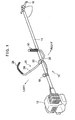
- FIG. 1 shows a brush cutter taken as an embodiment of the present invention.
- the brush cutter 10 like an existing one, has a power source 12, a rotary shaft to be driven rotationally by the power source 12 and a metal operating pipe 14 that covers the rotary shaft.
- the rotary shaft does not appear in the drawings for convenience of illustration.
- the brush cutter 10 further includes a rotary blade 16 as its cutter portion attached to a distal end of the operating pipe 14. The rotary blade 16 is connected to the power source 12 through the rotary shaft.
- the power source 12 used in this embodiment is a two-stroke internal combustion engine. Instead, a four-stroke internal combustion engine or an electric motor may be used.
- the rotary blade 16 An appropriate one of various known blades is selected as the rotary blade 16, depending on the environment where the brush cutter 10 should mainly be used.
- the embodiment shown here includes a shredder blade suitable for felling shrubby bushes.
- the brush cutter 10 of this embodiment bears a relatively large-scale engine. Therefore, a worker wears a shoulder harness on his upper body, and performs the intended cutting or trimming with the brush cutter 10 seized or hooked on the shoulder harness.
- a more simplified harness may be used instead of such a shoulder harness.
- a ring 18 is provided at a lengthwise intermediate position on the operating pipe 14 to hook the brush cutter 10 on the harness. This ring 18 engages a hook on the shoulder harness (hip pad).
- a control handle 20 is removably attached to a lengthwise intermediate portion of the operating pipe 14 of the brush cutter 10 with a bracket 22 that is a part of the control handle 20.
- the control handle 20 includes left and right independent metal handle pipes 24 and 26 that are fixed to the bracket 22.
- proximal ends of the left and right handle pipes 24, 26 are rotatable relative to the bracket 22 about their own axes to be variable in their angles. It is also acceptable to use an integral structure including left and right pipes 24, 26 altogether.
- the left and right handle pipes 24, 26 have grip portions 28 and 30 that are formed to extend upward by bending opposite free ends of the metal tubes (or tube) of the handle pipes 24, 26.
- the right grip portion 30 is provided, preferably on its front side (facing to the rotary blade 16), with a trigger lever (not shown for simplifying the illustration) which is an output control member for controlling the output of the engine 12.
- the right grip portion 30 has, preferably on its back face (facing to a worker in operation), a throttle unlocking lever 34. Positions of the trigger lever and the throttle unlocking lever 34, however, may be determined otherwise.
- the throttle unlocking lever 34 may be replaced with a throttle unlocking mechanism of a pushbutton type.
- the left and right grip portions 28 and 30 of the control handle 20 largely incline inward.
- the right grip 30 having the trigger lever thereon, it inclines inward by inclination angle ⁇ being approximately 30 degrees relative to a vertical line VL such that the worker's right hand Rh grasping the right grip portion is postured with its back 3 faced upward ( FIG. 4 ).
- the joint of its wrist 4 can move over a larger motion range in the vertical direction. Therefore, the worker can move the operating pipe 14 vertically about the ring 18 ( FIG. 1 ) in engagement with the hook of the shoulder harness as a pivotal axis by easily moving the back 3 of the right hand Rh vertically.
- the left grip portion 28 is different from the right grip portion 30 in having no throttle trigger (output control member). Therefore, the left grip portion 28 may be an upright grip portion as those used in conventional machines.
- the left grip portion 28 used in this embodiment includes, as shown in FIG. 2 , two grip sections, i.e. first and second grip sections 40, 42, and a curved transitional portion 44 between the first and second grip sections 40, 42.
- the first grip section 40 inclines inward by inclination angle ⁇ being approximately 15 degrees relative to the vertical line VL.
- the second grip section 42 that is the distal end of the left grip portion 28 inclines by ⁇ being 85 degrees relative to the vertical line VL.
- orientation of the second grip section 42 is approximately horizontal.
- distance D1 between the right grip portion 30 and the operating pipe 14 is approximately 200 mm.
- Distance D2 between the left grip portion 28 and the second grip section 42 is approximately 300 mm when viewed from above.
- the value of 200 mm as distances D1, D2 is relatively small, and this contributes to guiding backward movements of the right and left elbows EL of the worker away from the side of his body when pulling the control handle 20 toward the body.
- the inward inclination angle ⁇ of the right grip 30 having the trigger lever thereon may be 25 to 70 degrees when the distance D1 between the right grip portion 30 and the operating pipe 14 is relatively large.
- inward inclination angle ⁇ of the right grip 30 is preferably 25 to 50 degrees and more preferably 25 to 45 degrees. As far as the angle ⁇ is in these ranges, an ordinary worker in operation tends to face the back 3 of his right hand upward and draw his elbows EL away from the side of his body when he pulls his hands towards the body to lift up the rotary blade.
- the inward inclination angle ⁇ of the right grip portion 30 bearing the trigger lever thereon is in the range from 15 degrees to 45 degrees or preferably from 20 degrees to 40 degrees.
- the left grip portion 28 has the first and second grip sections 40, 42, different in angle of inclination as well as the curved transitional portion 44, the worker can grasp any of these grip sections easier to grasp in operation.
- the right grip portion 28, however, may be designed to incline by the same inclination angle as that of the right grip portion 30. It is recommended to determine the inclination angle ⁇ of the first left grip section 40 in the range from minus 10 degrees to 40 degrees, more preferably from 0 degrees to 30 degrees and most preferably from 10 degrees to 20 degrees.
- the inclination angle ⁇ of the second left grip section 42 is recommended to be in the range from 60 degrees to 90 degrees, more preferably from 70 degrees to 90 degrees and most preferably from 80 degrees to 90 degrees.
- FIG. 5 is a frontal view that shows a worker having pulled the left and right grip portions 28, 30 toward his body to raise the rotary blade 16 of the brush cutter 10.
- the shoulder harness is omitted from this illustration. It will be apparent from FIG. 5 that the elbows EL of the worker's arms Ar have been bent at positions apart from the sides of his body.
- the left and right grip portions 28, 30 are formed to largely incline inward, and this contributes to shortening the distances D1, D2 of the left and right grip portions 28, 30 from the operating pipe 14.
- the worker pulls his hands grasping the grip portions 28, 30 toward his body, it is ensured to guide the elbows EL of the worker's arms Ar away from the sides of his body to positions apart from the body by approximately 200 mm or more, although variable with the physical size of the worker.
- both arms Ar of the worker exhibit the same movement as that for oaring a boat on water.
- upright grip portions 1 FIG.
- the right grip portion 30 is inclined inward by a large angle, and the back 3 of his right hand grasping this grip portion 30 faces upward. Therefore, the worker can move the rotary blade 16 either vertically or horizontally by easily moving his wrist(s) with the larger motion range of the joint(s) of the wrist(s) 4 as already explained.
- the elbows of EL of his arms Ar are positioned apart from the sides of his body by 200 mm or more. Therefore, when he wants to move the rotary blade 16 vertically, he can move his arms Ar as if oaring a boat on water, and he can move the operating pipe 14 vertically and horizontally with these arms Ar ( FIG. 5 ). Accordingly, the worker no more needs to bend back his body especially when lifting the rotary blade 16, and can perform the cutting work while keeping a stable posture. In this case, of course, he can easily manipulate the trigger lever and the throttle unlocking lever 34 on the right grip portion 30.
- FIG. 6 shows at (I) that a longitudinal axis 30a of a cross-section of the right grip portion 30 is parallel to the operating pipe 14 ( FIG. 1 ). This is the essential configuration of the right grip portion 30 in existing machines.
- FIG. 6 further shows at (II) that the right grip portion 30 is mounted in an orientation with its longitudinal axis 30a being rotated outward by 20 degrees relative to the imaginary line parallel to the operating pipe 14.
- FIG. 6 further shows at (III) that the right grip portion 30 is mounted in an orientation with its longitudinal axis being rotated outward by 60 degrees relative to the imaginary line parallel to the operating pipe 14.
- the outward rotated status of the right grip portion 30 as shown in at (II) and (III) of FIG. 6 is herein called “outwardly opening configuration", and its angle is called “grip opening angle”.
- a problem with 0 degrees of the grip opening angle is that the back 3 of the hand tends to face outward and the wrist tends to bend inward. Accordingly, with the grip opening angle being 0 degrees, when the worker pulls the control handle 20 toward his body ( FIG. 2 ), his elbows EL are drawn apart from the sides of the body, but the wrists are liable to bend inward. In other words, when the grip opening angle is zero degrees, the back 3 of the hand tends to face outward, and this invites a narrower vertical motion range of the wrist. Therefore, when the worker lifts the rotary blade 16, a greater load is apt to be applied to the wrist.
- the back 3 of his hand faces upward.
- the worker since the wrist is already bent upward (toward the back 3 of the hand) before pulling the control handle 20, the worker will find it difficult to bend his wrist further upward when pulling the control handle toward his body because the upper part of the motion range of the wrist has been narrowed.
- his elbows EL tend to move closer to the sides of the body, and this tends to restrict his further motion for raising the control handle 20.
- the right hand grasping the right grip portion 30 exhibits a comfortable, easy aspect.
- the worker pulls the control handle 20 toward his body he may bend the elbows alone.
- the elbows EL tend to move away from the sides of the body, and the elbows tend to be guided to move away from the sides of the body without uneasy motions of the wrists.
- the grip portions 28, 30 (typically the right grip portion 30) to incline inward and to open outward, in whichever vertical level the worker has to manipulate the rotary blade 16, he can always keep the backs 3 of his hands faced upward and position the elbows EL outer than the grip portions 28, 30 in the same manner as he will use his arms when oaring a boat.
- the present invention is applicable not only to brush cutters but also to other work machines such as blowers, vacuum cleaners and sprayers.
Landscapes
- Life Sciences & Earth Sciences (AREA)
- Environmental Sciences (AREA)
- Engineering & Computer Science (AREA)
- Mechanical Engineering (AREA)
- Harvester Elements (AREA)
Priority Applications (2)
| Application Number | Priority Date | Filing Date | Title |
|---|---|---|---|
| EP12177261.0A EP2687078B1 (fr) | 2012-07-20 | 2012-07-20 | Machine de travail et manche de commande destiné à être fixé à celle-ci |
| ES12177261.0T ES2649575T3 (es) | 2012-07-20 | 2012-07-20 | Máquina de trabajo y manillar de control destinado a ser fijado a la misma |
Applications Claiming Priority (1)
| Application Number | Priority Date | Filing Date | Title |
|---|---|---|---|
| EP12177261.0A EP2687078B1 (fr) | 2012-07-20 | 2012-07-20 | Machine de travail et manche de commande destiné à être fixé à celle-ci |
Publications (2)
| Publication Number | Publication Date |
|---|---|
| EP2687078A1 true EP2687078A1 (fr) | 2014-01-22 |
| EP2687078B1 EP2687078B1 (fr) | 2017-08-30 |
Family
ID=47137466
Family Applications (1)
| Application Number | Title | Priority Date | Filing Date |
|---|---|---|---|
| EP12177261.0A Not-in-force EP2687078B1 (fr) | 2012-07-20 | 2012-07-20 | Machine de travail et manche de commande destiné à être fixé à celle-ci |
Country Status (2)
| Country | Link |
|---|---|
| EP (1) | EP2687078B1 (fr) |
| ES (1) | ES2649575T3 (fr) |
Cited By (6)
| Publication number | Priority date | Publication date | Assignee | Title |
|---|---|---|---|---|
| DE102018206177A1 (de) * | 2018-04-22 | 2019-10-24 | Robert Bosch Gmbh | Rasentrimmer oder Freischneider |
| WO2019206875A1 (fr) * | 2018-04-22 | 2019-10-31 | Robert Bosch Gmbh | Machine-outil à main, notamment taille-bordure ou scie de dégagement |
| WO2022030112A1 (fr) * | 2020-08-06 | 2022-02-10 | 株式会社東北設備 | Bande d'épaule et poignée pour suspendre un dispositif de coupe d'herbe du côté gauche du corps, et dispositif de coupe d'herbe les comprenant |
| WO2023149128A1 (fr) * | 2022-02-01 | 2023-08-10 | 株式会社東北設備 | Manche de débroussailleuse et ensemble débroussailleuse |
| US11785887B2 (en) | 2020-04-09 | 2023-10-17 | Andreas Stihl Ag & Co. Kg | Trimmer |
| US11864493B2 (en) | 2020-04-09 | 2024-01-09 | Andreas Stihl Ag & Co. Kg | Handle for a hand-guided power tool and trimmer |
Citations (11)
| Publication number | Priority date | Publication date | Assignee | Title |
|---|---|---|---|---|
| US4006528A (en) * | 1974-11-22 | 1977-02-08 | Kaaz Machinery Co. Ltd. | Portable grass and brush cutter with brake and clutch |
| USD342425S (en) | 1992-01-21 | 1993-12-21 | Ryobi Ltd. | Electric mower |
| JPH10150825A (ja) | 1996-11-26 | 1998-06-09 | Kioritz Corp | 携帯用刈払機 |
| JP2002034315A (ja) | 2000-07-19 | 2002-02-05 | Nikkari Co Ltd | 刈払機のハンドル装置 |
| USD493476S1 (en) | 2002-08-07 | 2004-07-27 | Andreas Stihl Ag & Co. Kg | Multi-bladed thicket knife |
| USD519336S1 (en) | 2005-01-14 | 2006-04-25 | Komatsu Zenoah Co. | Mowing machine |
| US20070067947A1 (en) * | 2005-09-28 | 2007-03-29 | Andreas Stihl Ag & Co., Kg | Implement |
| JP2007259721A (ja) | 2006-03-27 | 2007-10-11 | Tanaka Kogyo Kk | 刈払機 |
| WO2008076010A1 (fr) | 2006-12-20 | 2008-06-26 | Husqvarna Aktiebolag | Ensemble pour porter un outil portable entraîné par moteur sur un harnais |
| US20090277021A1 (en) * | 2008-05-07 | 2009-11-12 | Dolmar Gmbh | Portable implement |
| JP2012055195A (ja) | 2010-09-06 | 2012-03-22 | Maruyama Mfg Co Ltd | 携帯式作業機 |
-
2012
- 2012-07-20 EP EP12177261.0A patent/EP2687078B1/fr not_active Not-in-force
- 2012-07-20 ES ES12177261.0T patent/ES2649575T3/es active Active
Patent Citations (13)
| Publication number | Priority date | Publication date | Assignee | Title |
|---|---|---|---|---|
| US4006528A (en) * | 1974-11-22 | 1977-02-08 | Kaaz Machinery Co. Ltd. | Portable grass and brush cutter with brake and clutch |
| USD342425S (en) | 1992-01-21 | 1993-12-21 | Ryobi Ltd. | Electric mower |
| JPH10150825A (ja) | 1996-11-26 | 1998-06-09 | Kioritz Corp | 携帯用刈払機 |
| US6082087A (en) * | 1996-11-26 | 2000-07-04 | Kioritz Corporation | Portable trimmer and handle-bar therefor |
| JP2002034315A (ja) | 2000-07-19 | 2002-02-05 | Nikkari Co Ltd | 刈払機のハンドル装置 |
| USD493476S1 (en) | 2002-08-07 | 2004-07-27 | Andreas Stihl Ag & Co. Kg | Multi-bladed thicket knife |
| USD519336S1 (en) | 2005-01-14 | 2006-04-25 | Komatsu Zenoah Co. | Mowing machine |
| US20070067947A1 (en) * | 2005-09-28 | 2007-03-29 | Andreas Stihl Ag & Co., Kg | Implement |
| JP2007089582A (ja) | 2005-09-28 | 2007-04-12 | Andreas Stihl Ag & Co Kg | 作業機 |
| JP2007259721A (ja) | 2006-03-27 | 2007-10-11 | Tanaka Kogyo Kk | 刈払機 |
| WO2008076010A1 (fr) | 2006-12-20 | 2008-06-26 | Husqvarna Aktiebolag | Ensemble pour porter un outil portable entraîné par moteur sur un harnais |
| US20090277021A1 (en) * | 2008-05-07 | 2009-11-12 | Dolmar Gmbh | Portable implement |
| JP2012055195A (ja) | 2010-09-06 | 2012-03-22 | Maruyama Mfg Co Ltd | 携帯式作業機 |
Cited By (10)
| Publication number | Priority date | Publication date | Assignee | Title |
|---|---|---|---|---|
| DE102018206177A1 (de) * | 2018-04-22 | 2019-10-24 | Robert Bosch Gmbh | Rasentrimmer oder Freischneider |
| WO2019206875A1 (fr) * | 2018-04-22 | 2019-10-31 | Robert Bosch Gmbh | Machine-outil à main, notamment taille-bordure ou scie de dégagement |
| US11785887B2 (en) | 2020-04-09 | 2023-10-17 | Andreas Stihl Ag & Co. Kg | Trimmer |
| US11864493B2 (en) | 2020-04-09 | 2024-01-09 | Andreas Stihl Ag & Co. Kg | Handle for a hand-guided power tool and trimmer |
| US12349625B2 (en) | 2020-04-09 | 2025-07-08 | Andreas Stihl Ag & Co. Kg | Handle for a hand-guided power tool and trimmer |
| WO2022030112A1 (fr) * | 2020-08-06 | 2022-02-10 | 株式会社東北設備 | Bande d'épaule et poignée pour suspendre un dispositif de coupe d'herbe du côté gauche du corps, et dispositif de coupe d'herbe les comprenant |
| JP2022030126A (ja) * | 2020-08-06 | 2022-02-18 | 株式会社東北設備 | 草刈り機の左脇下吊り下げ用肩掛けバンド及びハンドル並びにこれらが装備される草刈り機 |
| JP7174957B2 (ja) | 2020-08-06 | 2022-11-18 | 株式会社東北設備 | 草刈り機用ハンドル及び草刈り機セット |
| WO2023149128A1 (fr) * | 2022-02-01 | 2023-08-10 | 株式会社東北設備 | Manche de débroussailleuse et ensemble débroussailleuse |
| JP2023112464A (ja) * | 2022-02-01 | 2023-08-14 | 株式会社東北設備 | 刈払機用ハンドル及び刈払機セット |
Also Published As
| Publication number | Publication date |
|---|---|
| ES2649575T3 (es) | 2018-01-12 |
| EP2687078B1 (fr) | 2017-08-30 |
Similar Documents
| Publication | Publication Date | Title |
|---|---|---|
| EP2687078B1 (fr) | Machine de travail et manche de commande destiné à être fixé à celle-ci | |
| EP2050327B1 (fr) | Coupeur de buissons | |
| JP3466843B2 (ja) | 携帯用刈払機 | |
| CN201830692U (zh) | 具有可旋转的后部把手的绿篱修剪器 | |
| US9192222B2 (en) | Backpack work machine | |
| EP2615904B1 (fr) | Dispositif de poignée pour outil électrique | |
| EP2845460B1 (fr) | Poignée pour machine de travail portative et débroussailleuse comprenant celle-ci | |
| US12349625B2 (en) | Handle for a hand-guided power tool and trimmer | |
| WO2015042457A1 (fr) | Configuration de poignée pour outils motorisés | |
| JP5490504B2 (ja) | 背負い式動力作業機 | |
| JP2010184304A (ja) | トップハンドル式携帯動力作業機 | |
| US7823652B2 (en) | Portable tool with a hand-gripped controller and method of using a portable powered tool | |
| CN201075905Y (zh) | 打草机 | |
| KR20200054509A (ko) | 예초기 | |
| WO2007069551A1 (fr) | Équipement d'inflexion et tondeuse portable équipée de celui-ci | |
| JP2013078268A (ja) | 刈払機 | |
| JPH0646256Y2 (ja) | 刈払機用ハンドル構造 | |
| JP4133361B2 (ja) | 携帯式動力刈払機 | |
| JP2016010397A (ja) | 草刈機および草刈機用回転刃 | |
| JP5199715B2 (ja) | 刈払機 | |
| US20260079520A1 (en) | Portable tool with grippable rear handle | |
| JP2008142072A (ja) | 傾斜地用肩掛式刈払機 | |
| US20240263526A1 (en) | Hand-held power tool | |
| JP3847245B2 (ja) | 携帯式作業機 | |
| CN101636075A (zh) | 具有握持装置的修草剪 |
Legal Events
| Date | Code | Title | Description |
|---|---|---|---|
| PUAI | Public reference made under article 153(3) epc to a published international application that has entered the european phase |
Free format text: ORIGINAL CODE: 0009012 |
|
| AK | Designated contracting states |
Kind code of ref document: A1 Designated state(s): AL AT BE BG CH CY CZ DE DK EE ES FI FR GB GR HR HU IE IS IT LI LT LU LV MC MK MT NL NO PL PT RO RS SE SI SK SM TR |
|
| AX | Request for extension of the european patent |
Extension state: BA ME |
|
| 17P | Request for examination filed |
Effective date: 20140722 |
|
| RBV | Designated contracting states (corrected) |
Designated state(s): AL AT BE BG CH CY CZ DE DK EE ES FI FR GB GR HR HU IE IS IT LI LT LU LV MC MK MT NL NO PL PT RO RS SE SI SK SM TR |
|
| GRAP | Despatch of communication of intention to grant a patent |
Free format text: ORIGINAL CODE: EPIDOSNIGR1 |
|
| STAA | Information on the status of an ep patent application or granted ep patent |
Free format text: STATUS: GRANT OF PATENT IS INTENDED |
|
| INTG | Intention to grant announced |
Effective date: 20170223 |
|
| GRAS | Grant fee paid |
Free format text: ORIGINAL CODE: EPIDOSNIGR3 |
|
| GRAA | (expected) grant |
Free format text: ORIGINAL CODE: 0009210 |
|
| STAA | Information on the status of an ep patent application or granted ep patent |
Free format text: STATUS: THE PATENT HAS BEEN GRANTED |
|
| AK | Designated contracting states |
Kind code of ref document: B1 Designated state(s): AL AT BE BG CH CY CZ DE DK EE ES FI FR GB GR HR HU IE IS IT LI LT LU LV MC MK MT NL NO PL PT RO RS SE SI SK SM TR |
|
| REG | Reference to a national code |
Ref country code: GB Ref legal event code: FG4D |
|
| REG | Reference to a national code |
Ref country code: CH Ref legal event code: EP |
|
| REG | Reference to a national code |
Ref country code: AT Ref legal event code: REF Ref document number: 922605 Country of ref document: AT Kind code of ref document: T Effective date: 20170915 |
|
| REG | Reference to a national code |
Ref country code: IE Ref legal event code: FG4D |
|
| REG | Reference to a national code |
Ref country code: DE Ref legal event code: R096 Ref document number: 602012036550 Country of ref document: DE |
|
| REG | Reference to a national code |
Ref country code: NL Ref legal event code: MP Effective date: 20170830 |
|
| REG | Reference to a national code |
Ref country code: LT Ref legal event code: MG4D |
|
| REG | Reference to a national code |
Ref country code: ES Ref legal event code: FG2A Ref document number: 2649575 Country of ref document: ES Kind code of ref document: T3 Effective date: 20180112 |
|
| REG | Reference to a national code |
Ref country code: AT Ref legal event code: MK05 Ref document number: 922605 Country of ref document: AT Kind code of ref document: T Effective date: 20170830 |
|
| PG25 | Lapsed in a contracting state [announced via postgrant information from national office to epo] |
Ref country code: AT Free format text: LAPSE BECAUSE OF FAILURE TO SUBMIT A TRANSLATION OF THE DESCRIPTION OR TO PAY THE FEE WITHIN THE PRESCRIBED TIME-LIMIT Effective date: 20170830 Ref country code: NO Free format text: LAPSE BECAUSE OF FAILURE TO SUBMIT A TRANSLATION OF THE DESCRIPTION OR TO PAY THE FEE WITHIN THE PRESCRIBED TIME-LIMIT Effective date: 20171130 Ref country code: SE Free format text: LAPSE BECAUSE OF FAILURE TO SUBMIT A TRANSLATION OF THE DESCRIPTION OR TO PAY THE FEE WITHIN THE PRESCRIBED TIME-LIMIT Effective date: 20170830 Ref country code: FI Free format text: LAPSE BECAUSE OF FAILURE TO SUBMIT A TRANSLATION OF THE DESCRIPTION OR TO PAY THE FEE WITHIN THE PRESCRIBED TIME-LIMIT Effective date: 20170830 Ref country code: LT Free format text: LAPSE BECAUSE OF FAILURE TO SUBMIT A TRANSLATION OF THE DESCRIPTION OR TO PAY THE FEE WITHIN THE PRESCRIBED TIME-LIMIT Effective date: 20170830 Ref country code: HR Free format text: LAPSE BECAUSE OF FAILURE TO SUBMIT A TRANSLATION OF THE DESCRIPTION OR TO PAY THE FEE WITHIN THE PRESCRIBED TIME-LIMIT Effective date: 20170830 |
|
| PG25 | Lapsed in a contracting state [announced via postgrant information from national office to epo] |
Ref country code: IS Free format text: LAPSE BECAUSE OF FAILURE TO SUBMIT A TRANSLATION OF THE DESCRIPTION OR TO PAY THE FEE WITHIN THE PRESCRIBED TIME-LIMIT Effective date: 20171230 Ref country code: RS Free format text: LAPSE BECAUSE OF FAILURE TO SUBMIT A TRANSLATION OF THE DESCRIPTION OR TO PAY THE FEE WITHIN THE PRESCRIBED TIME-LIMIT Effective date: 20170830 Ref country code: LV Free format text: LAPSE BECAUSE OF FAILURE TO SUBMIT A TRANSLATION OF THE DESCRIPTION OR TO PAY THE FEE WITHIN THE PRESCRIBED TIME-LIMIT Effective date: 20170830 Ref country code: BG Free format text: LAPSE BECAUSE OF FAILURE TO SUBMIT A TRANSLATION OF THE DESCRIPTION OR TO PAY THE FEE WITHIN THE PRESCRIBED TIME-LIMIT Effective date: 20171130 Ref country code: GR Free format text: LAPSE BECAUSE OF FAILURE TO SUBMIT A TRANSLATION OF THE DESCRIPTION OR TO PAY THE FEE WITHIN THE PRESCRIBED TIME-LIMIT Effective date: 20171201 |
|
| PG25 | Lapsed in a contracting state [announced via postgrant information from national office to epo] |
Ref country code: NL Free format text: LAPSE BECAUSE OF FAILURE TO SUBMIT A TRANSLATION OF THE DESCRIPTION OR TO PAY THE FEE WITHIN THE PRESCRIBED TIME-LIMIT Effective date: 20170830 |
|
| PG25 | Lapsed in a contracting state [announced via postgrant information from national office to epo] |
Ref country code: PL Free format text: LAPSE BECAUSE OF FAILURE TO SUBMIT A TRANSLATION OF THE DESCRIPTION OR TO PAY THE FEE WITHIN THE PRESCRIBED TIME-LIMIT Effective date: 20170830 Ref country code: RO Free format text: LAPSE BECAUSE OF FAILURE TO SUBMIT A TRANSLATION OF THE DESCRIPTION OR TO PAY THE FEE WITHIN THE PRESCRIBED TIME-LIMIT Effective date: 20170830 Ref country code: CZ Free format text: LAPSE BECAUSE OF FAILURE TO SUBMIT A TRANSLATION OF THE DESCRIPTION OR TO PAY THE FEE WITHIN THE PRESCRIBED TIME-LIMIT Effective date: 20170830 Ref country code: DK Free format text: LAPSE BECAUSE OF FAILURE TO SUBMIT A TRANSLATION OF THE DESCRIPTION OR TO PAY THE FEE WITHIN THE PRESCRIBED TIME-LIMIT Effective date: 20170830 |
|
| PG25 | Lapsed in a contracting state [announced via postgrant information from national office to epo] |
Ref country code: SM Free format text: LAPSE BECAUSE OF FAILURE TO SUBMIT A TRANSLATION OF THE DESCRIPTION OR TO PAY THE FEE WITHIN THE PRESCRIBED TIME-LIMIT Effective date: 20170830 Ref country code: IT Free format text: LAPSE BECAUSE OF FAILURE TO SUBMIT A TRANSLATION OF THE DESCRIPTION OR TO PAY THE FEE WITHIN THE PRESCRIBED TIME-LIMIT Effective date: 20170830 Ref country code: SK Free format text: LAPSE BECAUSE OF FAILURE TO SUBMIT A TRANSLATION OF THE DESCRIPTION OR TO PAY THE FEE WITHIN THE PRESCRIBED TIME-LIMIT Effective date: 20170830 Ref country code: EE Free format text: LAPSE BECAUSE OF FAILURE TO SUBMIT A TRANSLATION OF THE DESCRIPTION OR TO PAY THE FEE WITHIN THE PRESCRIBED TIME-LIMIT Effective date: 20170830 |
|
| REG | Reference to a national code |
Ref country code: DE Ref legal event code: R097 Ref document number: 602012036550 Country of ref document: DE |
|
| PLBE | No opposition filed within time limit |
Free format text: ORIGINAL CODE: 0009261 |
|
| STAA | Information on the status of an ep patent application or granted ep patent |
Free format text: STATUS: NO OPPOSITION FILED WITHIN TIME LIMIT |
|
| REG | Reference to a national code |
Ref country code: FR Ref legal event code: PLFP Year of fee payment: 7 |
|
| 26N | No opposition filed |
Effective date: 20180531 |
|
| PG25 | Lapsed in a contracting state [announced via postgrant information from national office to epo] |
Ref country code: SI Free format text: LAPSE BECAUSE OF FAILURE TO SUBMIT A TRANSLATION OF THE DESCRIPTION OR TO PAY THE FEE WITHIN THE PRESCRIBED TIME-LIMIT Effective date: 20170830 |
|
| REG | Reference to a national code |
Ref country code: CH Ref legal event code: PL |
|
| GBPC | Gb: european patent ceased through non-payment of renewal fee |
Effective date: 20180720 |
|
| PG25 | Lapsed in a contracting state [announced via postgrant information from national office to epo] |
Ref country code: MC Free format text: LAPSE BECAUSE OF FAILURE TO SUBMIT A TRANSLATION OF THE DESCRIPTION OR TO PAY THE FEE WITHIN THE PRESCRIBED TIME-LIMIT Effective date: 20170830 Ref country code: LU Free format text: LAPSE BECAUSE OF NON-PAYMENT OF DUE FEES Effective date: 20180720 |
|
| REG | Reference to a national code |
Ref country code: BE Ref legal event code: MM Effective date: 20180731 |
|
| REG | Reference to a national code |
Ref country code: IE Ref legal event code: MM4A |
|
| PG25 | Lapsed in a contracting state [announced via postgrant information from national office to epo] |
Ref country code: LI Free format text: LAPSE BECAUSE OF NON-PAYMENT OF DUE FEES Effective date: 20180731 Ref country code: GB Free format text: LAPSE BECAUSE OF NON-PAYMENT OF DUE FEES Effective date: 20180720 Ref country code: IE Free format text: LAPSE BECAUSE OF NON-PAYMENT OF DUE FEES Effective date: 20180720 Ref country code: CH Free format text: LAPSE BECAUSE OF NON-PAYMENT OF DUE FEES Effective date: 20180731 |
|
| PG25 | Lapsed in a contracting state [announced via postgrant information from national office to epo] |
Ref country code: BE Free format text: LAPSE BECAUSE OF NON-PAYMENT OF DUE FEES Effective date: 20180731 |
|
| PG25 | Lapsed in a contracting state [announced via postgrant information from national office to epo] |
Ref country code: MT Free format text: LAPSE BECAUSE OF NON-PAYMENT OF DUE FEES Effective date: 20180720 |
|
| PG25 | Lapsed in a contracting state [announced via postgrant information from national office to epo] |
Ref country code: TR Free format text: LAPSE BECAUSE OF FAILURE TO SUBMIT A TRANSLATION OF THE DESCRIPTION OR TO PAY THE FEE WITHIN THE PRESCRIBED TIME-LIMIT Effective date: 20170830 |
|
| PG25 | Lapsed in a contracting state [announced via postgrant information from national office to epo] |
Ref country code: HU Free format text: LAPSE BECAUSE OF FAILURE TO SUBMIT A TRANSLATION OF THE DESCRIPTION OR TO PAY THE FEE WITHIN THE PRESCRIBED TIME-LIMIT; INVALID AB INITIO Effective date: 20120720 Ref country code: PT Free format text: LAPSE BECAUSE OF FAILURE TO SUBMIT A TRANSLATION OF THE DESCRIPTION OR TO PAY THE FEE WITHIN THE PRESCRIBED TIME-LIMIT Effective date: 20170830 |
|
| PG25 | Lapsed in a contracting state [announced via postgrant information from national office to epo] |
Ref country code: CY Free format text: LAPSE BECAUSE OF FAILURE TO SUBMIT A TRANSLATION OF THE DESCRIPTION OR TO PAY THE FEE WITHIN THE PRESCRIBED TIME-LIMIT Effective date: 20170830 Ref country code: MK Free format text: LAPSE BECAUSE OF NON-PAYMENT OF DUE FEES Effective date: 20170830 |
|
| PG25 | Lapsed in a contracting state [announced via postgrant information from national office to epo] |
Ref country code: AL Free format text: LAPSE BECAUSE OF FAILURE TO SUBMIT A TRANSLATION OF THE DESCRIPTION OR TO PAY THE FEE WITHIN THE PRESCRIBED TIME-LIMIT Effective date: 20170830 |
|
| PGFP | Annual fee paid to national office [announced via postgrant information from national office to epo] |
Ref country code: FR Payment date: 20210729 Year of fee payment: 10 |
|
| PGFP | Annual fee paid to national office [announced via postgrant information from national office to epo] |
Ref country code: DE Payment date: 20210721 Year of fee payment: 10 Ref country code: ES Payment date: 20210927 Year of fee payment: 10 |
|
| REG | Reference to a national code |
Ref country code: DE Ref legal event code: R119 Ref document number: 602012036550 Country of ref document: DE |
|
| PG25 | Lapsed in a contracting state [announced via postgrant information from national office to epo] |
Ref country code: FR Free format text: LAPSE BECAUSE OF NON-PAYMENT OF DUE FEES Effective date: 20220731 |
|
| PG25 | Lapsed in a contracting state [announced via postgrant information from national office to epo] |
Ref country code: DE Free format text: LAPSE BECAUSE OF NON-PAYMENT OF DUE FEES Effective date: 20230201 |
|
| REG | Reference to a national code |
Ref country code: ES Ref legal event code: FD2A Effective date: 20230905 |
|
| PG25 | Lapsed in a contracting state [announced via postgrant information from national office to epo] |
Ref country code: ES Free format text: LAPSE BECAUSE OF NON-PAYMENT OF DUE FEES Effective date: 20220721 |