EP2687112A2 - Espacement de segments de tiges de filtre - Google Patents
Espacement de segments de tiges de filtre Download PDFInfo
- Publication number
- EP2687112A2 EP2687112A2 EP13175022.6A EP13175022A EP2687112A2 EP 2687112 A2 EP2687112 A2 EP 2687112A2 EP 13175022 A EP13175022 A EP 13175022A EP 2687112 A2 EP2687112 A2 EP 2687112A2
- Authority
- EP
- European Patent Office
- Prior art keywords
- article
- segment
- staggering
- article segment
- subgroup
- Prior art date
- Legal status (The legal status is an assumption and is not a legal conclusion. Google has not performed a legal analysis and makes no representation as to the accuracy of the status listed.)
- Granted
Links
Images



Classifications
-
- A—HUMAN NECESSITIES
- A24—TOBACCO; CIGARS; CIGARETTES; SIMULATED SMOKING DEVICES; SMOKERS' REQUISITES
- A24C—MACHINES FOR MAKING CIGARS OR CIGARETTES
- A24C5/00—Making cigarettes; Making tipping materials for, or attaching filters or mouthpieces to, cigars or cigarettes
- A24C5/47—Attaching filters or mouthpieces to cigars or cigarettes, e.g. inserting filters into cigarettes or their mouthpieces
- A24C5/478—Transport means for filter- or cigarette-rods in view of their assembling
-
- A—HUMAN NECESSITIES
- A24—TOBACCO; CIGARS; CIGARETTES; SIMULATED SMOKING DEVICES; SMOKERS' REQUISITES
- A24D—CIGARS; CIGARETTES; TOBACCO SMOKE FILTERS; MOUTHPIECES OF CIGARS OR CIGARETTES; MANUFACTURE OF TOBACCO SMOKE FILTERS OR MOUTHPIECES
- A24D3/00—Tobacco smoke filters, e.g. filter tips or filtering inserts; Filters specially adapted for simulated smoking devices; Mouthpieces of cigars or cigarettes
- A24D3/02—Manufacture of tobacco smoke filters
- A24D3/0275—Manufacture of tobacco smoke filters for filters with special features
- A24D3/0287—Manufacture of tobacco smoke filters for filters with special features for composite filters
Definitions
- the invention relates to a method for staggering rod-shaped article segments of the tobacco processing industry, in particular filter rod segments, each article segment groups each with more than two longitudinally juxtaposed article segments in transverse axial conveying direction groups by means of a conveying member, in particular conveyor drum, a staggering device for staggering the article segments supplied become.
- multi-segment filters consisting of different filter segments, such as different materials. These materials are, for example, cellulose acetate, paper, fluid, granules, sintered elements, hollow cylinders or hollow chambers, capsules and the like.
- Such multi-segment filters composed of several filter segments, which also include the term "multiple filter" After forming groups of filter segments, for example, they are wrapped in a continuous process with wrapping material, such as paper, for example, and then divided into, in particular multi-long, multi-segment filter rods in order to be further processed.
- the group forming device comprises two magazines for filter rods, wherein the multiply long filter rods are removed from the magazines individually, cut into filter segments and different cut filter segments are grouped together.
- a device or machine of this type of HAUNI Maschinenbau AG, Hamburg, for the production of multi-segment filters with two different filter components is known under the name MULFI, wherein the devices may further also have a corresponding strand-forming device and / or a group-forming device.
- Articles of the tobacco processing industry are understood in the present context to mean those products which, in one or more parallel rows, are conveyed on conveyors, e.g. on conveyor drums in filter or cigarette manufacturing machines, held and by these, preferably transaxially conveyed.
- Such articles are filter cigarettes as well as filter rods, filter segments, etc. If, for the sake of simplicity, only filter rods or filter segments are discussed below, then what has been said also applies correspondingly to other articles of the aforementioned type to be conveyed.
- the object of the invention is to provide article segments of the tobacco processing industry when staggering, in particular narrow, article segments, such as e.g. Filter rod segments, safe to handle.
- the invention is based on the idea that when staggering article segments, e.g. Filter bar segments, a filter bar segment or multiple filter bar segments as an article segment subgroup on the staggering device, in particular staggering drum, staggered, with an article segment subgroup being arranged in a staging step as a second article segment subgroup after the first article segment subgroup in the subsequent stub of the staggering device that is not immediately adjacent to the first item subgroup taken from the provided article segment group is arranged on the transferring conveying member.
- article segments e.g. Filter bar segments, a filter bar segment or multiple filter bar segments as an article segment subgroup on the staggering device, in particular staggering drum, staggered
- filter segments which are also referred to as filter rod segments are conveyed in the arrangement segment 1 - segment 2 - segment 3 - segment 4 on a conveyor drum to a staggering drum as segment group to be staggered.
- segment 2 is first taken between segment 1 and segment 3.
- Segment 2 forms the article segment subgroup arranged on the staggering drum.
- the segment 1 and segment 3 adjacent to the removed segment 2 are not transferred to the staggering drum. Rather, that's about one Segment length to segment 2 spaced outer segment 4 arranged after the transferred segment 2 of the segment group on the staggering drum.
- segment 4 is spaced from the spaced segment 1 on the staggering drum.
- segment 3 is arranged as the last segment subgroup on the staggering drum.
- the segment subgroups are staggered in the following order: Segment 2 - Segment 4 - Segment 1 - Segment 3.
- segment subgroups are not moved in the longitudinal axial direction, so that the On the staggering drum arranged in succession staggered segments are not aligned in the longitudinal axial direction and thus in the longitudinal axial direction also have the same distances as on the preceding conveyor organ on which the article group was provided with the segments.
- each article segment subgroup is staggered to consist of one filter segment or of several filter segments, wherein in particular when several filter segments are provided for an article segment subgroup, the article segment subgroups each have the same or approximately the same number of article segments.
- the number of article segments of a Article segment subset preferably differs by one article segment from the number of article segments of a second or another article segment subset.
- an article group with seven article segments i. with an odd number of article segments promoted to staggering a staggering facility
- an article group with eleven adjacently arranged article segments is conveyed to the staggering device, it is possible to arrange two article segment subgroups, each with four article segments, and one article segment subgroup with three article segments staggered on the staggering device one behind the other.
- the article segment subsets are unequal, i.
- a staggering drum with an uneven pitch i. used or used with an uneven pitch between the receiving troughs of the staggering drum.
- the third tiered segment subgroup segment 1 is spaced two lengths of equally sized segments with respect to the second segment segment transferring segment 4.
- This method step is also carried out, for example, according to the above four-segment embodiment, since the fourth staggered article segment group segment 3 is spaced by an article segment subgroup length to the third previously transmitted article segment subgroup segment 1 in the longitudinal axial direction.
- At least two staggering process steps are carried out in which staggered article segment subgroups are taken from the article group provided, which was previously on the staggering drum arranged article segment subgroup in the longitudinal axial direction is spaced by at least a length of the article segment subgroups.
- this process step of sequential staggering is carried out a total of three times.
- these two article segment subgroups are or will be in the longitudinal axial direction and at least one or more lengths of the article segment subgroups arranged on the staggering device or the staggering drum.
- a development of the method is characterized in that prior to the transfer to the first relaying device, the first article segment subgroup to be staggered or staggered and / or the third article segment subgroup to be staggered or staggered are formed as an article segment subgroup between the two outer article segment subgroups of the article segment group.
- the recording of a first segment subgroup on the staggering drum between the two outer article segment subgroups takes place, for example, in the case of a four-segment article segment group on the conveying element arranged in the staggering device and conveying the article segment groups.
- the removal or transfer of a first and third article segment subgroup in the order of staggering between outer or outer article segment subgroups can take place, for example, in a five-segment article segment group.
- the staggering device has one, preferably only one, staggering drum for carrying out the method steps.
- the only one staggering drum for example, in a four-segment article segment group or an article segment group having more than four article segments, the longitudinal axial spacing on the staggering drum between two staggered successively arranged article segment subgroups executed.
- two segment subgroups are conveyed to a further staggering drum for sequential staggering.
- at least one further conveying member in particular a further conveying drum, for conveying the article segment sub-groups in a transverse-axial direction.
- the two article segments of each article segment subgroup are arranged staggered in succession by a further staggering process in two different receiving troughs of the staggering device.
- this method step it is possible, for example, to stagger on a first staggered drum three article segment subgroups arranged in each case with three article segments and then by means of the downstream second staggering drum the individual item segments of the staggered article segment subgroups individually staggered and singled on the second staggered drum, wherein the staggering process on the second staggering drum the individual article segments of the article segment subgroups are staggered, wherein in a step two spaced apart by an article segment length article segments from each other in the longitudinal axial direction spaced on the second conveyor drum are arranged staggered.
- a preferred embodiment is characterized in that, prior to the transfer to the second staggering device, the first article segment is formed between the two outer article segments of the respective article segment subgroup.
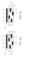
- FIGS. 1a, 1b two exemplary embodiments for staggering filter segments on a schematically designated staggering drum 10 are each shown in a flowchart.
- the staggering drum 10 is conveyed by means of a conveyor drum arranged on the staggering drum 10 to an article group 100 consisting of three filter segments F1, F2, F3.
- the filter segments F1, F2, F3 of an article group 100 are arranged side by side in the respective receptacles of the conveyor drum in the longitudinal axial direction and are in succession and in the longitudinal axial direction during or after transfer to the staggering drum 10 in the recordings A1, A2, A3 of the staggering drum arranged offset staggered to each other.
- the staggering drum 10 relative to the transverse axial conveying direction T for receiving the individual Filter segments F1, F2, F3 as article segment subgroup recordings A1, A2 and A3 on.
- the filter segment F3 of the article group 100 is received in the first recording A1 of the staggering drum 10 in the conveying direction T. Subsequently, in the subsequent recording A2 of the staggering drum 10 relative to the transverse axial conveying direction T, the filter segment F1, which is spaced by a filter segment length (or article segment subgroup length) from the removed filter segment F3, is received. Subsequently, the remaining middle filter segment F2 is received in the receptacles A3 of the staggering drum 10.
- the outer filter segment F1 of the article group 100 is first of all taken up in the first receptacle A1 of the staggering drum 10, the filter segment F3, which is spaced apart by a filter segment length from the filter segment F1, being subsequently taken into the subsequent second receptacle A2 of the staggering drum 10. Subsequently, the remaining middle filter segment F3 is arranged in the receptacle A3 of the staggering drum 10.
- the individual segments of the article groups 100 consisting of four filter segments F1, F2, F3, F4 staggered on the staggering drum 10.
- the filter segments F1, F2, F3, F4 are conveyed by a conveyor drum to the staggering drum 10, wherein the filter segments F1, F2, F3, F4 are arranged side by side in the respective receptacles of the conveyor drum in the longitudinal axial direction.
- the individual filter segments F1, F2, F3, F4 are singled on the receptacles A1 to A4 of the staggering drum 10 and arranged in staggered fashion one behind the other.
- the successively arranged filter segments F1, F2, F3, F4 are arranged in the receptacles A1, A2, A3, A4 such that two filter segments in adjacent receiving troughs of the staggering drum 10 are spaced apart by at least one filter segment length in the longitudinal axial direction.
- the filter segments F2, F4 in the receptacles A1, A2 and the filter segments F1, F3 in the receptacles A3, A4 each staggered by a filter segment length in the longitudinal axial direction arranged one behind the other.
- the filter segments F4 and F1 in the receptacles A2 and A3 are arranged in the longitudinal axial direction staggered by two filter segment lengths in the longitudinal axial direction of each other.
- Fig. 2b are also the previously immediately adjacent filter segments F1, F2, F3, F4 on the article group 100 zu adjden conveyor drum when staggered on the staggering drum 10 in the receiving cavities A1 to A4 arranged such that the staggered filter segments each by at least one filter segment length in the longitudinal axial direction with respect are spaced on the arranged in the adjacent receptacles filter segments.
- the filter segments F3 and F1 are in the adjacent, in the conveying direction T successively arranged receptacles A1, A2 spaced by a filter segment length in the longitudinal axial direction. This also applies to the filter segments F1 and F2 recorded in the subsequent photographs A3 and A4.
- the filter segments F1 and F4 in the immediately successively arranged recordings A2 and A3 are spaced apart by two filter segment lengths in the longitudinal axial direction.
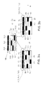
- FIG. 3a and 3b Two different embodiments for staggering article segments twice are shown schematically in a flowchart.
- two staggering drums 10, 20 are arranged in a transverse axial conveying direction T one behind the other.
- a plurality of filter segment subgroups FU1, FU2, FU3 of the article group 100 to the staggering drum 10 are conveyed to the first staggering drum 10, so that the filter segment subgroups FU1, FU2, FU3 as article segment subgroups in a staggered manner in the images A1, A2 and A3 of the staggering drum 10 are arranged.
- the filter segment subgroups FU3, FU1 are spaced apart in the longitudinal axial direction by a length of an article segment subgroup, the filter segment subgroups FU3, FU1 being arranged in two receptacles A1, A2 arranged one behind the other.
- each filter segment subgroup FU1, FU2, FU3 has four filter segments F1, F2, F3, F4 arranged side by side in the longitudinal axial direction as individual or separated article segments.
- the filter segments F1 to F4 of the filter segment subgroups FU1 to FU3 thereby form (filter segment) sub-subgroups of the filter segment subgroup FU1 to FU3.
- the staggered successively arranged filter segment subgroups FU3, FU1 and FU2 on the first staggering drum 10 are subsequently each passed to the second staggering drum 20, wherein the filter segments F1, F2, F3, F4, which in the FIGS. 3a, 3b are reproduced in an enlarged, not to scale representation, in each case on the subsequent second staggering drum 20 according to the in the FIGS. 3a, 3b illustrated embodiments staggered in the respective recordings B1 to B4 of the staggering drum 20 (analogous to embodiments in Fig. 2a, 2b ) to be ordered.
- the filter segments F1 to F4 of the filter segment subgroup FU3 are arranged in the receptacle A1 by at least one length of the filter segment subgroups to the filter segments of the filter segments of the filter segment subgroup FU1 arranged staggered in the receptacle A2 of the staggering drum 10. Subsequently, within the respective filter segment subgroups FU3, FU2, FU1, the filter segments F1 to F4 are spaced apart by at least one filter segment length in the receptacles B1 to B4 of the second staggering drum 20.
- FIGS. 4a, 4b Further exemplary embodiments of a flow chart for staggering filter segments twice by means of two successively arranged staggering drums 10, 20 are shown schematically. Compared to the embodiments in Fig. 3a, 3b In each case, four filter segment sub-groups FU1, FU2, FU3, FU4 arranged side by side are conveyed to the first staggering drum 10 as an article group, wherein the filter segment subgroups, for example, according to the in Fig.
- FIGS. 4a, 4b schematically shows enlarged representations of the respective filter segment subgroups FU3 (as well as FU1, FU2, FU4) between the staggering drums 10 and 20, each filter segment subgroup consisting of three adjacently arranged filter segments F1, F2, F3 (as individual or singulated article segments).
- the filter segments F1, F2, F3 of the respective filter segment subgroups FU1 to FU4 are transferred in a staggered manner to the next, second staggering drum 20 and arranged staggered correspondingly in the receptacles B1 to B3.
- the filter segments are staggered at least twice on the staggered drums 10, 20, the staggered filter segment subgroups FU1 to FU4 and the filter segments F1 to F3 of the filter segment subgroups FU1 being staggered on each staggering drum at staggering are spaced at least once on each staggering drum 10, 20 such that in the longitudinal axial direction a pair of filter segment subgroups or a pair of filter segments in the longitudinal axial direction by a length of a filter segment subassembly or by the length of a filter segment on the adjacent receptacles of the staking drum 10, 20 staggered and spaced.
- staggering of the stubble drums adjacent filter segments or filter segment subgroups are not transferred to successive receiving troughs of the staggering drum.
- short filter segments for example with a length of 8 to 15 mm or with a maximum length of 8 to 15 mm
- a process-reliable staggering of the segments is achieved.
- filter segments for an article group designed this on the first staggering drum Providing 7, 8, 9, 10, 11, and 12 filter segments prior to staggering, these are staggered onto two consecutive stomp rolls, with the filter segments being singularly delivered to a subsequent conveyor drum after staggering.
- Fig. 5 For example, the staggering arrangement of five article segments S1, S2, S3, S4, S5 is shown on a staggering drum 10, the article segments S1 to S5 being staggered in the stubs A1 to A5.
- the article segments S1 to S5 may be isolated segments, eg filter segments, or a group of segments. It is crucial that between two arranged in the conveying direction one behind the other in the receiving cavities A1 to A5 article segments two directly transversely spaced article segments are arranged offset by at least one length of the article segment in the longitudinal axial direction. Due to the fivefold staggering of the five article segments S1 to S5, this results in a total of fourteen ways to space the article segments S1 to S5 correspondingly on a staggering drum without two directly adjoining article segments being not spaced apart in the longitudinal axial direction.
Landscapes
- Cigarettes, Filters, And Manufacturing Of Filters (AREA)
- Manufacturing Of Cigar And Cigarette Tobacco (AREA)
- Combined Means For Separation Of Solids (AREA)
- Sorting Of Articles (AREA)
Priority Applications (1)
| Application Number | Priority Date | Filing Date | Title |
|---|---|---|---|
| PL13175022T PL2687112T3 (pl) | 2012-07-19 | 2013-07-04 | Kaskadowe rozmieszczanie segmentów sztabek filtrowych |
Applications Claiming Priority (1)
| Application Number | Priority Date | Filing Date | Title |
|---|---|---|---|
| DE102012212737.2A DE102012212737A1 (de) | 2012-07-19 | 2012-07-19 | Staffeln von Filterstabsegmenten |
Publications (3)
| Publication Number | Publication Date |
|---|---|
| EP2687112A2 true EP2687112A2 (fr) | 2014-01-22 |
| EP2687112A3 EP2687112A3 (fr) | 2015-09-09 |
| EP2687112B1 EP2687112B1 (fr) | 2017-09-06 |
Family
ID=48875491
Family Applications (1)
| Application Number | Title | Priority Date | Filing Date |
|---|---|---|---|
| EP13175022.6A Not-in-force EP2687112B1 (fr) | 2012-07-19 | 2013-07-04 | Espacement de segments de tiges de filtre |
Country Status (4)
| Country | Link |
|---|---|
| EP (1) | EP2687112B1 (fr) |
| CN (1) | CN103564653B (fr) |
| DE (1) | DE102012212737A1 (fr) |
| PL (1) | PL2687112T3 (fr) |
Families Citing this family (1)
| Publication number | Priority date | Publication date | Assignee | Title |
|---|---|---|---|---|
| DE102021110510A1 (de) * | 2021-04-23 | 2022-10-27 | Hauni Maschinenbau Gmbh | Verfahren zum Herstellen von Multisegmentartikeln |
Citations (3)
| Publication number | Priority date | Publication date | Assignee | Title |
|---|---|---|---|---|
| DE2452749A1 (de) | 1974-11-07 | 1976-05-20 | Hauni Werke Koerber & Co Kg | Vorrichtung zum herstellen eines filterstranges aus filterstaeben unterschiedlicher komponenten |
| EP1532878A1 (fr) | 2003-10-30 | 2005-05-25 | Hauni Maschinenbau AG | Tambour à gradins |
| DE102010033871A1 (de) | 2009-08-10 | 2011-02-17 | G.D S.P.A. | Doppelbahnige Maschine und Verfahren zur Herstellung von Mehrfachfiltern für Zigaretten, Zigarren oder dergleichen |
Family Cites Families (5)
| Publication number | Priority date | Publication date | Assignee | Title |
|---|---|---|---|---|
| GB9210681D0 (en) * | 1992-05-19 | 1992-07-01 | Molins Plc | Filter cigarette manufacture |
| DE10227933A1 (de) * | 2002-06-21 | 2004-01-08 | Hauni Maschinenbau Ag | Filterzuführung an einer Filteransetzmaschine |
| DE50208900D1 (de) * | 2002-09-02 | 2007-01-18 | Hauni Maschinenbau Ag | Verfahren und Einrichtung zum Zusammenstellen von Gruppen von Filtersegmenten |
| DE102004025047A1 (de) * | 2004-05-18 | 2005-12-15 | Hauni Maschinenbau Ag | Herstellung von Filterstopfen bzw. von Filterzigaretten |
| DE102009041320A1 (de) * | 2009-09-15 | 2011-03-24 | Hauni Maschinenbau Ag | Maschine zur Herstellung und Verfahren zum Herstellen von Multisegmentfiltern der Tabak verarbeitenden Industrie |
-
2012
- 2012-07-19 DE DE102012212737.2A patent/DE102012212737A1/de not_active Ceased
-
2013
- 2013-07-04 PL PL13175022T patent/PL2687112T3/pl unknown
- 2013-07-04 EP EP13175022.6A patent/EP2687112B1/fr not_active Not-in-force
- 2013-07-19 CN CN201310304780.4A patent/CN103564653B/zh not_active Expired - Fee Related
Patent Citations (3)
| Publication number | Priority date | Publication date | Assignee | Title |
|---|---|---|---|---|
| DE2452749A1 (de) | 1974-11-07 | 1976-05-20 | Hauni Werke Koerber & Co Kg | Vorrichtung zum herstellen eines filterstranges aus filterstaeben unterschiedlicher komponenten |
| EP1532878A1 (fr) | 2003-10-30 | 2005-05-25 | Hauni Maschinenbau AG | Tambour à gradins |
| DE102010033871A1 (de) | 2009-08-10 | 2011-02-17 | G.D S.P.A. | Doppelbahnige Maschine und Verfahren zur Herstellung von Mehrfachfiltern für Zigaretten, Zigarren oder dergleichen |
Also Published As
| Publication number | Publication date |
|---|---|
| EP2687112A3 (fr) | 2015-09-09 |
| DE102012212737A1 (de) | 2014-01-23 |
| CN103564653A (zh) | 2014-02-12 |
| EP2687112B1 (fr) | 2017-09-06 |
| CN103564653B (zh) | 2017-04-19 |
| PL2687112T3 (pl) | 2018-02-28 |
Similar Documents
| Publication | Publication Date | Title |
|---|---|---|
| EP3298909B1 (fr) | Fabrication de produits à fumer | |
| EP1393640B1 (fr) | Méthode et appareil pour composer des groupes de segments de filtre | |
| EP3685684B1 (fr) | Fabrication d'articles à fumer en forme de tige | |
| EP2659792B1 (fr) | Procédé et dispositif de rassemblement de groupes de segments de filtre | |
| WO2012126588A1 (fr) | Fabrication de bouts filtres ou de cigarettes à bout filtre | |
| EP3111786B1 (fr) | Assemblage de segments de l'industrie de traitement du tabac | |
| EP1374706B1 (fr) | Alimentation en filtre pour une machine d'assemblage de filtre | |
| EP2661971A1 (fr) | Fabrication de cigarettes à filtre | |
| EP3641572B1 (fr) | Fabrication de produits à fumer | |
| WO2005002369A1 (fr) | Machine d'assemblage de filtres a courroie double, et procede de production de cigarettes a bout filtre | |
| EP3434117B1 (fr) | Fabrication d'articles à fumer en forme de tige | |
| DE102017127593A1 (de) | Schiebetrommel der Tabak verarbeitenden Industrie | |
| EP1679010A1 (fr) | Production de bouchons filtrants ou cigarette à filtre | |
| EP1715767B1 (fr) | Production de cigarettes a filtre sur une machine a implanter les filtres, a deux voies | |
| EP3590362B1 (fr) | Fabrication de produits multisegmentaires de l'industrie de transformation du tabac | |
| EP2687112B1 (fr) | Espacement de segments de tiges de filtre | |
| EP2696709B1 (fr) | Transport d'articles en forme de tige de l'industrie de transformation du tabac | |
| DE102018103635A1 (de) | Multisegmentproduktherstellung der Tabak verarbeitenden Industrie | |
| DE102021125644A1 (de) | Herstellungsverfahren für einen stabförmigen Rauchartikel | |
| DE102011007429A1 (de) | Förderung von stabförmigen Artikeln der Tabak verarbeitenden Industrie | |
| DE102016100343A1 (de) | Verfahren zum Herstellen eines Multisegmentfilters und Multisegmentfilterherstelleinrichtung der Tabak verarbeitenden Industrie | |
| DE102022112419A1 (de) | Anordnung zum queraxialen Fördern von stabförmigen Artikeln der Tabak verarbeitenden Industrie |
Legal Events
| Date | Code | Title | Description |
|---|---|---|---|
| PUAI | Public reference made under article 153(3) epc to a published international application that has entered the european phase |
Free format text: ORIGINAL CODE: 0009012 |
|
| AK | Designated contracting states |
Kind code of ref document: A2 Designated state(s): AL AT BE BG CH CY CZ DE DK EE ES FI FR GB GR HR HU IE IS IT LI LT LU LV MC MK MT NL NO PL PT RO RS SE SI SK SM TR |
|
| AX | Request for extension of the european patent |
Extension state: BA ME |
|
| RIN1 | Information on inventor provided before grant (corrected) |
Inventor name: MEINKE, KARSTEN Inventor name: PEHMOELLER, JUERGEN Inventor name: JONAT, ILMAR Inventor name: HOFMANN, NILS Inventor name: MEINS, THOMAS Inventor name: PUTZKE, RONALD Inventor name: SCHNABEL, WOLFGANG |
|
| PUAL | Search report despatched |
Free format text: ORIGINAL CODE: 0009013 |
|
| AK | Designated contracting states |
Kind code of ref document: A3 Designated state(s): AL AT BE BG CH CY CZ DE DK EE ES FI FR GB GR HR HU IE IS IT LI LT LU LV MC MK MT NL NO PL PT RO RS SE SI SK SM TR |
|
| AX | Request for extension of the european patent |
Extension state: BA ME |
|
| RIC1 | Information provided on ipc code assigned before grant |
Ipc: A24C 5/47 20060101ALI20150803BHEP Ipc: A24D 3/02 20060101AFI20150803BHEP |
|
| TPAC | Observations filed by third parties |
Free format text: ORIGINAL CODE: EPIDOSNTIPA |
|
| 17P | Request for examination filed |
Effective date: 20160226 |
|
| RBV | Designated contracting states (corrected) |
Designated state(s): AL AT BE BG CH CY CZ DE DK EE ES FI FR GB GR HR HU IE IS IT LI LT LU LV MC MK MT NL NO PL PT RO RS SE SI SK SM TR |
|
| 17Q | First examination report despatched |
Effective date: 20160412 |
|
| RIN1 | Information on inventor provided before grant (corrected) |
Inventor name: PUTZKE, RONALD Inventor name: JONAT, ILMAR Inventor name: SCHNABEL, WOLFGANG Inventor name: HOFMANN, NILS Inventor name: MEINKE, KARSTEN Inventor name: MEINS, THOMAS Inventor name: PEHMOELLER, JUERGEN |
|
| RAP1 | Party data changed (applicant data changed or rights of an application transferred) |
Owner name: HAUNI MASCHINENBAU GMBH |
|
| GRAP | Despatch of communication of intention to grant a patent |
Free format text: ORIGINAL CODE: EPIDOSNIGR1 |
|
| INTG | Intention to grant announced |
Effective date: 20170413 |
|
| GRAS | Grant fee paid |
Free format text: ORIGINAL CODE: EPIDOSNIGR3 |
|
| GRAA | (expected) grant |
Free format text: ORIGINAL CODE: 0009210 |
|
| AK | Designated contracting states |
Kind code of ref document: B1 Designated state(s): AL AT BE BG CH CY CZ DE DK EE ES FI FR GB GR HR HU IE IS IT LI LT LU LV MC MK MT NL NO PL PT RO RS SE SI SK SM TR |
|
| REG | Reference to a national code |
Ref country code: GB Ref legal event code: FG4D Free format text: NOT ENGLISH |
|
| REG | Reference to a national code |
Ref country code: CH Ref legal event code: EP Ref country code: AT Ref legal event code: REF Ref document number: 924916 Country of ref document: AT Kind code of ref document: T Effective date: 20170915 |
|
| REG | Reference to a national code |
Ref country code: IE Ref legal event code: FG4D Free format text: LANGUAGE OF EP DOCUMENT: GERMAN |
|
| REG | Reference to a national code |
Ref country code: DE Ref legal event code: R096 Ref document number: 502013008254 Country of ref document: DE |
|
| REG | Reference to a national code |
Ref country code: NL Ref legal event code: FP |
|
| REG | Reference to a national code |
Ref country code: LT Ref legal event code: MG4D |
|
| PG25 | Lapsed in a contracting state [announced via postgrant information from national office to epo] |
Ref country code: NO Free format text: LAPSE BECAUSE OF FAILURE TO SUBMIT A TRANSLATION OF THE DESCRIPTION OR TO PAY THE FEE WITHIN THE PRESCRIBED TIME-LIMIT Effective date: 20171206 Ref country code: HR Free format text: LAPSE BECAUSE OF FAILURE TO SUBMIT A TRANSLATION OF THE DESCRIPTION OR TO PAY THE FEE WITHIN THE PRESCRIBED TIME-LIMIT Effective date: 20170906 Ref country code: FI Free format text: LAPSE BECAUSE OF FAILURE TO SUBMIT A TRANSLATION OF THE DESCRIPTION OR TO PAY THE FEE WITHIN THE PRESCRIBED TIME-LIMIT Effective date: 20170906 Ref country code: LT Free format text: LAPSE BECAUSE OF FAILURE TO SUBMIT A TRANSLATION OF THE DESCRIPTION OR TO PAY THE FEE WITHIN THE PRESCRIBED TIME-LIMIT Effective date: 20170906 Ref country code: SE Free format text: LAPSE BECAUSE OF FAILURE TO SUBMIT A TRANSLATION OF THE DESCRIPTION OR TO PAY THE FEE WITHIN THE PRESCRIBED TIME-LIMIT Effective date: 20170906 |
|
| PG25 | Lapsed in a contracting state [announced via postgrant information from national office to epo] |
Ref country code: BG Free format text: LAPSE BECAUSE OF FAILURE TO SUBMIT A TRANSLATION OF THE DESCRIPTION OR TO PAY THE FEE WITHIN THE PRESCRIBED TIME-LIMIT Effective date: 20171206 Ref country code: LV Free format text: LAPSE BECAUSE OF FAILURE TO SUBMIT A TRANSLATION OF THE DESCRIPTION OR TO PAY THE FEE WITHIN THE PRESCRIBED TIME-LIMIT Effective date: 20170906 Ref country code: RS Free format text: LAPSE BECAUSE OF FAILURE TO SUBMIT A TRANSLATION OF THE DESCRIPTION OR TO PAY THE FEE WITHIN THE PRESCRIBED TIME-LIMIT Effective date: 20170906 Ref country code: ES Free format text: LAPSE BECAUSE OF FAILURE TO SUBMIT A TRANSLATION OF THE DESCRIPTION OR TO PAY THE FEE WITHIN THE PRESCRIBED TIME-LIMIT Effective date: 20170906 Ref country code: GR Free format text: LAPSE BECAUSE OF FAILURE TO SUBMIT A TRANSLATION OF THE DESCRIPTION OR TO PAY THE FEE WITHIN THE PRESCRIBED TIME-LIMIT Effective date: 20171207 |
|
| PG25 | Lapsed in a contracting state [announced via postgrant information from national office to epo] |
Ref country code: RO Free format text: LAPSE BECAUSE OF FAILURE TO SUBMIT A TRANSLATION OF THE DESCRIPTION OR TO PAY THE FEE WITHIN THE PRESCRIBED TIME-LIMIT Effective date: 20170906 Ref country code: CZ Free format text: LAPSE BECAUSE OF FAILURE TO SUBMIT A TRANSLATION OF THE DESCRIPTION OR TO PAY THE FEE WITHIN THE PRESCRIBED TIME-LIMIT Effective date: 20170906 |
|
| PG25 | Lapsed in a contracting state [announced via postgrant information from national office to epo] |
Ref country code: SM Free format text: LAPSE BECAUSE OF FAILURE TO SUBMIT A TRANSLATION OF THE DESCRIPTION OR TO PAY THE FEE WITHIN THE PRESCRIBED TIME-LIMIT Effective date: 20170906 Ref country code: SK Free format text: LAPSE BECAUSE OF FAILURE TO SUBMIT A TRANSLATION OF THE DESCRIPTION OR TO PAY THE FEE WITHIN THE PRESCRIBED TIME-LIMIT Effective date: 20170906 Ref country code: EE Free format text: LAPSE BECAUSE OF FAILURE TO SUBMIT A TRANSLATION OF THE DESCRIPTION OR TO PAY THE FEE WITHIN THE PRESCRIBED TIME-LIMIT Effective date: 20170906 Ref country code: IS Free format text: LAPSE BECAUSE OF FAILURE TO SUBMIT A TRANSLATION OF THE DESCRIPTION OR TO PAY THE FEE WITHIN THE PRESCRIBED TIME-LIMIT Effective date: 20180106 |
|
| REG | Reference to a national code |
Ref country code: DE Ref legal event code: R097 Ref document number: 502013008254 Country of ref document: DE |
|
| PLBE | No opposition filed within time limit |
Free format text: ORIGINAL CODE: 0009261 |
|
| STAA | Information on the status of an ep patent application or granted ep patent |
Free format text: STATUS: NO OPPOSITION FILED WITHIN TIME LIMIT |
|
| PG25 | Lapsed in a contracting state [announced via postgrant information from national office to epo] |
Ref country code: DK Free format text: LAPSE BECAUSE OF FAILURE TO SUBMIT A TRANSLATION OF THE DESCRIPTION OR TO PAY THE FEE WITHIN THE PRESCRIBED TIME-LIMIT Effective date: 20170906 |
|
| 26N | No opposition filed |
Effective date: 20180607 |
|
| PG25 | Lapsed in a contracting state [announced via postgrant information from national office to epo] |
Ref country code: SI Free format text: LAPSE BECAUSE OF FAILURE TO SUBMIT A TRANSLATION OF THE DESCRIPTION OR TO PAY THE FEE WITHIN THE PRESCRIBED TIME-LIMIT Effective date: 20170906 |
|
| PGFP | Annual fee paid to national office [announced via postgrant information from national office to epo] |
Ref country code: PL Payment date: 20180619 Year of fee payment: 6 |
|
| PG25 | Lapsed in a contracting state [announced via postgrant information from national office to epo] |
Ref country code: MT Free format text: LAPSE BECAUSE OF FAILURE TO SUBMIT A TRANSLATION OF THE DESCRIPTION OR TO PAY THE FEE WITHIN THE PRESCRIBED TIME-LIMIT Effective date: 20170906 |
|
| PGFP | Annual fee paid to national office [announced via postgrant information from national office to epo] |
Ref country code: DE Payment date: 20180730 Year of fee payment: 6 Ref country code: NL Payment date: 20180724 Year of fee payment: 6 Ref country code: IT Payment date: 20180731 Year of fee payment: 6 |
|
| PGFP | Annual fee paid to national office [announced via postgrant information from national office to epo] |
Ref country code: GB Payment date: 20180724 Year of fee payment: 6 |
|
| REG | Reference to a national code |
Ref country code: CH Ref legal event code: PL |
|
| PG25 | Lapsed in a contracting state [announced via postgrant information from national office to epo] |
Ref country code: MC Free format text: LAPSE BECAUSE OF FAILURE TO SUBMIT A TRANSLATION OF THE DESCRIPTION OR TO PAY THE FEE WITHIN THE PRESCRIBED TIME-LIMIT Effective date: 20170906 Ref country code: LU Free format text: LAPSE BECAUSE OF NON-PAYMENT OF DUE FEES Effective date: 20180704 |
|
| REG | Reference to a national code |
Ref country code: BE Ref legal event code: MM Effective date: 20180731 |
|
| REG | Reference to a national code |
Ref country code: IE Ref legal event code: MM4A |
|
| PG25 | Lapsed in a contracting state [announced via postgrant information from national office to epo] |
Ref country code: CH Free format text: LAPSE BECAUSE OF NON-PAYMENT OF DUE FEES Effective date: 20180731 Ref country code: IE Free format text: LAPSE BECAUSE OF NON-PAYMENT OF DUE FEES Effective date: 20180704 Ref country code: FR Free format text: LAPSE BECAUSE OF NON-PAYMENT OF DUE FEES Effective date: 20180731 Ref country code: LI Free format text: LAPSE BECAUSE OF NON-PAYMENT OF DUE FEES Effective date: 20180731 |
|
| PG25 | Lapsed in a contracting state [announced via postgrant information from national office to epo] |
Ref country code: BE Free format text: LAPSE BECAUSE OF NON-PAYMENT OF DUE FEES Effective date: 20180731 |
|
| REG | Reference to a national code |
Ref country code: AT Ref legal event code: MM01 Ref document number: 924916 Country of ref document: AT Kind code of ref document: T Effective date: 20180704 |
|
| PG25 | Lapsed in a contracting state [announced via postgrant information from national office to epo] |
Ref country code: AT Free format text: LAPSE BECAUSE OF NON-PAYMENT OF DUE FEES Effective date: 20180704 |
|
| REG | Reference to a national code |
Ref country code: DE Ref legal event code: R119 Ref document number: 502013008254 Country of ref document: DE |
|
| GBPC | Gb: european patent ceased through non-payment of renewal fee |
Effective date: 20190704 |
|
| PG25 | Lapsed in a contracting state [announced via postgrant information from national office to epo] |
Ref country code: TR Free format text: LAPSE BECAUSE OF FAILURE TO SUBMIT A TRANSLATION OF THE DESCRIPTION OR TO PAY THE FEE WITHIN THE PRESCRIBED TIME-LIMIT Effective date: 20170906 |
|
| PG25 | Lapsed in a contracting state [announced via postgrant information from national office to epo] |
Ref country code: GB Free format text: LAPSE BECAUSE OF NON-PAYMENT OF DUE FEES Effective date: 20190704 Ref country code: NL Free format text: LAPSE BECAUSE OF NON-PAYMENT OF DUE FEES Effective date: 20190801 Ref country code: DE Free format text: LAPSE BECAUSE OF NON-PAYMENT OF DUE FEES Effective date: 20200201 |
|
| REG | Reference to a national code |
Ref country code: NL Ref legal event code: MM Effective date: 20190801 |
|
| PG25 | Lapsed in a contracting state [announced via postgrant information from national office to epo] |
Ref country code: PT Free format text: LAPSE BECAUSE OF FAILURE TO SUBMIT A TRANSLATION OF THE DESCRIPTION OR TO PAY THE FEE WITHIN THE PRESCRIBED TIME-LIMIT Effective date: 20170906 Ref country code: HU Free format text: LAPSE BECAUSE OF FAILURE TO SUBMIT A TRANSLATION OF THE DESCRIPTION OR TO PAY THE FEE WITHIN THE PRESCRIBED TIME-LIMIT; INVALID AB INITIO Effective date: 20130704 |
|
| PG25 | Lapsed in a contracting state [announced via postgrant information from national office to epo] |
Ref country code: CY Free format text: LAPSE BECAUSE OF FAILURE TO SUBMIT A TRANSLATION OF THE DESCRIPTION OR TO PAY THE FEE WITHIN THE PRESCRIBED TIME-LIMIT Effective date: 20170906 Ref country code: MK Free format text: LAPSE BECAUSE OF NON-PAYMENT OF DUE FEES Effective date: 20170906 |
|
| PG25 | Lapsed in a contracting state [announced via postgrant information from national office to epo] |
Ref country code: AL Free format text: LAPSE BECAUSE OF FAILURE TO SUBMIT A TRANSLATION OF THE DESCRIPTION OR TO PAY THE FEE WITHIN THE PRESCRIBED TIME-LIMIT Effective date: 20170906 |
|
| PG25 | Lapsed in a contracting state [announced via postgrant information from national office to epo] |
Ref country code: IT Free format text: LAPSE BECAUSE OF NON-PAYMENT OF DUE FEES Effective date: 20190704 |
|
| PG25 | Lapsed in a contracting state [announced via postgrant information from national office to epo] |
Ref country code: PL Free format text: LAPSE BECAUSE OF NON-PAYMENT OF DUE FEES Effective date: 20190704 |