EP2687246A1 - Milchausdrückvorrichtung, die zum Simulieren des Saugens eines Babys in der Lage ist - Google Patents
Milchausdrückvorrichtung, die zum Simulieren des Saugens eines Babys in der Lage ist Download PDFInfo
- Publication number
- EP2687246A1 EP2687246A1 EP12005321.0A EP12005321A EP2687246A1 EP 2687246 A1 EP2687246 A1 EP 2687246A1 EP 12005321 A EP12005321 A EP 12005321A EP 2687246 A1 EP2687246 A1 EP 2687246A1
- Authority
- EP
- European Patent Office
- Prior art keywords
- vacuum source
- stage
- breast
- tube
- turned
- Prior art date
- Legal status (The legal status is an assumption and is not a legal conclusion. Google has not performed a legal analysis and makes no representation as to the accuracy of the status listed.)
- Withdrawn
Links
- 239000008267 milk Substances 0.000 title claims abstract description 44
- 210000004080 milk Anatomy 0.000 title claims abstract description 44
- 235000013336 milk Nutrition 0.000 title claims abstract description 44
- 210000000481 breast Anatomy 0.000 claims abstract description 84
- 210000000214 mouth Anatomy 0.000 description 26
- 230000009471 action Effects 0.000 description 9
- 238000004088 simulation Methods 0.000 description 8
- 230000000694 effects Effects 0.000 description 6
- 210000002445 nipple Anatomy 0.000 description 6
- 230000009747 swallowing Effects 0.000 description 6
- 238000004891 communication Methods 0.000 description 5
- 230000008602 contraction Effects 0.000 description 5
- 238000000034 method Methods 0.000 description 5
- 230000008569 process Effects 0.000 description 4
- 238000010586 diagram Methods 0.000 description 3
- 238000002474 experimental method Methods 0.000 description 3
- 230000028327 secretion Effects 0.000 description 3
- 238000009434 installation Methods 0.000 description 2
- 230000035807 sensation Effects 0.000 description 2
- 241000167880 Hirundinidae Species 0.000 description 1
- 238000011109 contamination Methods 0.000 description 1
- 230000001419 dependent effect Effects 0.000 description 1
- 238000011161 development Methods 0.000 description 1
- 230000018109 developmental process Effects 0.000 description 1
- 210000003238 esophagus Anatomy 0.000 description 1
- 230000006651 lactation Effects 0.000 description 1
- 230000003278 mimic effect Effects 0.000 description 1
- 238000012986 modification Methods 0.000 description 1
- 230000004048 modification Effects 0.000 description 1
- 238000005086 pumping Methods 0.000 description 1
- 230000009467 reduction Effects 0.000 description 1
- 230000011514 reflex Effects 0.000 description 1
- 230000015946 suckling behavior Effects 0.000 description 1
- 230000000152 swallowing effect Effects 0.000 description 1
Images


Classifications
-
- A—HUMAN NECESSITIES
- A61—MEDICAL OR VETERINARY SCIENCE; HYGIENE
- A61M—DEVICES FOR INTRODUCING MEDIA INTO, OR ONTO, THE BODY; DEVICES FOR TRANSDUCING BODY MEDIA OR FOR TAKING MEDIA FROM THE BODY; DEVICES FOR PRODUCING OR ENDING SLEEP OR STUPOR
- A61M1/00—Suction or pumping devices for medical purposes; Devices for carrying-off, for treatment of, or for carrying-over, body-liquids; Drainage systems
- A61M1/06—Milking pumps
- A61M1/062—Pump accessories
- A61M1/064—Suction cups
-
- A—HUMAN NECESSITIES
- A61—MEDICAL OR VETERINARY SCIENCE; HYGIENE
- A61M—DEVICES FOR INTRODUCING MEDIA INTO, OR ONTO, THE BODY; DEVICES FOR TRANSDUCING BODY MEDIA OR FOR TAKING MEDIA FROM THE BODY; DEVICES FOR PRODUCING OR ENDING SLEEP OR STUPOR
- A61M1/00—Suction or pumping devices for medical purposes; Devices for carrying-off, for treatment of, or for carrying-over, body-liquids; Drainage systems
- A61M1/06—Milking pumps
- A61M1/062—Pump accessories
- A61M1/064—Suction cups
- A61M1/066—Inserts therefor
-
- A—HUMAN NECESSITIES
- A61—MEDICAL OR VETERINARY SCIENCE; HYGIENE
- A61M—DEVICES FOR INTRODUCING MEDIA INTO, OR ONTO, THE BODY; DEVICES FOR TRANSDUCING BODY MEDIA OR FOR TAKING MEDIA FROM THE BODY; DEVICES FOR PRODUCING OR ENDING SLEEP OR STUPOR
- A61M1/00—Suction or pumping devices for medical purposes; Devices for carrying-off, for treatment of, or for carrying-over, body-liquids; Drainage systems
- A61M1/06—Milking pumps
- A61M1/069—Means for improving milking yield
- A61M1/0693—Means for improving milking yield with programmable or pre-programmed sucking patterns
- A61M1/06935—Means for improving milking yield with programmable or pre-programmed sucking patterns imitating the suckling of an infant
-
- A—HUMAN NECESSITIES
- A61—MEDICAL OR VETERINARY SCIENCE; HYGIENE
- A61M—DEVICES FOR INTRODUCING MEDIA INTO, OR ONTO, THE BODY; DEVICES FOR TRANSDUCING BODY MEDIA OR FOR TAKING MEDIA FROM THE BODY; DEVICES FOR PRODUCING OR ENDING SLEEP OR STUPOR
- A61M1/00—Suction or pumping devices for medical purposes; Devices for carrying-off, for treatment of, or for carrying-over, body-liquids; Drainage systems
- A61M1/71—Suction drainage systems
- A61M1/74—Suction control
- A61M1/75—Intermittent or pulsating suction
Definitions
- the present invention relates to a milk expressing device according to the pre-characterizing clause of claim 1.
- a mother needs to be alongside her baby all the time so as to be able to look attentively at, caress, and respond to the baby. Being in close proximity to the baby also prepares the mother's body for breastfeeding and facilitates lactation. If a mother is separated from her suckling baby between two consecutive breastfeeding sessions, milk secretion will be reduced.
- Milk expressing devices on the market work typically on a single vacuum source which is configured for sucking at a human breast intermittently. This sucking action, though capable of milk expression, is totally different from a baby's suckling. Hence, when a mother has used such a milk expressing device for some time, the amount of expressed milk dwindles. Besides, in order to accelerate milk expression, the sucking pressure is often adjusted to an overly high level, which nevertheless causes pain.
- US Patent No. 6,706,012B2 discloses a milk expressing device with two pressure sources (on the breast shields). While this device can massage the breasts to stimulate milk production, the nipples are deliberately excluded from the massaging areas such that the milk expressing action still differs from a baby's suckling action. Moreover, as a single pump is used as the source of pressure, the two pressure sources on the breast shields are linked in terms of control. This not only limits the variability of control over the breast shields but also makes it difficult to simulate the sensation of being suckled by a baby. In addition, the specifications of the single pump, which is in charge of both pressure sources, must comply with the one pressure source that has the higher flow rate requirement. As a result, the gas pump may be oversized for the other pressure source and prevents further reduction in volume of the device.
- US Patent No. 7,396,340B2 Another milk expressing device with multiple pressure sources (on the breast shields) is disclosed in US Patent No. 7,396,340B2 .
- This device may be able to mimic a baby's suckling action to a certain degree but, owing to its complex structure and high production cost, is not suitable for mass production.
- the present invention aims at providing a milk expressing device which can simulate a baby's suckling and which features structural simplicity, high expressing efficiency, and high comfort.
- the claimed milk expressing device capable of simulating a baby's suckling includes a first vacuum source, a second vacuum source, a throttle hole, a solenoid relief valve, a first tube, a second tube, a breast shield, and a control circuit board.
- the first vacuum source is connected to the breast shield via the first tube.
- the first tube is provided with the throttle hole to communicate with the atmosphere.
- the second vacuum source is connected to the breast shield via the second tube.
- the second tube is provided with the solenoid relief valve to communicate with the atmosphere.
- the control circuit board is connected to and controls the first vacuum source, the second vacuum source, and the solenoid relief valve.
- a vacuum tank and a solenoid control valve are provided between the first vacuum source and the first tube, wherein the solenoid control valve is controlled by the control circuit board.
- the first vacuum source and the second vacuum source are pumps driven by the same motor.
- the breast shield is composed of a shield body, a liner, and a milk collecting container.
- the front end of the shield body is a funnel-shaped breast receiving portion for receiving a breast.
- the liner is a soft resilient member provided between the inner side of the breast receiving portion and the breast received in the breast receiving portion.
- a second air chamber is formed between the outer side of the liner and the inner side of the breast receiving portion.
- the inner side of the liner is to be in contact with a breast so that a first air chamber is formed between the inner side of the liner and the breast.
- the shield body is further provided with a first channel and a second channel.
- the first channel connects the first air chamber and the milk collecting container and is connected to the first vacuum source via the first tube.
- the second channel connects the second vacuum source and the second air chamber via the second tube.
- the liner has three sections: a breast cushion section, a lip simulating section, and a tongue simulating section.
- the breast cushion section is configured for increasing the comfort of the breast with which the liner is in contact.
- the stem of a funnel-shaped portion of the liner is recessed radially toward the centerline of the liner to form the lip simulating section.
- the tongue simulating section is connected to the rear end of the lip simulating section and bulges radially outward.
- the control circuit board controls the first vacuum source, the second vacuum source, and the solenoid relief valve in three stages. More specifically, the first vacuum source is turned off in stage 1 and stage 3 and is turned on in stage 2. The second vacuum source is turned on in stage 1 and stage 2 and is turned on or off in stage 3. The solenoid relief valve is turned off in stage 1 and stage 2 and is turned on in stage 3.
- the duration of stage 3 accounts for 40% to 60% of the total duration of the three stages.
- the duration of stage 2 ranges from 0.08 to 0.25 second.
- the control circuit board controls the first vacuum source, the solenoid control valve, the second vacuum source, and the solenoid relief valve in three stages. More specifically, the first vacuum source is turned on in stage 1 and stage 3 and is turned on or off in stage 2. The solenoid control valve is turned off in stage 1 and stage 3 and is turned on in stage 2. The second vacuum source is turned on in stage 1 and stage 2 and is turned on or off in stage 3. The solenoid relief valve is turned off in stage 1 and stage 2 and is turned on in stage 3. The duration of stage 3 accounts for 40% to 60% of the total duration of the three stages. The duration of stage 2 ranges from 0.08 to 0.25 second.
- a baby's suckling action mainly involves changing the volume in the oral cavity and thereby generating a negative pressure for extracting milk from a breast. Therefore, it is practically impossible for the conventional milk expressing devices, which operate only on a single vacuum source, to precisely simulate the suckling action of a baby's oral cavity. The repeated contraction and expansion of the oral cavity must also be simulated so as for a mother's nipple to feel like being suckled by a baby.
- the present invention simplifies the contraction and expansion of a baby's oral cavity into two movements: 1. the opening and closing of the mouth, which movement is carried out by lowering and raising the lower jaw to increase and reduce the space in the oral cavity such that a suction force is generated, and the repetition of which movement causes intermittent generation of such a suction force; and 2. swallowing, which movement entails a wavy movement of the tongue to bring the expressed milk down into the esophagus.
- a baby's suckling action is, in fact, the repetition of a continuous cycle of opening and closing of the mouth and swallowing.
- negative pressure i.e., vacuum
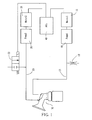
- an embodiment of the present invention is configured as shown in FIG. 1 and includes a first vacuum source 10, a second vacuum source 20, a throttle hole 12, a solenoid relief valve 22, a first tube 13, a second tube 23, a breast shield 30, and a control circuit board 40.
- the first vacuum source 10 is driven by a first vacuum source motor 11 and is connected to the breast shield 30 via the first tube 13.
- the first tube 13 is provided with the throttle hole 12 to communicate with the atmosphere.
- the second vacuum source 20 is driven by a second vacuum source motor 21 and is connected to the breast shield 30 via the second tube 23.
- the second tube 23 is provided with the solenoid relief valve 22 to communicate with the atmosphere.
- the solenoid relief valve 22 When the solenoid relief valve 22 is activated, the second tube 23 is in communication with the atmosphere to rapidly remove negative pressure from the second tube 23 and from the breast shield 30.
- the first vacuum source motor 11, the second vacuum source motor 21, and the solenoid relief valve 22 are controlled by the control circuit board 40.
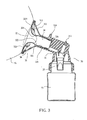
- the breast shield 30 is composed of a shield body 31, a liner 32, and a milk collecting container 33.
- the shield body 31 has a front end formed as a funnel-shaped breast receiving portion 311 for receiving a breast 01.
- the liner 32 is a soft resilient member provided between the inner side 312 of the breast receiving portion 311 and the breast 01 received in the breast receiving portion 311.
- the bottom end 326 of the liner 32 is provided with a gasket fitted tightly in the shield body 31 such that a second air chamber 35 is formed between the outer side 321 of the liner 32 and the inner side 312 of the breast receiving portion 311.
- the inner side 322 of the liner 32 is to be in contact with the breast 01 so that a first air chamber 34 is formed between the inner side 322 of the liner 32 and the breast 01.
- the shield body 31 is further provided with a first channel 313 and a second channel 314.
- the first channel 313 connects the first air chamber 34 and the milk collecting container 33 and is connected to the first vacuum source 10 via the first tube 13.
- the second channel 314 connects the second vacuum source 20 and the second air chamber 35 via the second tube 23.
- a check valve 37 is optionally provided between the first channel 313 and the milk collecting container 33. By doing so, the space in which the first vacuum source 10 is required to create negative pressure is effectively reduced without affecting the flow of the expressed milk into the milk collecting container 33.
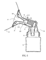
- the liner 32 which is to be in direct contact with the breast 01, includes three sections: a breast cushion section 323, a lip simulating section 324, and a tongue simulating section 325.
- the breast cushion section 323 is the funnel-shaped portion at the front end of the liner 32 and is provided with a cushion cylinder 3231. With the liner 32 being a soft resilient member, the breast cushion section 323 can increase the comfort of the breast 01 when the breast 01 is in contact with the liner 32.
- the lip simulating section 324 is the stem of the funnel-shaped portion of the liner 32, and the tongue simulating section 325 is connected to the rear end of the lip simulating section 324. Referring to FIG.
- the lip simulating section 324 moves radially toward the breast receiving portion 311. Consequently, the inner size of the lip simulating section 324 increases to simulate expansion of the oral cavity.
- the lip simulating section 324 resumes its original size to simulate contraction of the oral cavity.
- the tongue simulating section 325 has a radially outwardly bulging shape.
- the tongue simulating section 325 As the tongue simulating section 325 is long enough to cover the nipple 011 completely, radial contraction of the tongue simulating section 325 causes the tongue simulating section 325 to first attach to the side 0111 of the nipple 011 and then encircle the front end 0112 of the nipple 011, thereby simulating the wavy movement of the tongue.
- an additional liner supporting frame 38 is optionally provided to secure the liner 32 in place and prevent the expressed milk from contamination which may otherwise occur if the portion of the liner 32 that is to be in contact with the expressed milk is inadvertently touched during installation of the liner 32.
- a baby's suckling action is the repetition of a continuous cycle of opening and closing of the mouth and swallowing.
- negative pressure in the first air chamber 34 and in the second air chamber 35 is controlled in the following sequence:
- the creation of negative pressure in the second air chamber 35 is prior to the creation of negative pressure in the first air chamber 34.
- the negative pressure in the first air chamber 34 must be built up faster than that in the second air chamber 35.
- pressure in order for the negative pressure in the second air chamber 35 to disappear prior to the lowering of the negative pressure in the first air chamber 34, pressure must release faster from the second air chamber 35 than from the first air chamber 34.
- the first vacuum source 10 must have a higher pumping flow rate and a lower relief flow rate than the second vacuum source 20.
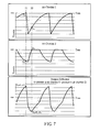
- the aforesaid variations of negative pressure in the air chambers are plotted against time in FIG. 7 , in which the variation of the pressure difference basically represents the movements of the lip simulating section 324 and of the tongue simulating section 325 of the liner 32.
- the pressure difference P dP is a positive value, meaning the negative pressure P 2P in the second air chamber 35 is greater (i.e., more negative) than the negative pressure P 1P in the first air chamber 34, and this is a simulation of the state in which the mouth is opened.
- the pressure difference P dN is a negative value, meaning the negative pressure P 2N in the second air chamber 35 is less (i.e., less negative) than the negative pressure P 1N in the first air chamber 34, and this is a simulation of the state in which the mouth is shut and swallowing begins.
- the first vacuum source 10 and the second vacuum source 20 must be vacuum pumps of different flow rates and be driven by different motors respectively.
- the flow rate of the first vacuum source 10 must be at least five times as high as that of the second vacuum source 20, wherein the ratio may vary slightly with the ratio of interior space between the first air chamber 34 and the second air chamber 35.
- the first vacuum source 10 must have a flow rate not lower than 9 L/min to provide an effective suckling frequency (i.e., 45 to 110 cycles/min).
- each cycle consists of stage 1, stage 2, and stage 3.
- the duration of each cycle is the sum of the durations of the three stages and determines the suckling frequency.
- the duration of stage 3 should take up 40% to 60% of the duration of an entire cycle.
- the duration of stage 2 should be between 0.08 and 0.25 second.
- Stage 1 2 3 Time sequence 0 s to 0.5 s 0.5 s to 0.6 s 0.6 s to 1.2 s First vacuum source motor (11) OFF ON OFF Second vacuum source motor (21) ON ON ON or OFF Solenoid relief valve (22) OFF OFF ON
- FIG. 8 which is hereinafter referred to as the second embodiment and includes a first vacuum source 10, a second vacuum source 20, a vacuum tank 14, a solenoid control valve 15, a throttle hole 12, a solenoid relief valve 22, a first tube 13, a second tube 23, an breast shield 30, and a control circuit board 40.
- the first vacuum source 10 is driven by a vacuum source motor 11A and is connected to the vacuum tank 14.
- the vacuum source motor 11A operates at all times (or substantially at all times) to provide the vacuum tank 14 with sufficient negative pressure.
- the other outlet of the vacuum tank 14 is provided with the solenoid control valve 15 and is connected to the first channel 313 in the breast shield 30 via the first tube 13.
- the first tube 13 is provided with the throttle hole 12 to communicate with the atmosphere.
- the solenoid control valve 15 When the solenoid control valve 15 is activated, the vacuum tank 14 is in communication with the first tube 13 such that negative pressure is rapidly created in the first tube 13 and in the first air chamber 34 in the breast shield 30.
- the vacuum tank 14 is blocked from the first tube 13, and the negative pressure in the first tube 13 and in the first air chamber 34 in the breast shield 30 disappears slowly through the throttle hole 12.
- the second vacuum source 20 is also driven by the vacuum source motor 11A and is connected to the second channel 314 in the breast shield 30 via the second tube 23.
- the second tube 23 is provided with the solenoid relief valve 22 to communicate with the atmosphere.
- the solenoid relief valve 22 is activated, the second tube 23 is in communication with the atmosphere to rapidly remove negative pressure from the second tube 23 and from the second air chamber 35.
- the vacuum source motor 11A, the solenoid control valve 15, and the solenoid relief valve 22 are controlled by the control circuit board 40.
- the two vacuum sources in the second embodiment are vacuum pumps of the same specifications, are driven by a single motor, and can be implemented by low flow-rate vacuum pumps (e.g., with a flow rate ⁇ 3 L/min). Therefore, the volume and cost of the resultant milk expressing device can be substantially reduced as compared with those in the first embodiment.
- the combination of the two vacuum pumps and the single motor in the second embodiment may also be replaced by two independent vacuum pumps, as in the less preferred embodiment shown in FIG. 9 .
- This embodiment hereinafter referred to as the third embodiment, includes a first vacuum source 10, a second vacuum source 20, a vacuum tank 14, a solenoid control valve 15, a throttle hole 12, a solenoid relief valve 22, a first tube 13, a second tube 23, a breast shield 30, and a control circuit board 40.
- the first vacuum source 10 is driven by a first vacuum source motor 11 and is connected to the vacuum tank 14.
- the first vacuum source motor 11 operates at all times (or substantially at all times) to provide the vacuum tank 14 with sufficient negative pressure.
- the other outlet of the vacuum tank 14 is provided with the solenoid control valve 15 and is connected to the first channel 313 in the breast shield 30 via the first tube 13.
- the first tube 13 is provided with the throttle hole 12 to communicate with the atmosphere.
- the solenoid control valve 15 When the solenoid control valve 15 is activated, the vacuum tank 14 is in communication with the first tube 13 such that negative pressure is rapidly created in the first tube 13 and in the first air chamber 34 in the breast shield 30.
- the solenoid control valve 15 is turned off, the vacuum tank 14 is blocked from the first tube 13, and the negative pressure in the first tube 13 and in the first air chamber 34 in the breast shield 30 disappears slowly through the throttle hole 12.
- the second vacuum source 20 is driven by a second vacuum source motor 21 and is connected to the second channel 314 in the breast shield 30 via the second tube 23.
- the second tube 23 is provided with the solenoid relief valve 22 to communicate with the atmosphere.
- the solenoid relief valve 22 When the solenoid relief valve 22 is activated, the second tube 23 is in communication with the atmosphere to rapidly remove negative pressure from the second tube 23 and from the second air chamber 35 in the breast shield 30.
- the first vacuum source motor 11, the second vacuum source motor 21, the solenoid control valve 15, and the solenoid relief valve 22 are controlled by the control circuit board 40.
- the third embodiment has the same effect as the previous two embodiments.
- the two vacuum sources in the third embodiment can be implemented by low flow-rate vacuum pumps (e.g., with flow rates ⁇ 3 L/min)
- the cost and physical volume of the resultant milk expressing device can be reduced as compared with those in the first embodiment, though slightly increased as compared with those in the second embodiment.
- the first vacuum source 10 and the second vacuum source 20 in the third embodiment are driven by their respective motors, the two vacuum sources are not linked in terms of control, and this allows more flexible and more accurate control over the movements of the various parts of the liner 32 than in the second embodiment, in which the two vacuum sources are driven by a single motor.
- first vacuum source 10 and the second vacuum source 20 are independently driven by their respective motors allows the movements of the various parts of the liner 32 to be more flexibly and more accurately controlled.
- a negative pressure sensor 60 can be provided on the first tube 13, and a negative pressure sensor 61, on the second tube 23.
- Each pressure sensor produces sensing signals according to pressure level of corresponding tube and chamber. The sensing signals will be sent to the control circuit board 40, so as for the control circuit board 40 to more accurately control the movement of each part of the liner 32 according to the sensing signals.
Landscapes
- Health & Medical Sciences (AREA)
- Heart & Thoracic Surgery (AREA)
- Biomedical Technology (AREA)
- Vascular Medicine (AREA)
- Engineering & Computer Science (AREA)
- Anesthesiology (AREA)
- Pediatric Medicine (AREA)
- Hematology (AREA)
- Life Sciences & Earth Sciences (AREA)
- Animal Behavior & Ethology (AREA)
- General Health & Medical Sciences (AREA)
- Public Health (AREA)
- Veterinary Medicine (AREA)
- External Artificial Organs (AREA)
Priority Applications (1)
| Application Number | Priority Date | Filing Date | Title |
|---|---|---|---|
| EP12005321.0A EP2687246A1 (de) | 2012-07-20 | 2012-07-20 | Milchausdrückvorrichtung, die zum Simulieren des Saugens eines Babys in der Lage ist |
Applications Claiming Priority (1)
| Application Number | Priority Date | Filing Date | Title |
|---|---|---|---|
| EP12005321.0A EP2687246A1 (de) | 2012-07-20 | 2012-07-20 | Milchausdrückvorrichtung, die zum Simulieren des Saugens eines Babys in der Lage ist |
Publications (1)
| Publication Number | Publication Date |
|---|---|
| EP2687246A1 true EP2687246A1 (de) | 2014-01-22 |
Family
ID=46651315
Family Applications (1)
| Application Number | Title | Priority Date | Filing Date |
|---|---|---|---|
| EP12005321.0A Withdrawn EP2687246A1 (de) | 2012-07-20 | 2012-07-20 | Milchausdrückvorrichtung, die zum Simulieren des Saugens eines Babys in der Lage ist |
Country Status (1)
| Country | Link |
|---|---|
| EP (1) | EP2687246A1 (de) |
Cited By (9)
| Publication number | Priority date | Publication date | Assignee | Title |
|---|---|---|---|---|
| WO2015185342A1 (en) * | 2014-06-05 | 2015-12-10 | Koninklijke Philips N.V. | Breast pump |
| CN107568070A (zh) * | 2017-10-19 | 2018-01-12 | 东阿阿胶股份有限公司 | 一种驴用挤奶器 |
| WO2018115234A1 (en) | 2016-12-23 | 2018-06-28 | Koninklijke Philips N.V. | Funnel for a breast pump, breast pump and method for operation of a breast pump |
| WO2019205040A1 (zh) * | 2018-04-26 | 2019-10-31 | 广东好女人母婴用品股份有限公司 | 一种用于乳房的双边负压调节装置 |
| CN111135358A (zh) * | 2020-01-19 | 2020-05-12 | 无锡新中瑞婴儿用品有限公司 | 吸奶器及基于吸奶器的促进泌乳的工作方法 |
| CN112243385A (zh) * | 2018-06-08 | 2021-01-19 | 贝亲株式会社 | 电动吸奶器、电动吸奶器的控制方法及电动吸奶器的控制程序 |
| WO2021165892A1 (en) * | 2020-02-21 | 2021-08-26 | Medela Holding Ag | Breastpump unit and method of operation |
| WO2022106252A1 (en) * | 2020-11-17 | 2022-05-27 | Koninklijke Philips N.V. | Breast shield for a breast pump |
| JP2022533829A (ja) * | 2019-05-17 | 2022-07-26 | レズメド コーポレーション | スマート接続された乳房ポンプ |
Citations (7)
| Publication number | Priority date | Publication date | Assignee | Title |
|---|---|---|---|---|
| US20020198489A1 (en) * | 2001-06-22 | 2002-12-26 | Silver Brian H. | Breastshield with multi-pressure and expansible chamber construction, related breastpump and method |
| US6706012B2 (en) | 2000-06-12 | 2004-03-16 | L. Jason Clute | Apparatus for expressing milk |
| EP1593402A1 (de) * | 2004-05-06 | 2005-11-09 | Clute, Lorne Jason | Auspresssatz und Trichtereinsatz für Brustpumpvorrichtungen |
| US7396340B2 (en) | 2004-03-30 | 2008-07-08 | Pigeon Corporation | Breast pump |
| WO2010054174A1 (en) * | 2008-11-07 | 2010-05-14 | Simplisse, Inc. | Breast pump |
| WO2010083485A2 (en) * | 2009-01-16 | 2010-07-22 | Learning Curve Brands, Inc. | Breast pump and method of use |
| US20110071466A1 (en) * | 2009-09-22 | 2011-03-24 | Medela Holding Ag | Highly efficient breastpump and system for expressing breastmilk |
-
2012
- 2012-07-20 EP EP12005321.0A patent/EP2687246A1/de not_active Withdrawn
Patent Citations (7)
| Publication number | Priority date | Publication date | Assignee | Title |
|---|---|---|---|---|
| US6706012B2 (en) | 2000-06-12 | 2004-03-16 | L. Jason Clute | Apparatus for expressing milk |
| US20020198489A1 (en) * | 2001-06-22 | 2002-12-26 | Silver Brian H. | Breastshield with multi-pressure and expansible chamber construction, related breastpump and method |
| US7396340B2 (en) | 2004-03-30 | 2008-07-08 | Pigeon Corporation | Breast pump |
| EP1593402A1 (de) * | 2004-05-06 | 2005-11-09 | Clute, Lorne Jason | Auspresssatz und Trichtereinsatz für Brustpumpvorrichtungen |
| WO2010054174A1 (en) * | 2008-11-07 | 2010-05-14 | Simplisse, Inc. | Breast pump |
| WO2010083485A2 (en) * | 2009-01-16 | 2010-07-22 | Learning Curve Brands, Inc. | Breast pump and method of use |
| US20110071466A1 (en) * | 2009-09-22 | 2011-03-24 | Medela Holding Ag | Highly efficient breastpump and system for expressing breastmilk |
Cited By (18)
| Publication number | Priority date | Publication date | Assignee | Title |
|---|---|---|---|---|
| WO2015185342A1 (en) * | 2014-06-05 | 2015-12-10 | Koninklijke Philips N.V. | Breast pump |
| CN105169503A (zh) * | 2014-06-05 | 2015-12-23 | 皇家飞利浦有限公司 | 吸奶器 |
| RU2691003C2 (ru) * | 2014-06-05 | 2019-06-07 | Конинклейке Филипс Н.В. | Молокоотсос |
| CN105169503B (zh) * | 2014-06-05 | 2019-09-03 | 皇家飞利浦有限公司 | 吸奶器 |
| US10568996B2 (en) | 2014-06-05 | 2020-02-25 | Koninklijke Philips N.V. | Breast pump |
| WO2018115234A1 (en) | 2016-12-23 | 2018-06-28 | Koninklijke Philips N.V. | Funnel for a breast pump, breast pump and method for operation of a breast pump |
| CN107568070A (zh) * | 2017-10-19 | 2018-01-12 | 东阿阿胶股份有限公司 | 一种驴用挤奶器 |
| WO2019205040A1 (zh) * | 2018-04-26 | 2019-10-31 | 广东好女人母婴用品股份有限公司 | 一种用于乳房的双边负压调节装置 |
| CN112243385B (zh) * | 2018-06-08 | 2023-09-22 | 贝亲株式会社 | 电动吸奶器、电动吸奶器的控制方法及电动吸奶器的控制程序 |
| CN112243385A (zh) * | 2018-06-08 | 2021-01-19 | 贝亲株式会社 | 电动吸奶器、电动吸奶器的控制方法及电动吸奶器的控制程序 |
| JP2022533829A (ja) * | 2019-05-17 | 2022-07-26 | レズメド コーポレーション | スマート接続された乳房ポンプ |
| CN111135358A (zh) * | 2020-01-19 | 2020-05-12 | 无锡新中瑞婴儿用品有限公司 | 吸奶器及基于吸奶器的促进泌乳的工作方法 |
| WO2021165892A1 (en) * | 2020-02-21 | 2021-08-26 | Medela Holding Ag | Breastpump unit and method of operation |
| CN115243734A (zh) * | 2020-02-21 | 2022-10-25 | 美德乐控股公司 | 吸乳泵单元和操作方法 |
| JP2023514409A (ja) * | 2020-02-21 | 2023-04-05 | メデラ ホールディング アーゲー | 搾乳器ユニットおよび操作方法 |
| CN115243734B (zh) * | 2020-02-21 | 2025-09-30 | 美德乐控股公司 | 吸乳泵单元和操作方法 |
| AU2021223172B2 (en) * | 2020-02-21 | 2025-12-18 | Medela Holding Ag | Breastpump unit and method of operation |
| WO2022106252A1 (en) * | 2020-11-17 | 2022-05-27 | Koninklijke Philips N.V. | Breast shield for a breast pump |
Similar Documents
| Publication | Publication Date | Title |
|---|---|---|
| US8961454B2 (en) | Milk expressing device capable of simulating a baby's suckling | |
| EP2687246A1 (de) | Milchausdrückvorrichtung, die zum Simulieren des Saugens eines Babys in der Lage ist | |
| EP4247448B1 (de) | Brustschutz für eine brustpumpe | |
| CN1247269C (zh) | 催乳杯及其制造和使用方法 | |
| JP3514467B2 (ja) | 人間の乳房に使用する搾乳器 | |
| CN110997030B (zh) | 母乳泵 | |
| CN102209516B (zh) | 用于非营养性吮吸诱导脉冲发生器的方法和装置 | |
| CN217593463U (zh) | 汲乳器 | |
| EP0198469B1 (de) | Transportierbare elektrisch betriebene Einrichtung zum Absaugen von Muttermilch | |
| TW202327668A (zh) | 汲乳器 | |
| CN116421846A (zh) | 刺激哺乳者的乳腺喷射乳液的汲乳方法 | |
| CN103751863B (zh) | 颌骨囊性病变开窗引流负压阻塞装置 | |
| CN102657902A (zh) | 一种模拟婴儿吸乳方式的集乳装置 | |
| CN203829372U (zh) | 颌骨囊性病变开窗引流负压阻塞装置 | |
| TWM445988U (zh) | 一種模擬嬰兒吸乳方式的集乳裝置 | |
| US20250049996A1 (en) | A breast pump | |
| CN219681295U (zh) | 吸乳泵 | |
| CN219764105U (zh) | 吸乳泵 | |
| CN222150621U (zh) | 乳汁挤取装置 | |
| EP4197567A1 (de) | Milchpumpe | |
| CN209678101U (zh) | 婴童吸管 | |
| KR20250000638U (ko) | 돌기를 포함하는 모유 흡입기 | |
| JP2018033695A (ja) | 搾乳装置及び搾乳装置の制御方法 | |
| WO2025207797A1 (en) | Compact wearable massage and suction system |
Legal Events
| Date | Code | Title | Description |
|---|---|---|---|
| PUAI | Public reference made under article 153(3) epc to a published international application that has entered the european phase |
Free format text: ORIGINAL CODE: 0009012 |
|
| AK | Designated contracting states |
Kind code of ref document: A1 Designated state(s): AL AT BE BG CH CY CZ DE DK EE ES FI FR GB GR HR HU IE IS IT LI LT LU LV MC MK MT NL NO PL PT RO RS SE SI SK SM TR |
|
| AX | Request for extension of the european patent |
Extension state: BA ME |
|
| STAA | Information on the status of an ep patent application or granted ep patent |
Free format text: STATUS: THE APPLICATION IS DEEMED TO BE WITHDRAWN |
|
| 18D | Application deemed to be withdrawn |
Effective date: 20140723 |