EP2687308A2 - Drehmaschine zum Bearbeiten gekrümmter Oberflächen - Google Patents
Drehmaschine zum Bearbeiten gekrümmter Oberflächen Download PDFInfo
- Publication number
- EP2687308A2 EP2687308A2 EP13177137.0A EP13177137A EP2687308A2 EP 2687308 A2 EP2687308 A2 EP 2687308A2 EP 13177137 A EP13177137 A EP 13177137A EP 2687308 A2 EP2687308 A2 EP 2687308A2
- Authority
- EP
- European Patent Office
- Prior art keywords
- sliding
- lathe
- cross beam
- slidably
- pair
- Prior art date
- Legal status (The legal status is an assumption and is not a legal conclusion. Google has not performed a legal analysis and makes no representation as to the accuracy of the status listed.)
- Granted
Links
Images



Classifications
-
- B—PERFORMING OPERATIONS; TRANSPORTING
- B23—MACHINE TOOLS; METAL-WORKING NOT OTHERWISE PROVIDED FOR
- B23B—TURNING; BORING
- B23B3/00—General-purpose turning-machines or devices, e.g. centre lathes with feed rod and lead screw; Sets of turning-machines
- B23B3/06—Turning-machines or devices characterised only by the special arrangement of constructional units
-
- B—PERFORMING OPERATIONS; TRANSPORTING
- B23—MACHINE TOOLS; METAL-WORKING NOT OTHERWISE PROVIDED FOR
- B23B—TURNING; BORING
- B23B5/00—Turning-machines or devices specially adapted for particular work; Accessories specially adapted therefor
- B23B5/36—Turning-machines or devices specially adapted for particular work; Accessories specially adapted therefor for turning specially-shaped surfaces by making use of relative movement of the tool and work produced by geometrical mechanisms, i.e. forming-lathes
-
- B—PERFORMING OPERATIONS; TRANSPORTING
- B23—MACHINE TOOLS; METAL-WORKING NOT OTHERWISE PROVIDED FOR
- B23Q—DETAILS, COMPONENTS, OR ACCESSORIES FOR MACHINE TOOLS, e.g. ARRANGEMENTS FOR COPYING OR CONTROLLING; MACHINE TOOLS IN GENERAL CHARACTERISED BY THE CONSTRUCTION OF PARTICULAR DETAILS OR COMPONENTS; COMBINATIONS OR ASSOCIATIONS OF METAL-WORKING MACHINES, NOT DIRECTED TO A PARTICULAR RESULT
- B23Q1/00—Members which are comprised in the general build-up of a form of machine, particularly relatively large fixed members
- B23Q1/01—Frames, beds, pillars or like members; Arrangement of ways
- B23Q1/012—Portals
-
- B—PERFORMING OPERATIONS; TRANSPORTING
- B23—MACHINE TOOLS; METAL-WORKING NOT OTHERWISE PROVIDED FOR
- B23Q—DETAILS, COMPONENTS, OR ACCESSORIES FOR MACHINE TOOLS, e.g. ARRANGEMENTS FOR COPYING OR CONTROLLING; MACHINE TOOLS IN GENERAL CHARACTERISED BY THE CONSTRUCTION OF PARTICULAR DETAILS OR COMPONENTS; COMBINATIONS OR ASSOCIATIONS OF METAL-WORKING MACHINES, NOT DIRECTED TO A PARTICULAR RESULT
- B23Q2230/00—Special operations in a machine tool
- B23Q2230/004—Using a cutting tool reciprocating at high speeds, e.g. "fast tool"
Definitions
- the present disclosure generally relates to lathes, and particularly, to a lathe which can machine a curved surface.
- a milling cutter with different cutting edges is used for machining curved surfaces. Some tracks are formed on the milled surface of the workpiece because of intermitted contact and interrupted milling by the milling cutter. A polish step needs to be added for a better appearance.
- a lathe is used for machining curved surfaces, only a two dimensional curved surface with rotary feature can be machined because the movement of a cutter of the lathe is limited.
- a lathe includes a machine support, a working table positioned on the machine support, a rotating driver, a moving device, and a feeding device.
- the rotating driver rotates the work table.
- the moving device includes at least one cross beam, at least one first driving mechanism, and at least one second driving mechanism.
- the cross beam is movably positioned on the machine support above the working table.
- the feeding device is movably positioned on the at least one cross beam, and includes a feeding driving mechanism and a cutter.
- the first driving mechanism drives the cross beam to move along a first direction
- the second driving mechanism drives the feeding device to move along a second direction at about ninety degrees from the first direction.
- the feeding mechanism drives the cutter to move backwards and forwards along a third direction perpendicular to the first and second direction.
- FIG. 1 is an isometric view of an embodiment of a lathe having a feeding device and a work table.
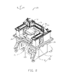
- FIG. 2 is a partial, isometric view of the lathe of FIG. 1 .
- FIG. 3 shows an exploded and isometric view of the lathe of FIG. 2
- FIG. 4 shows an isometric view of the feeding device and the work table of the lathe of FIG. 1 .
- FIG. 5 is an exploded, isometric view of the feeding device of FIG. 1 .
- FIG. 6 is similar to FIG. 5 , but viewed from another aspect.
- FIGS. 1 and 2 show an embodiment of a lathe 100.
- the lathe 100 includes a machine support 10, a work table 20, a moving device 30, a feeding device 40, and a controller (not shown).
- the work table 20 holds a workpiece in place and is supported by the machine support 10.
- the moving device 30 is movably positioned on the machine support 10 above the work table 20.
- the feeding device 40 is slidably mounted on the moving device 30.
- the controller is electrically connected with the work table 20, the moving device 30, and the feeding device 40 for controlling the lathe 100. Under the control of the controller, the moving device 30 can be driven to move with the feeding device 40, such that the feeding device 40 can be driven to move along the X, the Y, and the Z axes.
- the machine support 10 includes a base 11 and a pair of support bodies 13 positioned substantially parallel on the base 11.
- a pair of first sliding rails 131 are positioned substantially parallel on a surface of each support body 13 away from the base 11, and arranged apart from each other.
- the first sliding rails 131 extend substantially parallel to the X-axis (a first direction).
- a receiving groove 133 is formed on each support body 13 between the two first sliding rails 131.
- the work table 20 is substantially cylindrical, and rotatably positioned on the base 11 between the two support bodies 13 via the rotating driver 21.
- the rotating driver 21 drives the work table 20 and a workpiece placed on the work table 20 to rotate.
- the rotating driver 21 is a direct drive motor.
- the moving device 30 is slidably mounted on the pair of support bodies 13 above the work table 20.
- the moving device 30 includes two cross beams 31, four sliding bases 33, four first driving mechanisms 35, and two second driving mechanisms 37.
- the two cross beams 31 are positioned spaced apart on the support bodies 13 for high stability. Opposite ends of each cross beam 31 are slidably positioned on the support bodies 13 via a pair of sliding bases 33, respectively.
- the extending direction of the cross beam 31 is substantially parallel to the Y-axis (a second direction).
- a pair of second sliding rails 311 is positioned on a side surface of each cross beam 31 and extending substantially parallel to the Y-axis.
- Two side surfaces having the second sliding rails 311 of the cross beams 31 are positioned face to face.
- Two sliding bases 33 are installed on the opposite ends of the corresponding cross beam 31 to slidably connect with the first sliding rails 131.
- the sliding base 33 includes a first sliding block 331 slidably engaging with the first sliding rails 131.
- Each first driving mechanism 35 is mounted on a surface of one sliding base 33 away from the cross beam 31 and received in one receiving groove 133.
- the first driving mechanisms 35 are configured to drive the cross beams 31 to move along the first sliding rails 131.
- Each of the first driving mechanisms 35 includes a first forcer 351 and a first stator 353.
- the first forcer 351 is fixedly mounted on the sliding base 31 facing the receiving groove 133.
- Two first stators 353 are fixedly received in each of the receiving grooves 133.
- One second driving mechanism 37 is mounted on each of the cross beams 31 between two second sliding rails 311 to drive the feeding device 40 to move along the second sliding rails 311.
- Each of the second driving mechanisms 37 includes a second forcer 371 and a second stator 373.
- Each of the second forcers 371 are fixedly mounted on each of the opposite surfaces of the feeding device 40 facing the cross beams 31.
- Both of the second stators 373 are installed on each of the cross beams 31 between two second sliding rails 311.
- the first driving mechanisms 35 and the second driving mechanism 37 are electrically connected to the controller.
- the first driving mechanisms 35 and the second driving mechanism 37 are linear motors.
- the first driving mechanisms 35 and the second driving mechanism 37 are other drivers, such as hydraulic cylinders or rams.
- the number of the first driving mechanisms 35, the second driving mechanism 37, and the cross beam 31 can be designed according to their applications.
- FIGS. 3 to 5 shows that the feeding device 40 is slidably positioned between the two cross beams 31.
- the feeding device 40 includes a sliding saddle 41, a mounting seat 43, a tool holder 45, a feeding mechanism 47, and a cutter 49.
- the sliding saddle 41 is movably assembled with the cross beams 31.
- the mounting seat 43 is slidably connected to the sliding saddle 41 away from the cross beam 31.
- the feeding mechanisms 47 are mounted and received in the mounting seat 43 to electrically connect with the controller.
- the tool holder 45 is slidably positioned on the mounting seat 43, and has a reciprocating motion substantially parallel to the Z-axis (the Z-axis direction, a second direction) relative to the mounting seat 43.
- the sliding saddle 41 is slidably positioned between the two cross beams 31.
- Two second sliding blocks 411 are separately positioned on opposite surfaces of the sliding saddle 41 away from the tool holder 45, and substantially parallel to the Y-axis towards the cross beam 31.
- the second sliding blocks 411 are slidably engaged with the correspondingly second sliding rails 311.
- Each of the second forcers 371 is positioned between the two second sliding blocks 411.
- the mounting seat 43 includes a frame 431 and two mounting boards 433.
- the frame 431 includes a first side wall 4311 and a second side wall 4313.
- the first side wall 4311 and the second side wall 4313 are positioned substantially parallel to each other and cooperatively define a receiving space 4315.
- the fist side wall 4311 is slidably connected with the sliding saddle 41.
- Two guiding portions 4317 protrude from an inner surface of the first side wall 4311 facing toward the second side wall 4315 and extend substantially parallel to the Z-axis.
- a through groove 4318 is defined in the second side wall 4313 and extends along a direction substantially parallel to the Z-axis corresponding to the guiding portions 4317.
- Two guiding portions 4319 protrude from an outer surface of the second side wall 4313 at two sides of the through groove 4318.
- the guiding portions 4319 are sliding rails
- the frame 431 is integrally formed.
- Two mounting boards 433 are respectively installed on two opening sides of the frame 431. Each mounting board 433 is connected substantially perpendicularly to the first wall 4311 and the second side wall 4313 to close the two opening sides of the frame 431.
- the tool holder 45 slidably connects with the mounting seat 43.
- the tool holder 45 is substantially "T" shaped, and includes a main body 451 and a sliding board 453 protruding substantially perpendicularly from the main body 451.
- the main body 451 is a bar of material tapering in at both ends, and positioned outside of the mounting seat 43.
- Two distanced holding portions 4511 are positioned on a bottom of the main body 451 away from the sliding board 453.
- Four first direct portions 4513 are positioned on a surface of the main body 451 adjacent to the sliding board 453.
- the four first direct portions 4513 are divided into two groups, each group having two first direct portions 4513 slidably engaging with one guiding portion 4319.
- the sliding board 453 is located between the two groups of the first direct portions 4513.
- the sliding board 453 passes through the through groove 4318 and is slidably attached to the two guiding portions 4317, dividing the receiving space 4315 into two parts.
- a second direct portion 4531 is formed on an end of the sliding board 453 away from the main body 451, and received in the guiding portion 4317.
- the first direct portions 4513 are sliding blocks
- the second direct portion 4531 is a sliding rail.
- the feeding mechanism 47 is mounted in the mounting seat 43, and includes two drivers 471.
- the two drivers 471 are received in the receiving space 4315 and positioned on two sides of the sliding board 453, respectively.
- the drivers 471 are linear motors.
- Each driver 471 includes a forcer 4711 and a stator 4713.
- Each forcer 4711 is fixed to a surface of each of the mounting boards 433.
- the sliding board 453 is positioned between the two forcers 4711.
- the forcers 4711 produce alternating magnetic fields when the forcers 4711 are supplied with an alternating electrical current.
- Two stators 4713 are respectively attached on the opposite surfaces of the sliding board 453.
- Each stator 4713 is located between a forcer 4711 and the sliding board 453.
- the number of drivers 471 can be designed according to application.
- the two drivers 471 can replace a single driver with more power, or three or more drivers can be positioned to drive the tool holder 45 to maximize the available power, and simplify assembly of the drivers.
- the cutter 49 is clamped between the two holding portions 4511 for machining curved surfaces of the workpiece.
- the mounting seat 43 may be attached on the sliding saddle 41 when the lathe 100 machines the workpiece of one type. In other words, the mounting seat 43 does not need to move along the Z-axis direction.
- a driving mechanism electrically connected with the controller may be positioned in the feeding device 40 to drive the mounting seat 43 to slide along the sliding saddle 41 in the Z-axis.
- the sliding saddle 41 may be omitted, and the mounting seat 43 can be directly slidably positioned on the cross beam 31.
- the forcers 4711 may be directly installed on the frame 431.
- the alternating magnetic fields produced by the forcers 4711 drive the stators 4713, thereby causing the tool holder 45 to undergo a reciprocating motion at high speed along the guiding portions 4317.
- the work table 20 is positioned between the two support bodies 13.
- the cross beams 31 are installed on the two support bodies 13 via the sliding bases 33.
- the first driving mechanism 35 and the second mechanism 37 are mounted on the moving device 30 and elastically connected with the controller.
- the sliding saddle 41 is also positioned on the cross beam 31.
- the two stators 4713 are fixedly mounted on two surfaces of the sliding board 453.
- the sliding board 453 passes through the through groove 4318 and slidably connects with the second direct portion 4531.
- Each forcer 4711 is installed on one mounting board 433 and received in the mounting seat 43 together with the mounting board 433.
- the cutter 49 is fixedly mounted between the two holding portions 4511.
- the feeding device 40 is positioned on the sliding saddle 41 and electrically connected to the controller.
- the workpiece is placed on the work table 20.
- the feeding device 40 moves and arrives at a position above the workpiece.
- the first driving mechanism 35 drives the moving device 30 to move along the first sliding rails 131 in the X-axis direction, the rotating driver 21 drives the workpiece to rotate, and the cutter 49 is driven to move back and forth at high speed in the Z-axis direction by the drivers 471 for machining the workpiece.
- the rotating speed of the rotating driver 21, the speed and the range movement of the cutter 49 are programmed according to cutting required for each machining portion of the workpiece. A three dimensional curved surface will be machined because the cutting removal of the workpiece along the rotating direction in the Z-axis is different.
- the planar machining path of the cutter 49 is substantially spiral.
- the feeding device 40 and the work table 20 stop moving, and the moving device 30 returns to the initial position after completing the machining. The workpiece can then be unloaded from the work table 20.
- the feeding device 40 is capable of moving along X-axis and Y-axis via the moving device 30 and feeding with high speed in Z-axis for machining three dimensional curved surfaces. Compared with the conventional milling cutter machining, no other process needs to be performed on the workpiece used by the lathe 100 because the cutter 49 is continuously machining in three directions at one time. In addition, the work table 20 is directly driven to rotate by the rotating driver 21, such that the work table 20 is capable of adjustments with great torsion.
Landscapes
- Engineering & Computer Science (AREA)
- Mechanical Engineering (AREA)
- Turning (AREA)
Applications Claiming Priority (2)
| Application Number | Priority Date | Filing Date | Title |
|---|---|---|---|
| CN201210252845.0A CN103567461A (zh) | 2012-07-20 | 2012-07-20 | 车削设备 |
| CN201210252849.9A CN103567465B (zh) | 2012-07-20 | 2012-07-20 | 车削设备 |
Publications (3)
| Publication Number | Publication Date |
|---|---|
| EP2687308A2 true EP2687308A2 (de) | 2014-01-22 |
| EP2687308A3 EP2687308A3 (de) | 2015-02-11 |
| EP2687308B1 EP2687308B1 (de) | 2021-04-07 |
Family
ID=48795483
Family Applications (1)
| Application Number | Title | Priority Date | Filing Date |
|---|---|---|---|
| EP13177137.0A Active EP2687308B1 (de) | 2012-07-20 | 2013-07-18 | Drehmaschine zum Bearbeiten gekrümmter Oberflächen |
Country Status (1)
| Country | Link |
|---|---|
| EP (1) | EP2687308B1 (de) |
Cited By (2)
| Publication number | Priority date | Publication date | Assignee | Title |
|---|---|---|---|---|
| CN110052801A (zh) * | 2019-05-17 | 2019-07-26 | 深圳市东盈讯达电子有限公司 | 一种柔性单机组合线体的自动化多功能平台 |
| CN111037315A (zh) * | 2019-12-31 | 2020-04-21 | 枣庄北航机床创新研究院有限公司 | 一种立式加工机床 |
Family Cites Families (9)
| Publication number | Priority date | Publication date | Assignee | Title |
|---|---|---|---|---|
| DE19650360A1 (de) * | 1996-10-28 | 1998-05-07 | Wurst Karl Heinz Dr Ing | Antriebseinheit für eine Maschine |
| JPH10141468A (ja) * | 1996-11-11 | 1998-05-29 | Advantest Corp | 直線駆動装置用防油装置 |
| JP4094769B2 (ja) * | 1999-05-18 | 2008-06-04 | 日本トムソン株式会社 | 可動コイル型リニアモータを内蔵したスライド装置 |
| JP3610485B2 (ja) * | 1999-09-20 | 2005-01-12 | 株式会社日立製作所 | 数値制御曲面加工装置 |
| FR2820070B1 (fr) * | 2001-01-31 | 2003-04-25 | Jean Paul Coron | Corps profile monobloc destine a inclure un organe moteur et module lineaire realise a partir d'un tel corps |
| JP2004066430A (ja) * | 2002-08-08 | 2004-03-04 | O M Ltd | 複合工作機械 |
| US7357769B2 (en) * | 2005-05-25 | 2008-04-15 | Mori Seiki Co., Ltd. | Machine tool |
| CN201524905U (zh) * | 2009-02-09 | 2010-07-14 | 深圳市康铖机械设备有限公司 | 小型龙门双主轴钻铣数控机床 |
| DE102009058649A1 (de) * | 2009-12-16 | 2011-06-22 | Adams, Heinz, 66740 | Bohr-Fräsmaschine mit zusätzlichem Drehwerkzeug-Schlitten, Drehaufnahme, Drehwerkzeug und Drehtisch zum Drehen |
-
2013
- 2013-07-18 EP EP13177137.0A patent/EP2687308B1/de active Active
Non-Patent Citations (1)
| Title |
|---|
| None |
Cited By (2)
| Publication number | Priority date | Publication date | Assignee | Title |
|---|---|---|---|---|
| CN110052801A (zh) * | 2019-05-17 | 2019-07-26 | 深圳市东盈讯达电子有限公司 | 一种柔性单机组合线体的自动化多功能平台 |
| CN111037315A (zh) * | 2019-12-31 | 2020-04-21 | 枣庄北航机床创新研究院有限公司 | 一种立式加工机床 |
Also Published As
| Publication number | Publication date |
|---|---|
| EP2687308A3 (de) | 2015-02-11 |
| EP2687308B1 (de) | 2021-04-07 |
Similar Documents
| Publication | Publication Date | Title |
|---|---|---|
| US8881626B2 (en) | Lathe for machining curved surfaces | |
| US9381607B2 (en) | Feeding device and machine tool using the same | |
| US9409268B2 (en) | Machine tool with lathe tool and milling cutter | |
| EP2745959B1 (de) | Werkzeugmaschine mit Drehwerkzeug und Schabschneider | |
| US9254542B2 (en) | Machine tool with uninterrupted cutting | |
| US9550257B2 (en) | Method for machining metallic member using lathing and milling | |
| US9346143B2 (en) | Lathe for machining curved surfaces | |
| EP2745961B1 (de) | Verfahren zur Bearbeitung eines metallischen Bauteils durch Drehen und Fräsen | |
| US9718153B2 (en) | Method for machining metallic member using lathing and scraping | |
| US9259786B2 (en) | Method for machining curved surface using lathe | |
| EP2745960B1 (de) | Verfahren zur Bearbeitung eines metallischen Bauteils durch Drehen und Fräsen | |
| EP2687308B1 (de) | Drehmaschine zum Bearbeiten gekrümmter Oberflächen | |
| US9238306B2 (en) | Feeding device and machine tool using the same | |
| EP2687324B1 (de) | Zuführvorrichtung und Maschinenwerkzeug damit | |
| EP2745962B1 (de) | Verfahren zur Bearbeitung eines metallischen Bauteils durch Drehen und Schaben |
Legal Events
| Date | Code | Title | Description |
|---|---|---|---|
| PUAI | Public reference made under article 153(3) epc to a published international application that has entered the european phase |
Free format text: ORIGINAL CODE: 0009012 |
|
| AK | Designated contracting states |
Kind code of ref document: A2 Designated state(s): AL AT BE BG CH CY CZ DE DK EE ES FI FR GB GR HR HU IE IS IT LI LT LU LV MC MK MT NL NO PL PT RO RS SE SI SK SM TR |
|
| AX | Request for extension of the european patent |
Extension state: BA ME |
|
| PUAL | Search report despatched |
Free format text: ORIGINAL CODE: 0009013 |
|
| AK | Designated contracting states |
Kind code of ref document: A3 Designated state(s): AL AT BE BG CH CY CZ DE DK EE ES FI FR GB GR HR HU IE IS IT LI LT LU LV MC MK MT NL NO PL PT RO RS SE SI SK SM TR |
|
| AX | Request for extension of the european patent |
Extension state: BA ME |
|
| RIC1 | Information provided on ipc code assigned before grant |
Ipc: B23Q 1/01 20060101ALI20150105BHEP Ipc: B23B 3/06 20060101AFI20150105BHEP |
|
| 17P | Request for examination filed |
Effective date: 20150811 |
|
| RBV | Designated contracting states (corrected) |
Designated state(s): AL AT BE BG CH CY CZ DE DK EE ES FI FR GB GR HR HU IE IS IT LI LT LU LV MC MK MT NL NO PL PT RO RS SE SI SK SM TR |
|
| STAA | Information on the status of an ep patent application or granted ep patent |
Free format text: STATUS: EXAMINATION IS IN PROGRESS |
|
| 17Q | First examination report despatched |
Effective date: 20190408 |
|
| GRAP | Despatch of communication of intention to grant a patent |
Free format text: ORIGINAL CODE: EPIDOSNIGR1 |
|
| STAA | Information on the status of an ep patent application or granted ep patent |
Free format text: STATUS: GRANT OF PATENT IS INTENDED |
|
| INTG | Intention to grant announced |
Effective date: 20201203 |
|
| RAP1 | Party data changed (applicant data changed or rights of an application transferred) |
Owner name: FUXIANG PRECISION INDUSTRIAL (KUNSHAN) CO., LTD. |
|
| GRAS | Grant fee paid |
Free format text: ORIGINAL CODE: EPIDOSNIGR3 |
|
| GRAA | (expected) grant |
Free format text: ORIGINAL CODE: 0009210 |
|
| STAA | Information on the status of an ep patent application or granted ep patent |
Free format text: STATUS: THE PATENT HAS BEEN GRANTED |
|
| AK | Designated contracting states |
Kind code of ref document: B1 Designated state(s): AL AT BE BG CH CY CZ DE DK EE ES FI FR GB GR HR HU IE IS IT LI LT LU LV MC MK MT NL NO PL PT RO RS SE SI SK SM TR |
|
| REG | Reference to a national code |
Ref country code: GB Ref legal event code: FG4D |
|
| REG | Reference to a national code |
Ref country code: AT Ref legal event code: REF Ref document number: 1379032 Country of ref document: AT Kind code of ref document: T Effective date: 20210415 Ref country code: CH Ref legal event code: EP |
|
| REG | Reference to a national code |
Ref country code: DE Ref legal event code: R096 Ref document number: 602013076702 Country of ref document: DE |
|
| REG | Reference to a national code |
Ref country code: IE Ref legal event code: FG4D |
|
| REG | Reference to a national code |
Ref country code: LT Ref legal event code: MG9D |
|
| REG | Reference to a national code |
Ref country code: NL Ref legal event code: MP Effective date: 20210407 Ref country code: AT Ref legal event code: MK05 Ref document number: 1379032 Country of ref document: AT Kind code of ref document: T Effective date: 20210407 |
|
| PG25 | Lapsed in a contracting state [announced via postgrant information from national office to epo] |
Ref country code: AT Free format text: LAPSE BECAUSE OF FAILURE TO SUBMIT A TRANSLATION OF THE DESCRIPTION OR TO PAY THE FEE WITHIN THE PRESCRIBED TIME-LIMIT Effective date: 20210407 Ref country code: BG Free format text: LAPSE BECAUSE OF FAILURE TO SUBMIT A TRANSLATION OF THE DESCRIPTION OR TO PAY THE FEE WITHIN THE PRESCRIBED TIME-LIMIT Effective date: 20210707 Ref country code: HR Free format text: LAPSE BECAUSE OF FAILURE TO SUBMIT A TRANSLATION OF THE DESCRIPTION OR TO PAY THE FEE WITHIN THE PRESCRIBED TIME-LIMIT Effective date: 20210407 Ref country code: NL Free format text: LAPSE BECAUSE OF FAILURE TO SUBMIT A TRANSLATION OF THE DESCRIPTION OR TO PAY THE FEE WITHIN THE PRESCRIBED TIME-LIMIT Effective date: 20210407 Ref country code: LT Free format text: LAPSE BECAUSE OF FAILURE TO SUBMIT A TRANSLATION OF THE DESCRIPTION OR TO PAY THE FEE WITHIN THE PRESCRIBED TIME-LIMIT Effective date: 20210407 Ref country code: FI Free format text: LAPSE BECAUSE OF FAILURE TO SUBMIT A TRANSLATION OF THE DESCRIPTION OR TO PAY THE FEE WITHIN THE PRESCRIBED TIME-LIMIT Effective date: 20210407 |
|
| PG25 | Lapsed in a contracting state [announced via postgrant information from national office to epo] |
Ref country code: GR Free format text: LAPSE BECAUSE OF FAILURE TO SUBMIT A TRANSLATION OF THE DESCRIPTION OR TO PAY THE FEE WITHIN THE PRESCRIBED TIME-LIMIT Effective date: 20210708 Ref country code: LV Free format text: LAPSE BECAUSE OF FAILURE TO SUBMIT A TRANSLATION OF THE DESCRIPTION OR TO PAY THE FEE WITHIN THE PRESCRIBED TIME-LIMIT Effective date: 20210407 Ref country code: IS Free format text: LAPSE BECAUSE OF FAILURE TO SUBMIT A TRANSLATION OF THE DESCRIPTION OR TO PAY THE FEE WITHIN THE PRESCRIBED TIME-LIMIT Effective date: 20210807 Ref country code: RS Free format text: LAPSE BECAUSE OF FAILURE TO SUBMIT A TRANSLATION OF THE DESCRIPTION OR TO PAY THE FEE WITHIN THE PRESCRIBED TIME-LIMIT Effective date: 20210407 Ref country code: SE Free format text: LAPSE BECAUSE OF FAILURE TO SUBMIT A TRANSLATION OF THE DESCRIPTION OR TO PAY THE FEE WITHIN THE PRESCRIBED TIME-LIMIT Effective date: 20210407 Ref country code: ES Free format text: LAPSE BECAUSE OF FAILURE TO SUBMIT A TRANSLATION OF THE DESCRIPTION OR TO PAY THE FEE WITHIN THE PRESCRIBED TIME-LIMIT Effective date: 20210407 Ref country code: PL Free format text: LAPSE BECAUSE OF FAILURE TO SUBMIT A TRANSLATION OF THE DESCRIPTION OR TO PAY THE FEE WITHIN THE PRESCRIBED TIME-LIMIT Effective date: 20210407 Ref country code: PT Free format text: LAPSE BECAUSE OF FAILURE TO SUBMIT A TRANSLATION OF THE DESCRIPTION OR TO PAY THE FEE WITHIN THE PRESCRIBED TIME-LIMIT Effective date: 20210809 Ref country code: NO Free format text: LAPSE BECAUSE OF FAILURE TO SUBMIT A TRANSLATION OF THE DESCRIPTION OR TO PAY THE FEE WITHIN THE PRESCRIBED TIME-LIMIT Effective date: 20210707 |
|
| REG | Reference to a national code |
Ref country code: DE Ref legal event code: R097 Ref document number: 602013076702 Country of ref document: DE |
|
| PG25 | Lapsed in a contracting state [announced via postgrant information from national office to epo] |
Ref country code: EE Free format text: LAPSE BECAUSE OF FAILURE TO SUBMIT A TRANSLATION OF THE DESCRIPTION OR TO PAY THE FEE WITHIN THE PRESCRIBED TIME-LIMIT Effective date: 20210407 Ref country code: CZ Free format text: LAPSE BECAUSE OF FAILURE TO SUBMIT A TRANSLATION OF THE DESCRIPTION OR TO PAY THE FEE WITHIN THE PRESCRIBED TIME-LIMIT Effective date: 20210407 Ref country code: DK Free format text: LAPSE BECAUSE OF FAILURE TO SUBMIT A TRANSLATION OF THE DESCRIPTION OR TO PAY THE FEE WITHIN THE PRESCRIBED TIME-LIMIT Effective date: 20210407 Ref country code: SK Free format text: LAPSE BECAUSE OF FAILURE TO SUBMIT A TRANSLATION OF THE DESCRIPTION OR TO PAY THE FEE WITHIN THE PRESCRIBED TIME-LIMIT Effective date: 20210407 Ref country code: SM Free format text: LAPSE BECAUSE OF FAILURE TO SUBMIT A TRANSLATION OF THE DESCRIPTION OR TO PAY THE FEE WITHIN THE PRESCRIBED TIME-LIMIT Effective date: 20210407 Ref country code: RO Free format text: LAPSE BECAUSE OF FAILURE TO SUBMIT A TRANSLATION OF THE DESCRIPTION OR TO PAY THE FEE WITHIN THE PRESCRIBED TIME-LIMIT Effective date: 20210407 |
|
| PLBE | No opposition filed within time limit |
Free format text: ORIGINAL CODE: 0009261 |
|
| STAA | Information on the status of an ep patent application or granted ep patent |
Free format text: STATUS: NO OPPOSITION FILED WITHIN TIME LIMIT |
|
| REG | Reference to a national code |
Ref country code: CH Ref legal event code: PL |
|
| 26N | No opposition filed |
Effective date: 20220110 |
|
| PG25 | Lapsed in a contracting state [announced via postgrant information from national office to epo] |
Ref country code: MC Free format text: LAPSE BECAUSE OF FAILURE TO SUBMIT A TRANSLATION OF THE DESCRIPTION OR TO PAY THE FEE WITHIN THE PRESCRIBED TIME-LIMIT Effective date: 20210407 |
|
| REG | Reference to a national code |
Ref country code: BE Ref legal event code: MM Effective date: 20210731 |
|
| PG25 | Lapsed in a contracting state [announced via postgrant information from national office to epo] |
Ref country code: LI Free format text: LAPSE BECAUSE OF NON-PAYMENT OF DUE FEES Effective date: 20210731 Ref country code: CH Free format text: LAPSE BECAUSE OF NON-PAYMENT OF DUE FEES Effective date: 20210731 |
|
| PG25 | Lapsed in a contracting state [announced via postgrant information from national office to epo] |
Ref country code: IS Free format text: LAPSE BECAUSE OF FAILURE TO SUBMIT A TRANSLATION OF THE DESCRIPTION OR TO PAY THE FEE WITHIN THE PRESCRIBED TIME-LIMIT Effective date: 20210807 Ref country code: LU Free format text: LAPSE BECAUSE OF NON-PAYMENT OF DUE FEES Effective date: 20210718 Ref country code: AL Free format text: LAPSE BECAUSE OF FAILURE TO SUBMIT A TRANSLATION OF THE DESCRIPTION OR TO PAY THE FEE WITHIN THE PRESCRIBED TIME-LIMIT Effective date: 20210407 |
|
| PG25 | Lapsed in a contracting state [announced via postgrant information from national office to epo] |
Ref country code: IT Free format text: LAPSE BECAUSE OF FAILURE TO SUBMIT A TRANSLATION OF THE DESCRIPTION OR TO PAY THE FEE WITHIN THE PRESCRIBED TIME-LIMIT Effective date: 20210407 Ref country code: IE Free format text: LAPSE BECAUSE OF NON-PAYMENT OF DUE FEES Effective date: 20210718 Ref country code: BE Free format text: LAPSE BECAUSE OF NON-PAYMENT OF DUE FEES Effective date: 20210731 |
|
| PG25 | Lapsed in a contracting state [announced via postgrant information from national office to epo] |
Ref country code: HU Free format text: LAPSE BECAUSE OF FAILURE TO SUBMIT A TRANSLATION OF THE DESCRIPTION OR TO PAY THE FEE WITHIN THE PRESCRIBED TIME-LIMIT; INVALID AB INITIO Effective date: 20130718 |
|
| PG25 | Lapsed in a contracting state [announced via postgrant information from national office to epo] |
Ref country code: CY Free format text: LAPSE BECAUSE OF FAILURE TO SUBMIT A TRANSLATION OF THE DESCRIPTION OR TO PAY THE FEE WITHIN THE PRESCRIBED TIME-LIMIT Effective date: 20210407 |
|
| PG25 | Lapsed in a contracting state [announced via postgrant information from national office to epo] |
Ref country code: MK Free format text: LAPSE BECAUSE OF FAILURE TO SUBMIT A TRANSLATION OF THE DESCRIPTION OR TO PAY THE FEE WITHIN THE PRESCRIBED TIME-LIMIT Effective date: 20210407 |
|
| PG25 | Lapsed in a contracting state [announced via postgrant information from national office to epo] |
Ref country code: MT Free format text: LAPSE BECAUSE OF FAILURE TO SUBMIT A TRANSLATION OF THE DESCRIPTION OR TO PAY THE FEE WITHIN THE PRESCRIBED TIME-LIMIT Effective date: 20210407 |
|
| PGFP | Annual fee paid to national office [announced via postgrant information from national office to epo] |
Ref country code: DE Payment date: 20250711 Year of fee payment: 13 |
|
| PG25 | Lapsed in a contracting state [announced via postgrant information from national office to epo] |
Ref country code: TR Free format text: LAPSE BECAUSE OF FAILURE TO SUBMIT A TRANSLATION OF THE DESCRIPTION OR TO PAY THE FEE WITHIN THE PRESCRIBED TIME-LIMIT Effective date: 20210407 |
|
| PGFP | Annual fee paid to national office [announced via postgrant information from national office to epo] |
Ref country code: GB Payment date: 20260630 Year of fee payment: 14 |
|
| PGFP | Annual fee paid to national office [announced via postgrant information from national office to epo] |
Ref country code: FR Payment date: 20260629 Year of fee payment: 14 |