EP2687327B1 - Vorrichtung zum Schleifen der Ränder von Glasplatten, Marmor und Gesteinsmaterialien im Allgemeinen, mit integrierter Bohr-/Fräseinheit - Google Patents
Vorrichtung zum Schleifen der Ränder von Glasplatten, Marmor und Gesteinsmaterialien im Allgemeinen, mit integrierter Bohr-/Fräseinheit Download PDFInfo
- Publication number
- EP2687327B1 EP2687327B1 EP13176353.4A EP13176353A EP2687327B1 EP 2687327 B1 EP2687327 B1 EP 2687327B1 EP 13176353 A EP13176353 A EP 13176353A EP 2687327 B1 EP2687327 B1 EP 2687327B1
- Authority
- EP
- European Patent Office
- Prior art keywords
- plate
- drilling
- unit
- machine
- plates
- Prior art date
- Legal status (The legal status is an assumption and is not a legal conclusion. Google has not performed a legal analysis and makes no representation as to the accuracy of the status listed.)
- Active
Links
Images






Classifications
-
- B—PERFORMING OPERATIONS; TRANSPORTING
- B28—WORKING CEMENT, CLAY, OR STONE
- B28D—WORKING STONE OR STONE-LIKE MATERIALS
- B28D1/00—Working stone or stone-like materials, e.g. brick, concrete or glass, not provided for elsewhere; Machines, devices, tools therefor
- B28D1/003—Multipurpose machines; Equipment therefor
-
- B—PERFORMING OPERATIONS; TRANSPORTING
- B24—GRINDING; POLISHING
- B24B—MACHINES, DEVICES, OR PROCESSES FOR GRINDING OR POLISHING; DRESSING OR CONDITIONING OF ABRADING SURFACES; FEEDING OF GRINDING, POLISHING, OR LAPPING AGENTS
- B24B9/00—Machines or devices designed for grinding edges or bevels on work or for removing burrs; Accessories therefor
- B24B9/02—Machines or devices designed for grinding edges or bevels on work or for removing burrs; Accessories therefor characterised by a special design with respect to properties of materials specific to articles to be ground
- B24B9/06—Machines or devices designed for grinding edges or bevels on work or for removing burrs; Accessories therefor characterised by a special design with respect to properties of materials specific to articles to be ground of non-metallic inorganic material, e.g. stone, ceramics, porcelain
- B24B9/08—Machines or devices designed for grinding edges or bevels on work or for removing burrs; Accessories therefor characterised by a special design with respect to properties of materials specific to articles to be ground of non-metallic inorganic material, e.g. stone, ceramics, porcelain of glass
- B24B9/10—Machines or devices designed for grinding edges or bevels on work or for removing burrs; Accessories therefor characterised by a special design with respect to properties of materials specific to articles to be ground of non-metallic inorganic material, e.g. stone, ceramics, porcelain of glass of plate glass
- B24B9/102—Machines or devices designed for grinding edges or bevels on work or for removing burrs; Accessories therefor characterised by a special design with respect to properties of materials specific to articles to be ground of non-metallic inorganic material, e.g. stone, ceramics, porcelain of glass of plate glass for travelling sheets
Definitions
- the present invention relates to a machine for grinding the edges of plates of glass, marble, and stone materials in general, of the type comprising:
- the current state of the art envisages the use of dedicated machines for carrying out the aforesaid drilling and/or milling operations on the plates. These machines are arranged downstream of the grinding machines in the production lines.
- a first grinding step is carried out, for example, with the aforesaid bilateral machines, or with unilateral machines in which the plate is made to pass twice by orienting it first in one direction E and then in the other.
- the second step is a step of drilling and/or milling using appropriate dedicated machines, referred to as "mill/drill machines”.
- Both of the aforesaid machining steps are performed by setting the plate in a horizontal plane.
- the object of the present invention is to overcome the above drawbacks.
- the subject of the invention is a machine for grinding the edges of plates of glass, marble, and stone materials in general, of the type indicated at the start of the present description and moreover characterized in that:
- the transfer unit comprises a supporting structure, lateral means for supporting and guiding the plate, carried by said supporting structure, for supporting and guiding said first opposite edges of a plate that is received within the transfer unit at the first higher level, the lateral supporting means being mobile between an operative position, where they are set close to one another, and an inoperative position, where they are spaced apart, and bottom means for supporting the plate, which are vertically mobile within said transfer unit between an operative raised position, in which said bottom supporting means are designed to take up a plate that is located at said first, higher, level when said lateral supporting means are brought into their inoperative position, and an inoperative lowered position, in which said bottom supporting means are designed to deposit the plate on said second level, where conveying means are provided for supply of the plate in said second direction out of the transfer unit.
- the aforesaid drilling/milling unit which is pre-arranged in such a way as to be designed for carrying out drilling and/or milling operations on the plate when this is supported at the first higher level by the bottom supporting means, and the lateral supporting means are in their inoperative position.
- the drilling/milling unit comprises a suction-operated withholding member designed to be brought into contact with a face of the plate for withholding it in position during execution of drilling/milling operations.
- the drilling/milling unit comprises a top drilling head and a bottom drilling head, which are designed to co-operate for making circular holes in the plates; the top and bottom heads are each supported in a displaceable way along three orthogonal axes by the supporting structure of the transfer unit.
- the top drilling head comprises a spindle pre-arranged for carrying in an interchangeable way a top drilling tool or a milling tool.
- the lateral means for supporting and guiding the plate comprise two opposite and facing arrays of motor-driven vertical rollers, and at least one of the arrays of rollers is horizontally displaceable for being moved away from and/or up to the other array so as to be able to receive plates of different sizes.
- a machining line for plates of glass, marble, and stone materials in general is designated as a whole by the reference 1.
- the machining line comprises a station for loading 2 the plates, which supplies a first machine unit 3 for grinding the edges of the plates.
- the first machine unit 3 has the purpose of advancing a plate to be machined set horizontally in a first direction A substantially parallel to two first opposite edges of the plate. During this advance of the plate, two opposite arrays of grinding tools carried by two cross members 3a and 3b simultaneously grind the first edges of the plate whilst this advances in the first direction A.
- the plate is received in a transfer station 4, which is designed to receive the plates at a first higher level and to supply the plates at a second lower level.
- the transfer station 4 receives the plates from the first machine unit 3, which is located upstream, at the higher level, and supplies it to a second machine unit 5, set downstream of the transfer station 4, at the second lower level.
- the second machine unit 5 has the purpose of causing the machined plate to advance from the first unit 3 in a second direction B orthogonal to the first direction A.
- the second machine unit 5 also comprises two arrays of grinding tools carried by two cross members 5a and 5b for simultaneously grinding the two opposite edges of the plate orthogonal to the first edges already machined, whilst the plate advances in the second direction B.
- the first machine unit 3 and the second machine unit 5 constitute (together with the transfer station 4) a so-called "bilateral line" for grinding the four edges of the plates.
- the machining line 1 further comprises a second transfer station 6 in which the plates are received in the second direction B and are supplied in a third direction C, parallel and opposite to the first direction A.
- the plates at output from the second transfer station 6 are supplied to a mill/drill machine 7.
- the machined plates can be forwarded to a washing and drying station 8, and then end up in a station 9 for unloading of the plates.
- Figure 2 shows an example of application of the plates machined with the machining line illustrated in Figure 1 .
- the plate L can be used as a door for a shower box.
- the machined plates can, for example, be used as structural glasses for external façades of buildings, or as partition walls for internal environments or as doors in general.
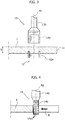
- cup-wheel tools 12 and 13 are used of the type illustrated in Figure 3 .
- the tools 12 and 13 are coaxial and rotate around one and the same axis A1.
- the plate L is machined in two distinct steps. In a first step the bottom tool 12 is operative and makes a circular incision for approximately half the thickness S of the plate L.
- the tool 12 is moved away from the plate L, and the second step can start in which the top tool 13 is brought into action and completes the incision so as to make the through hole.
- the machining tools have a cup-wheel portion 12a and 13a and a stem portion 13b for coupling with a spindle actuated by an electric motor (not illustrated in the figures) carried by a machining head of the machine.
- a milling tool 14 like the one illustrated in Figure 4 is used.
- the tool 14 has a bit 14a and a stem portion 14b for coupling with the spindle.
- the bit 14a has cutting ribbings 14a1 on its lateral portion.
- the tool 14 turns around the axis A2.
- the milling tools 14 are designed for machining laterally instead of frontally like the drilling tools 13, coming into contact with the edge of the plate throughout its thickness instead of the face of the plate as in the case of the drilling tools 13.
- the tool 14 is displaced in the direction D (see Figure 4 ), and the bit 14a removes the material throughout the thickness S of the plate L.
- the bit 14a removes the material throughout the thickness S of the plate L.
- to the right of the milling tool 14 there is the portion of plate already machined.
- Figure 5 illustrates a first embodiment of the machine according to the present invention.
- the machine comprises a bilateral machine formed by the first machine unit 3 and the second machine unit 5, interposed between which is a transfer station 4.
- a station 9 for unloading the plates.
- the machine is provided with four drilling/milling units 20 associated to the transfer station 4.
- the plates are loaded on the first machine unit 3 and are made to advance in the direction A.
- the first machine unit 3 envisages a structure with a fixed cross member 3a that supports the first array of grinding tools, and a cross member 3b mobile in the direction E, orthogonal to the direction A, which supports the second array of grinding tools. By displacing the cross member 3b that supports the second array of grinding tools in the direction E, it is possible to receive and machine plates having different transverse sizes.
- the second machine unit 5 which is similar to the first machine unit 3, also comprises a structure with a fixed cross member 5a that supports the first array of grinding tools, and a cross member 5b mobile in the direction F, orthogonal to the direction B, which supports the second array of grinding tools.
- the plate is received by the transfer station 4 at a first higher level.
- the drilling/milling unit 20 can intervene on the plate to make through holes and/or carry out milling operations. The drilling and milling operations will be described in greater detail in the sequel of the present description.
- the transfer station 4 supplies the plate to the second machine unit 5 at a second lower level.
- the plates arrive in the direction A at a higher level, and are forwarded in a direction B, orthogonal to the direction A, at a lower level.
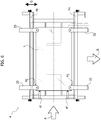
- the structure of the transfer station 4 is shown in greater detail in Figures 6 , 7 , 7A , and 8 .
- the transfer station 4 comprises a supporting structure that envisages a fixed cross member 4a and a cross member 4b mobile in the direction G orthogonal to the direction A.
- the two cross members 4a and 4b are provided with lateral means 4c for supporting and guiding the plate.
- the lateral supporting and guiding means are provided via two opposite and facing arrays of motor-driven vertical rollers 4c (see Figure 7 ), which are able to receive, support, and advance the plate in the direction A.
- the rollers 4c comprise a main body 4c1 and a peripheral edge 4c2 projecting radially outwards, resting on which are the first opposite edges of the plate L (see Figure 7A ).
- rollers 4c support and guide the first opposite edges of the plate L, which is received within the transfer unit 4 at the first higher level (see plate L' in Figure 7 ).
- Each array of rollers 4c is controlled by a single motor 4cm (see Figure 8 ) carried by the beams 4a and 4b of the supporting structure.
- the rollers 4c are mobile between an operative position where they are set close to one another (represented with a solid line), in which they support the plate L, and an inoperative position where they are set apart from one another (represented with a dashed line), in which the rollers free the edges of the plate L.
- bottom means 4e for supporting the plate go into action.
- the bottom supporting means 4e are mobile in a vertical direction, i.e., along the axis Z, within the transfer unit 4 between an operative raised position (see Figure 7A ), in which the bottom supporting means 4e are designed to take up the plate L that is located at the first higher level L' when the lateral supporting means 4c are brought into their inoperative position where they are spaced apart, and an inoperative lowered position, in which the bottom supporting means 4e are designed to deposit the plate L' at the second level L".
- the bottom supporting means 4e comprise rods 4e1 that carry at their free end a roller 4e2, which comes into contact with the bottom surface of the plate L. At the other end the rods 4e1 are carried by a structure 4e3 (see Figure 8 ) mobile underneath the transfer station 4. Ascent and descent of the rods 4e1 is controlled, for example, by hydraulic actuators of a known type (not illustrated).
- conveying means 4d are provided for conveying the plate L" in the second direction B outside the transfer unit 4.
- the conveying means 4d comprise belts 4d1, which receive the plate L on the second level L" and carry it outside the transfer station in the direction B.
- the belts 4d1 are actuated by motor-driven wheels or rollers 4d2m connected to a single motor.
- the transfer station 4 receives the plate L from the first machine unit 3 that is located upstream.
- the motor-driven rollers 4c will have a speed synchronous with the speed of advance of the first machine unit 3.
- the plate L will be stopped in a reference point coinciding with the point of deposit on the bottom level (see Figure 7 ).
- the bottom means 4e enter into action for supporting the plate, and are set in contact with the bottom surface of the plate L, which is set horizontally.
- the operations of drilling or milling are carried out, with the plate stationary and kept raised at the first level thanks to the bottom means 4e.
- the plate L is located at the first higher level supported by the bottom supporting means 4e ( Figure 7A ), and with activation of purposely provided lateral thrust elements 4g and the aid of front referencing elements 4f the plate is centred with respect to the transfer station 4.
- the drilling units 20, 21 (which work both from the bottom and from the top of the plate) will be positioned on the respective drilling co-ordinates (see Figures 9, 11 ).
- the drilling units 20 comprise a supporting structure 20a mobile in two mutually orthogonal directions (X, Y) for positioning the machining head 20b on the plate to be machined.
- the machining head 20b will be able to displace vertically along the axis Z in order to carry out the required machining operations.
- the machining head carries the drilling tools 13 (or alternatively the milling tools 14).
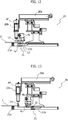
- the bottom drilling units 21 will be provided with a suction-pad body 21a, set adjacent to the drilling tool 12 (see Figures 10 and 14 ) having a top mouth provided with a peripheral sealing gasket 210 designed to come into contact with the bottom face of the plate and to render hermetic the chamber that is to be defined between the bottom face of the plate and a bottom wall 211 adjacent to the mouth of the body 21a. Giving out in 212 on the wall 211 is a duct that can be connected to a source of negative pressure.
- the suction-pad body 21a has the purpose of blocking and supporting the plate in the area around the point where the hole is to be made (see Figure 11 ). As has been illustrated, the body 21a has its top part with a C-shaped configuration, for preventing interference with the tool 12 and blocking the plate in an area adjacent to the tool 12, on three different sides.
- the drilling units 20 and 21 are mobile along three orthogonal axes thanks to the supporting structure of the transfer unit 4.
- the plate L is illustrated at the first, higher, level L', still supported by the rollers 4c.
- the bottom supporting means 4e enter into action, whilst the rollers 4c are brought into their inoperative condition, i.e., no longer in contact with the edge of the plate (see Figure 11 ).
- the bottom drilling unit 21 makes the partial hole, making an incision in the plate for approximately one half of its thickness (see Figure 11 ), and once this operation is completed, the bottom drilling unit 21 displaces from the drilling axis AF positioning itself in an area outside the drilling region (see Figure 12 ).
- the bottom drilling unit 21 comprises a slide 21b that is horizontally mobile so as to position itself underneath the bottom surface of the plate L.
- the slide 21b carries the bottom drilling tool 12, i.e., a cup grinding wheel.
- the following step envisages descent of the top drilling head 20, which will make the complete hole thanks to the top cup-wheel tool 13, thus making a through hole in the plate L.
- the top drilling head comprises a spindle pre-arranged for carrying in an interchangeable way a top drilling tool or a milling tool.
- the top drilling head 20 is brought back into a resting position like the one illustrated in Figure 10 , away from the machining area.
- the bottom machining head 21 and top machining head 20 will be positioned on the next drilling co-ordinates for carrying out a new machining operation.
- the lateral thrust elements 4g and the suction-pad body 21a will be placed in the parking position, outside the overall dimensions of the area where the plate is laid (see Figure 10 ).
- the bottom supporting means 4e will be brought into their lowered inoperative position, i.e., lower than the second lower level L".
- the bottom supporting means 4e are hence brought below the second level, i.e., below the plane constituted by the conveyor belts 4d1 (see Figure 7 ).
- the bottom supporting means 4e disappear between one belt 4d1 and the next, positioning themselves in the lowered inoperative condition.
- the plate is rested on the belts, and the belt conveyor is activated for transferring the plate towards the second machine unit 5 downstream of the transfer station.
- the next plate, coming from the first machine unit 3 set upstream, will be housed on the top level for repeating the sequence described above.
- the bottom drilling unit 21 does not carry out any machining operation while the supporting and guiding means 4c are brought into a parking position so as to allow space for the top machining head 20b, which carries in this case a milling tool (see Figure 13 ).
- the machining head 20b will be moved so as to enable execution of the desired shape.
- the plate will be brought to the second, lower, level L" and is then supplied to the second machine unit 5, for machining the second edges of the plate.
- the drilling or milling operations can be carried out on one and the same plate making an automatic tool change.
- machining operations envisage that the plate during these steps is stationary.
- these machining operations could be implemented also with the plate moving.
- the machining units 20, 21 are made to advance at the same speed at which the plate advances, in the same direction of advance and carry out the drilling or milling operations.
- the drilling/milling units are associated to a transfer unit 6 of the plates, which is set immediately downstream of the second machine unit 5.
- the operation is exactly the same, but in this case the plate reaches the transfer station 6, where it undergoes the drilling and/or milling operations, after all four sides thereof have been ground.
- the machine described herein can use abrasive tools, or else techniques for removal of stock using a jet of water at extremely high pressure, possibly with the addition of an abrasive, or with techniques that exploit sources of heat, such as for example laser.
- the drilling and milling operations are integrated and carried out in the station for transfer of the plates.
- Combination of these two operations entails a lower production cost in so far as a large part of the technology of conveyance is exploited for the drilling and milling operations, thus enabling a considerably more competitive price on the market as compared to the current state of the art.
Landscapes
- Engineering & Computer Science (AREA)
- Mechanical Engineering (AREA)
- Mining & Mineral Resources (AREA)
- Chemical & Material Sciences (AREA)
- Ceramic Engineering (AREA)
- Inorganic Chemistry (AREA)
- Processing Of Stones Or Stones Resemblance Materials (AREA)
- Re-Forming, After-Treatment, Cutting And Transporting Of Glass Products (AREA)
- Grinding And Polishing Of Tertiary Curved Surfaces And Surfaces With Complex Shapes (AREA)
Claims (9)
- Maschine zum Fräsen der Kanten von Platten, im Allgemeinen aus Glas-, Marmor- und Stein-Materialien, wobei die Maschine umfasst:- eine erste Maschinen-Einheit (3), um eine Platte (L), die bearbeitet werden soll und horizontal angeordnet ist, in eine erste Richtung (A) vorzuschieben, die im Wesentlichen parallel zu zwei ersten einander gegenüberliegenden Kanten der Platte verläuft, wobei die erste Maschinen-Einheit (3) zwei Sätze von Fräswerkzeugen (3a, 3b) umfasst, um die ersten Kanten der Platte gleichzeitig zu fräsen, während diese in der ersten Richtung (A) vorgeschoben wird;- eine zweite Maschinen-Einheit (5), die stromabwärts der ersten Einheit (3) angeordnet ist, um die Platte (L), die von der ersten Einheit (3) bearbeitet wurde, in einer zweiten Richtung (B) vorzuschieben, die senkrecht zur ersten Richtung (A) verläuft, wobei die zweite Maschinen-Einheit (5) zwei Sätze von Fräswerkzeugen (5a, 5b) umfasst, um gleichzeitig jene beiden einander gegenüberliegenden Kanten der Platte, die senkrecht zu den ersten Kanten liegen, die bereits bearbeitet wurden, zu fräsen, während die Platte (L) in der zweiten Richtung (B) vorgeschoben wird;- eine Transfer-Einheit (4, 6) für die Platten (L), dadurch gekennzeichnet, dass:- die Maschine (1) mit zumindest einer Bohr/Fräs-Einheit (20) ausgestattet ist, um auf den Platten Bohr- und/oder Fräs-Vorgänge auszuführen;- die zumindest eine Bohr/Fräs-Einheit (20) der Transfer-Einheit (4, 6) für die Platten (L) zugeordnet ist, wobei die Transfer-Einheit (4) zwischen der ersten Maschinen-Einheit (3) und der zweiten Maschinen-Einheit (5) liegt oder die Transfer-Einheit (6) unmittelbar stromabwärts der zweiten Maschinen-Einheit (5) liegt;- die Transfer-Einheit (4, 6) so ausgelegt ist, dass sie die Platten auf einem ersten höheren Niveau (L') empfängt und die Platten auf einem zweiten niedrigeren Niveau (L") bereitstellt; und- die zumindest eine Bohr/Fräs-Einheit (20) so ausgelegt ist, dass sie auf einer Platte (L) dann Bohr- und/oder Fräs-Vorgänge ausführt, wenn sich die Platte in der Transfer-Einheit (4, 6) auf dem ersten höheren Niveau (L') befindet.
- Maschine gemäß Anspruch 1, wobei die Transfer-Einheit umfasst:- eine Tragstruktur (4a, 4b);- seitliche Einrichtungen (4c), um die Platte, die von der Tragstruktur getragen wird, zu tragen und zu führen, um die ersten einander gegenüberliegenden Kanten einer Platte (L), die in der Transfer-Einheit (4, 6) auf dem ersten höheren Niveau (L`) aufgenommen wurde, zu tragen und zu führen, wobei die seitlichen Trag-Einrichtungen (4c) zwischen einer Betriebsstellung (A3), in der sie nahe beieinander liegen, zu einer Ruhestellung (A3', A3") bewegt werden können, in der sie voneinander beabstandet sind;- untere Trageinrichtungen (4e) zum Tragen der Platte (L), wobei die unteren Trageinrichtungen innerhalb der Transfer-Einheit (4, 6) zwischen einer angehobenen Betriebsstellung, in der die unteren Trageinrichtungen so ausgelegt sind, dass sie eine Platte aufnehmen, die auf dem ersten höheren Niveau (L') angeordnet ist, wenn die seitlichen Trageinrichtungen in ihre Ruhestellung gebracht wurden, und einer abgesenkten Ruhestellung bewegt werden können, in der die unteren Trageinrichtungen so ausgelegt sind, dass sie die Platte auf dem zweiten Niveau (L") ablegen, wobei Transport-Einrichtungen (4d) vorgesehen sind, um die Platte (L) in der zweiten Richtung (B) aus der Transfer-Einheit (4, 6) zu transportieren,wobei die Maschine dadurch gekennzeichnet ist, dass der Tragstruktur (4a, 4b) zumindest eine Bohr/Fräs-Einheit (20) zugeordnet ist, die so vorangeordnet wird, dass sie dazu ausgelegt ist, dass sie die Bohr- und/oder Fräs-Vorgänge auf der Platte (L) dann ausführt, wenn diese von den unteren Trageinrichtungen (4e) auf ihrem ersten höheren Niveau (L') gehalten wird und sich die seitlichen Trageinrichtungen in ihrer Ruhestellung (A3`, A3") befinden.
- Maschine gemäß Anspruch 2, dadurch gekennzeichnet, dass die zumindest eine Bohr/Fräs-Einheit (20) zumindest ein mit einer Saugwirkung arbeitendes Arretier-Element (21a) umfasst, das so ausgelegt ist, dass es mit einer Fläche der Platte (L) in Berührung gebracht werden kann, um die Platte in ihrer Stellung zu arretieren, während die Bohr/Fräs-Vorgänge ausgeführt werden.
- Maschine gemäß Anspruch 3, dadurch gekennzeichnet, dass die zumindest eine Bohr/Fräs-Einheit (20) einen oberen Bohrkopf (20b) sowie einen untere Bohrkopf (21) umfasst, die so ausgebildet sind, dass sie miteinander zusammenwirken, um in den Platten kreisförmige Öffnungen auszubilden, wobei sowohl der obere Kopf (20b) als auch der untere Kopf (21) von der Tragstruktur der Transfer-Einheit (4, 6) so getragen werden, dass sie entlang von drei aufeinander senkrecht stehenden Achsen ausgelenkt werden können.
- Maschine gemäß Anspruch 4, dadurch gekennzeichnet, dass der obere Bohrkopf (20b) eine Welle umfasst, die so ausgelegt ist, dass sie ein oberes Bohrwerkzeug (13) oder ein Fräswerkzeug (14) trägt.
- Maschine gemäß Anspruch 4, dadurch gekennzeichnet, dass das obere Bohrwerkzeug (20b) mit Mittel zum Abgeben eines abtragenden Hochdruck-Wasserstrahls versehen ist, die einen unter einem extrem hohen Druck stehenden Wasserstrahl verwenden, dem wahlweise ein Schleifmittel beigegeben ist.
- Maschine gemäß Anspruch 4, dadurch gekennzeichnet, dass der obere Bohrkopf (20b) mit abtragenden Mitteln versehen ist, die mithilfe von Wärme arbeiten und wärmeerzeugende Quellen verwenden, wie etwa einen Laser.
- Maschine gemäß irgendeinem der Ansprüche 2 bis 7, dadurch gekennzeichnet, dass die seitlichen Einrichtungen (4c) zum Tragen und Führen der Platte (L) zwei einander gegenüberliegende und zueinander gerichtete Sätze von motorgetriebenen vertikalen Rollen (4c) umfassen.
- Maschine gemäß Anspruch 8, dadurch gekennzeichnet, dass zumindest einer der Sätze von Rollen (4c) horizontal so ausgelenkt werden kann, dass er vom anderen Satz weg und/oder auf den anderen Satz zu bewegt werden kann, sodass Platten aufgenommen werden können, die verschieden groß sind.
Applications Claiming Priority (1)
| Application Number | Priority Date | Filing Date | Title |
|---|---|---|---|
| IT000630A ITTO20120630A1 (it) | 2012-07-17 | 2012-07-17 | Macchina per la molatura dei bordi di lastre di vetro, marmo e materiali lapidei in genere, con gruppo di foratura/fresatura integrato |
Publications (2)
| Publication Number | Publication Date |
|---|---|
| EP2687327A1 EP2687327A1 (de) | 2014-01-22 |
| EP2687327B1 true EP2687327B1 (de) | 2017-03-22 |
Family
ID=46758944
Family Applications (1)
| Application Number | Title | Priority Date | Filing Date |
|---|---|---|---|
| EP13176353.4A Active EP2687327B1 (de) | 2012-07-17 | 2013-07-12 | Vorrichtung zum Schleifen der Ränder von Glasplatten, Marmor und Gesteinsmaterialien im Allgemeinen, mit integrierter Bohr-/Fräseinheit |
Country Status (3)
| Country | Link |
|---|---|
| EP (1) | EP2687327B1 (de) |
| CN (1) | CN103538154B (de) |
| IT (1) | ITTO20120630A1 (de) |
Families Citing this family (13)
| Publication number | Priority date | Publication date | Assignee | Title |
|---|---|---|---|---|
| EP3045281B1 (de) * | 2015-01-16 | 2017-11-01 | Forel Spa | Automatische maschine zum bohren und fräsen von vertikal angeordneten glasscheiben und seine benutzung |
| CN105382939A (zh) * | 2015-12-11 | 2016-03-09 | 常州华美光伏材料有限公司 | 一种光伏组件背板玻璃在线串联式钻孔系统 |
| ITUA20161572A1 (it) * | 2016-03-11 | 2016-06-11 | Forvet S R L | Macchina per la lavorazione di lastre di vetro e relativo procedimento di produzione |
| CN109070303A (zh) | 2016-03-11 | 2018-12-21 | 福威特研发有限公司 | 具有计算机化数控组件的用于加工玻璃板的机器及相关生产方法 |
| ITUA20161575A1 (it) * | 2016-03-11 | 2016-06-11 | Forvet S R L | Macchina per la lavorazione di lastre di vetro con un gruppo a controllo numerico computerizzato e relativo procedimento di produzione |
| IT201600079005A1 (it) | 2016-07-27 | 2018-01-27 | Elettromeccanica Bovone Srl | Apparato modulare e metodo per la lavorazione di lastre piane |
| CN106181727A (zh) * | 2016-08-23 | 2016-12-07 | 尚琳涵 | 一种免抹灰砌砖的加工设备 |
| CN110815589A (zh) * | 2019-11-28 | 2020-02-21 | 刘洋 | 一种玻璃自动打孔磨边装置 |
| CN114559561A (zh) * | 2022-03-03 | 2022-05-31 | 云浮市科特机械有限公司 | 全自动开孔磨孔机 |
| CN114536016B (zh) * | 2022-03-24 | 2023-09-08 | 福建华韵竹木有限公司 | 菜板自动铣边及钻孔攻丝加工设备及其加工方法 |
| CN115383915A (zh) * | 2022-09-02 | 2022-11-25 | 山东建筑大学 | 一种用于基板加工的预处理装置 |
| CN115351649A (zh) * | 2022-09-15 | 2022-11-18 | 兆虹精密(北京)科技有限公司 | 玻璃雕铣机机架及相应的玻璃雕铣机 |
| CN117817482B (zh) * | 2024-03-04 | 2024-05-28 | 南安市奥力石业有限公司 | 一种石材连续自动磨削加工工艺及加工设备 |
Family Cites Families (6)
| Publication number | Priority date | Publication date | Assignee | Title |
|---|---|---|---|---|
| FR2666802B1 (fr) * | 1990-09-19 | 1993-07-16 | Saint Gobain Vitrage Int | Preparation de plaques de verre faconnees avec commande numerique. |
| ITMI991382A1 (it) * | 1999-06-21 | 2000-12-21 | Bavelloni Z Spa | Macchina automatica bilaterale per la lavorazione dei bordi di lastredi vetro materiali lapidei e simili |
| ITTO20020841A1 (it) * | 2002-09-25 | 2004-03-26 | Biesse Spa | Apparato per la foratura di lastre di vetro, marmo e simili materiali lapidei. |
| ITTV20040056U1 (it) * | 2004-10-20 | 2005-01-20 | Dario Toncelli | Macchina tagliatrice combinata per la lavorazione di materiale in lastra. |
| CN2860743Y (zh) * | 2006-01-19 | 2007-01-24 | 青岛双星铸造机械有限公司 | 连杆强化抛丸清理机 |
| IT1392110B1 (it) * | 2008-12-10 | 2012-02-09 | Biesse Spa | Procedimento e macchina per eseguire operazioni di troncaggio di lastre di vetro stratificato lungo linee prestabilite |
-
2012
- 2012-07-17 IT IT000630A patent/ITTO20120630A1/it unknown
-
2013
- 2013-07-12 EP EP13176353.4A patent/EP2687327B1/de active Active
- 2013-07-17 CN CN201310442469.6A patent/CN103538154B/zh active Active
Non-Patent Citations (1)
| Title |
|---|
| None * |
Also Published As
| Publication number | Publication date |
|---|---|
| CN103538154B (zh) | 2017-08-04 |
| ITTO20120630A1 (it) | 2014-01-18 |
| EP2687327A1 (de) | 2014-01-22 |
| CN103538154A (zh) | 2014-01-29 |
Similar Documents
| Publication | Publication Date | Title |
|---|---|---|
| EP2687327A1 (de) | Vorrichtung zum Schleifen der Ränder von Glasplatten, Marmor und Gesteinsmaterialien im Allgemeinen, mit integrierter Bohr-/Fräseinheit | |
| US20080110311A1 (en) | Multiple-tool machine for combined cutting of slabs of hard material | |
| KR102458884B1 (ko) | 수직으로 배치되는 유리판을 자동적으로 드릴링하고 밀링하기 위한 자동 기계 및 방법 | |
| EP2998088B1 (de) | Arbeitsstation einer Maschine für Steinplatten, Marmor, Kunststoff, oder dergleichen, mit einer Opfermaterialarbeitsebene | |
| CN103692311B (zh) | 全自动卧式玻璃直线四边磨边机及其磨边加工方法 | |
| EP3106275B1 (de) | Maschine und verfahren zur bearteitung von platten | |
| CN101687306B (zh) | 多线锯以及坯料切断方法 | |
| RU2292312C2 (ru) | Устройство для обработки плит материала | |
| US9339872B2 (en) | Machining apparatus and deburring device | |
| EP0217658A1 (de) | Glasplatten-Fertigungsmaschine | |
| US20170305035A1 (en) | Machine for cutting stone material | |
| EP3172013B1 (de) | Verfahren zum glätten und/oder polieren von platten aus stein oder einem steinartigen material | |
| EP1740359A1 (de) | Kombinierte vorrichtung zur bearbeitung von artikeln, insbesondere in der form von platten | |
| CN102189461A (zh) | 一种全自动卧式玻璃四边直线磨边机 | |
| US20130284564A1 (en) | Conveyor for elongated workpieces | |
| KR101469654B1 (ko) | 유리판의 가공 방법 및 유리판의 가공 장치 | |
| US7240415B2 (en) | Machine for processing material in the form of slabs, in particular natural stone material, ceramic material and conglomerate | |
| JP2018058206A (ja) | ガラス板の加工装置 | |
| CN202088051U (zh) | 一种全自动卧式玻璃四边直线磨边机 | |
| US4410025A (en) | Method and apparatus for making wooden chair seats | |
| EP4049787B1 (de) | Maschine und verfahren zum bearbeiten von seitenkanten von glasplatten, steinplatten oder kunststoffplatten | |
| KR100957609B1 (ko) | 브이홈 전용 가공기 | |
| KR101071238B1 (ko) | 인풋샤프트의 가공방법 | |
| ITTV970007U1 (it) | Macchina per il taglio ottimizzato di lastre di materiale lapideo. | |
| WO2016142822A1 (en) | Apparatus for processing of glass plates |
Legal Events
| Date | Code | Title | Description |
|---|---|---|---|
| PUAI | Public reference made under article 153(3) epc to a published international application that has entered the european phase |
Free format text: ORIGINAL CODE: 0009012 |
|
| AK | Designated contracting states |
Kind code of ref document: A1 Designated state(s): AL AT BE BG CH CY CZ DE DK EE ES FI FR GB GR HR HU IE IS IT LI LT LU LV MC MK MT NL NO PL PT RO RS SE SI SK SM TR |
|
| AX | Request for extension of the european patent |
Extension state: BA ME |
|
| 17P | Request for examination filed |
Effective date: 20140702 |
|
| RBV | Designated contracting states (corrected) |
Designated state(s): AL AT BE BG CH CY CZ DE DK EE ES FI FR GB GR HR HU IE IS IT LI LT LU LV MC MK MT NL NO PL PT RO RS SE SI SK SM TR |
|
| GRAP | Despatch of communication of intention to grant a patent |
Free format text: ORIGINAL CODE: EPIDOSNIGR1 |
|
| STAA | Information on the status of an ep patent application or granted ep patent |
Free format text: STATUS: GRANT OF PATENT IS INTENDED |
|
| RIC1 | Information provided on ipc code assigned before grant |
Ipc: B28D 1/14 20060101ALI20161006BHEP Ipc: B28D 1/18 20060101ALI20161006BHEP Ipc: B24B 9/10 20060101AFI20161006BHEP |
|
| INTG | Intention to grant announced |
Effective date: 20161108 |
|
| GRAS | Grant fee paid |
Free format text: ORIGINAL CODE: EPIDOSNIGR3 |
|
| GRAA | (expected) grant |
Free format text: ORIGINAL CODE: 0009210 |
|
| STAA | Information on the status of an ep patent application or granted ep patent |
Free format text: STATUS: THE PATENT HAS BEEN GRANTED |
|
| AK | Designated contracting states |
Kind code of ref document: B1 Designated state(s): AL AT BE BG CH CY CZ DE DK EE ES FI FR GB GR HR HU IE IS IT LI LT LU LV MC MK MT NL NO PL PT RO RS SE SI SK SM TR |
|
| REG | Reference to a national code |
Ref country code: GB Ref legal event code: FG4D |
|
| REG | Reference to a national code |
Ref country code: CH Ref legal event code: EP Ref country code: CH Ref legal event code: NV Representative=s name: ISLER AND PEDRAZZINI AG, CH |
|
| REG | Reference to a national code |
Ref country code: AT Ref legal event code: REF Ref document number: 877242 Country of ref document: AT Kind code of ref document: T Effective date: 20170415 |
|
| REG | Reference to a national code |
Ref country code: IE Ref legal event code: FG4D |
|
| REG | Reference to a national code |
Ref country code: DE Ref legal event code: R096 Ref document number: 602013018800 Country of ref document: DE |
|
| REG | Reference to a national code |
Ref country code: NL Ref legal event code: MP Effective date: 20170322 |
|
| PG25 | Lapsed in a contracting state [announced via postgrant information from national office to epo] |
Ref country code: LT Free format text: LAPSE BECAUSE OF FAILURE TO SUBMIT A TRANSLATION OF THE DESCRIPTION OR TO PAY THE FEE WITHIN THE PRESCRIBED TIME-LIMIT Effective date: 20170322 Ref country code: GR Free format text: LAPSE BECAUSE OF FAILURE TO SUBMIT A TRANSLATION OF THE DESCRIPTION OR TO PAY THE FEE WITHIN THE PRESCRIBED TIME-LIMIT Effective date: 20170623 Ref country code: HR Free format text: LAPSE BECAUSE OF FAILURE TO SUBMIT A TRANSLATION OF THE DESCRIPTION OR TO PAY THE FEE WITHIN THE PRESCRIBED TIME-LIMIT Effective date: 20170322 Ref country code: FI Free format text: LAPSE BECAUSE OF FAILURE TO SUBMIT A TRANSLATION OF THE DESCRIPTION OR TO PAY THE FEE WITHIN THE PRESCRIBED TIME-LIMIT Effective date: 20170322 Ref country code: NO Free format text: LAPSE BECAUSE OF FAILURE TO SUBMIT A TRANSLATION OF THE DESCRIPTION OR TO PAY THE FEE WITHIN THE PRESCRIBED TIME-LIMIT Effective date: 20170622 |
|
| REG | Reference to a national code |
Ref country code: LT Ref legal event code: MG4D |
|
| PG25 | Lapsed in a contracting state [announced via postgrant information from national office to epo] |
Ref country code: RS Free format text: LAPSE BECAUSE OF FAILURE TO SUBMIT A TRANSLATION OF THE DESCRIPTION OR TO PAY THE FEE WITHIN THE PRESCRIBED TIME-LIMIT Effective date: 20170322 Ref country code: LV Free format text: LAPSE BECAUSE OF FAILURE TO SUBMIT A TRANSLATION OF THE DESCRIPTION OR TO PAY THE FEE WITHIN THE PRESCRIBED TIME-LIMIT Effective date: 20170322 Ref country code: BG Free format text: LAPSE BECAUSE OF FAILURE TO SUBMIT A TRANSLATION OF THE DESCRIPTION OR TO PAY THE FEE WITHIN THE PRESCRIBED TIME-LIMIT Effective date: 20170622 Ref country code: SE Free format text: LAPSE BECAUSE OF FAILURE TO SUBMIT A TRANSLATION OF THE DESCRIPTION OR TO PAY THE FEE WITHIN THE PRESCRIBED TIME-LIMIT Effective date: 20170322 |
|
| PG25 | Lapsed in a contracting state [announced via postgrant information from national office to epo] |
Ref country code: NL Free format text: LAPSE BECAUSE OF FAILURE TO SUBMIT A TRANSLATION OF THE DESCRIPTION OR TO PAY THE FEE WITHIN THE PRESCRIBED TIME-LIMIT Effective date: 20170322 |
|
| PG25 | Lapsed in a contracting state [announced via postgrant information from national office to epo] |
Ref country code: EE Free format text: LAPSE BECAUSE OF FAILURE TO SUBMIT A TRANSLATION OF THE DESCRIPTION OR TO PAY THE FEE WITHIN THE PRESCRIBED TIME-LIMIT Effective date: 20170322 Ref country code: RO Free format text: LAPSE BECAUSE OF FAILURE TO SUBMIT A TRANSLATION OF THE DESCRIPTION OR TO PAY THE FEE WITHIN THE PRESCRIBED TIME-LIMIT Effective date: 20170322 Ref country code: ES Free format text: LAPSE BECAUSE OF FAILURE TO SUBMIT A TRANSLATION OF THE DESCRIPTION OR TO PAY THE FEE WITHIN THE PRESCRIBED TIME-LIMIT Effective date: 20170322 Ref country code: SK Free format text: LAPSE BECAUSE OF FAILURE TO SUBMIT A TRANSLATION OF THE DESCRIPTION OR TO PAY THE FEE WITHIN THE PRESCRIBED TIME-LIMIT Effective date: 20170322 Ref country code: CZ Free format text: LAPSE BECAUSE OF FAILURE TO SUBMIT A TRANSLATION OF THE DESCRIPTION OR TO PAY THE FEE WITHIN THE PRESCRIBED TIME-LIMIT Effective date: 20170322 |
|
| PG25 | Lapsed in a contracting state [announced via postgrant information from national office to epo] |
Ref country code: PT Free format text: LAPSE BECAUSE OF FAILURE TO SUBMIT A TRANSLATION OF THE DESCRIPTION OR TO PAY THE FEE WITHIN THE PRESCRIBED TIME-LIMIT Effective date: 20170724 Ref country code: SM Free format text: LAPSE BECAUSE OF FAILURE TO SUBMIT A TRANSLATION OF THE DESCRIPTION OR TO PAY THE FEE WITHIN THE PRESCRIBED TIME-LIMIT Effective date: 20170322 Ref country code: IS Free format text: LAPSE BECAUSE OF FAILURE TO SUBMIT A TRANSLATION OF THE DESCRIPTION OR TO PAY THE FEE WITHIN THE PRESCRIBED TIME-LIMIT Effective date: 20170722 Ref country code: PL Free format text: LAPSE BECAUSE OF FAILURE TO SUBMIT A TRANSLATION OF THE DESCRIPTION OR TO PAY THE FEE WITHIN THE PRESCRIBED TIME-LIMIT Effective date: 20170322 |
|
| REG | Reference to a national code |
Ref country code: DE Ref legal event code: R097 Ref document number: 602013018800 Country of ref document: DE |
|
| PLBE | No opposition filed within time limit |
Free format text: ORIGINAL CODE: 0009261 |
|
| STAA | Information on the status of an ep patent application or granted ep patent |
Free format text: STATUS: NO OPPOSITION FILED WITHIN TIME LIMIT |
|
| PG25 | Lapsed in a contracting state [announced via postgrant information from national office to epo] |
Ref country code: DK Free format text: LAPSE BECAUSE OF FAILURE TO SUBMIT A TRANSLATION OF THE DESCRIPTION OR TO PAY THE FEE WITHIN THE PRESCRIBED TIME-LIMIT Effective date: 20170322 |
|
| 26N | No opposition filed |
Effective date: 20180102 |
|
| PG25 | Lapsed in a contracting state [announced via postgrant information from national office to epo] |
Ref country code: SI Free format text: LAPSE BECAUSE OF FAILURE TO SUBMIT A TRANSLATION OF THE DESCRIPTION OR TO PAY THE FEE WITHIN THE PRESCRIBED TIME-LIMIT Effective date: 20170322 |
|
| GBPC | Gb: european patent ceased through non-payment of renewal fee |
Effective date: 20170712 |
|
| REG | Reference to a national code |
Ref country code: IE Ref legal event code: MM4A |
|
| REG | Reference to a national code |
Ref country code: FR Ref legal event code: ST Effective date: 20180330 |
|
| PG25 | Lapsed in a contracting state [announced via postgrant information from national office to epo] |
Ref country code: IE Free format text: LAPSE BECAUSE OF NON-PAYMENT OF DUE FEES Effective date: 20170712 Ref country code: GB Free format text: LAPSE BECAUSE OF NON-PAYMENT OF DUE FEES Effective date: 20170712 |
|
| PG25 | Lapsed in a contracting state [announced via postgrant information from national office to epo] |
Ref country code: FR Free format text: LAPSE BECAUSE OF NON-PAYMENT OF DUE FEES Effective date: 20170731 |
|
| REG | Reference to a national code |
Ref country code: BE Ref legal event code: MM Effective date: 20170731 |
|
| PG25 | Lapsed in a contracting state [announced via postgrant information from national office to epo] |
Ref country code: LU Free format text: LAPSE BECAUSE OF NON-PAYMENT OF DUE FEES Effective date: 20170712 |
|
| PG25 | Lapsed in a contracting state [announced via postgrant information from national office to epo] |
Ref country code: BE Free format text: LAPSE BECAUSE OF NON-PAYMENT OF DUE FEES Effective date: 20170731 |
|
| PG25 | Lapsed in a contracting state [announced via postgrant information from national office to epo] |
Ref country code: MT Free format text: LAPSE BECAUSE OF NON-PAYMENT OF DUE FEES Effective date: 20170712 |
|
| PG25 | Lapsed in a contracting state [announced via postgrant information from national office to epo] |
Ref country code: HU Free format text: LAPSE BECAUSE OF FAILURE TO SUBMIT A TRANSLATION OF THE DESCRIPTION OR TO PAY THE FEE WITHIN THE PRESCRIBED TIME-LIMIT; INVALID AB INITIO Effective date: 20130712 Ref country code: MC Free format text: LAPSE BECAUSE OF FAILURE TO SUBMIT A TRANSLATION OF THE DESCRIPTION OR TO PAY THE FEE WITHIN THE PRESCRIBED TIME-LIMIT Effective date: 20170322 |
|
| PG25 | Lapsed in a contracting state [announced via postgrant information from national office to epo] |
Ref country code: CY Free format text: LAPSE BECAUSE OF NON-PAYMENT OF DUE FEES Effective date: 20170322 |
|
| PG25 | Lapsed in a contracting state [announced via postgrant information from national office to epo] |
Ref country code: MK Free format text: LAPSE BECAUSE OF FAILURE TO SUBMIT A TRANSLATION OF THE DESCRIPTION OR TO PAY THE FEE WITHIN THE PRESCRIBED TIME-LIMIT Effective date: 20170322 |
|
| PG25 | Lapsed in a contracting state [announced via postgrant information from national office to epo] |
Ref country code: TR Free format text: LAPSE BECAUSE OF FAILURE TO SUBMIT A TRANSLATION OF THE DESCRIPTION OR TO PAY THE FEE WITHIN THE PRESCRIBED TIME-LIMIT Effective date: 20170322 |
|
| PG25 | Lapsed in a contracting state [announced via postgrant information from national office to epo] |
Ref country code: AL Free format text: LAPSE BECAUSE OF FAILURE TO SUBMIT A TRANSLATION OF THE DESCRIPTION OR TO PAY THE FEE WITHIN THE PRESCRIBED TIME-LIMIT Effective date: 20170322 |
|
| REG | Reference to a national code |
Ref country code: AT Ref legal event code: UEP Ref document number: 877242 Country of ref document: AT Kind code of ref document: T Effective date: 20170322 |
|
| PGFP | Annual fee paid to national office [announced via postgrant information from national office to epo] |
Ref country code: DE Payment date: 20250728 Year of fee payment: 13 |
|
| PGFP | Annual fee paid to national office [announced via postgrant information from national office to epo] |
Ref country code: IT Payment date: 20250704 Year of fee payment: 13 |
|
| PGFP | Annual fee paid to national office [announced via postgrant information from national office to epo] |
Ref country code: AT Payment date: 20250718 Year of fee payment: 13 |
|
| PGFP | Annual fee paid to national office [announced via postgrant information from national office to epo] |
Ref country code: CH Payment date: 20250801 Year of fee payment: 13 |