EP2687404B1 - Agencement de sécurisation de chargement - Google Patents
Agencement de sécurisation de chargement Download PDFInfo
- Publication number
- EP2687404B1 EP2687404B1 EP13003557.9A EP13003557A EP2687404B1 EP 2687404 B1 EP2687404 B1 EP 2687404B1 EP 13003557 A EP13003557 A EP 13003557A EP 2687404 B1 EP2687404 B1 EP 2687404B1
- Authority
- EP
- European Patent Office
- Prior art keywords
- assembly
- loading area
- travel
- crossbeam
- securing
- Prior art date
- Legal status (The legal status is an assumption and is not a legal conclusion. Google has not performed a legal analysis and makes no representation as to the accuracy of the status listed.)
- Active
Links
Images


Classifications
-
- B—PERFORMING OPERATIONS; TRANSPORTING
- B60—VEHICLES IN GENERAL
- B60P—VEHICLES ADAPTED FOR LOAD TRANSPORTATION OR TO TRANSPORT, TO CARRY, OR TO COMPRISE SPECIAL LOADS OR OBJECTS
- B60P7/00—Securing or covering of load on vehicles
- B60P7/06—Securing of load
- B60P7/08—Securing to the vehicle floor or sides
- B60P7/0892—Securing to the vehicle floor or sides by preventing lateral movement of the load, e.g. using stop blocks
Definitions
- the invention relates to an arrangement for securing cargo on commercial vehicles which has at least two beams oriented transversely to the direction of travel, in each case via fastening means with laterally provided on the longitudinal outer side edges of the cargo bed of the commercial vehicle provided with holes mounting rails connected and with respect to the vehicle longitudinal direction in different positions can be locked on the mounting rails, wherein the aligned transversely to the direction of travel bars are provided over their length with hole receptacles for holding further cargo securing elements and at least partially rest in their locked with the mounting rail locked position on the bed and their attachment means the longitudinal outer edge of the cargo area across in the Engage holes in the mounting rail.
- Arrangements for securing cargo are known in various configurations. These serve, in particular, objects positioned on a commercial vehicle loading area how to secure boxes, transport pallets and the like load during a commercial vehicle ride against unintentional movements.
- the beams oriented transversely to the vehicle direction are to be fastened to retaining means provided with holes in the form of holes provided with holes at the sides of the longitudinal outer side edges of the loading surface, so that the beams oriented transversely to the vehicle direction can be locked in different positions and positions on the loading surface on these fastening rails.
- the disadvantage here is that although the charge can be lashed by means of lashing straps in the vehicle longitudinal direction, but at lateral accelerations, e.g. during cornering, the load is secured only against the lashing forces against slipping sideways, which is very time consuming. Additional fittings such as pillows or similar filling material as load securing are also very time-consuming to install and take up storage space.
- This arrangement for load securing is very complex and builds extremely high. This high altitude is often desired in transporting cylindrical cargo. However, if goods to be transported on pallets are to be secured, this type of load securing is useless.
- the arrangement for securing cargo of the type mentioned is characterized in that as a further load securing element aligned parallel to the direction of the sword beam is provided, the fastening elements, which can be fixed to two adjacent spaced apart, aligned transversely to the direction of beam are.
- an arrangement for securing cargo in which continue to the recordings of transversely aligned to the vehicle direction beam lashing straps or other Verspannmitttel, which are aligned in the vehicle longitudinal direction, can be attached.
- the sword bar must be ensured by the sword bar that positioned on the commercial vehicle loading goods are prevented by the sword bar against movements transverse to the vehicle longitudinal direction. For this they are at the corresponding cargo goods, such as boxes, transport pallets and the like.
- the sword bars are each provided with two spaced from each other on the bed transom, so the beam, transverse to the vehicle longitudinal direction aligned. These are preferably designed such that the sword bar overlap the crossbars.
- the swordbeams preferably have corresponding recesses, so that the recesses extend over and surround the crossbeams, so that the crossbeams dive into the respective recess and are located in them after assembly.
- a sword bar may also have a plurality of recesses for the respective crossbar to allow for different distance measurements with one and the same sword bar can.
- the crossbars are as in the prior art in different positions to be attached to the support means of the Nutzhuslade configuration, namely in the corresponding spaced-apart holes in the mounting rail.
- a transversely aligned to the vehicle direction beam (crossbar) at one end have a fixed hook-shaped connection, which is to be introduced into a corresponding hole of the mounting rail on one side of the commercial vehicle area.
- On the opposite side of the crossbar may have a pivotable, latch-shaped hook closure, which is to introduce after positioning a crossbar by a pivoting movement in the corresponding hole recess of the opposite mounting rail of the commercial vehicle area and there via a mechanical securing element, such as a bracket, can be secured.
- the respective sword bar is to be introduced into the corresponding hole recesses on the upper side or also on its outer surfaces of the crossbar, and if necessary can also be secured there.
- matching parts are provided with matching reference numerals.
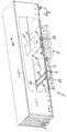
- FIG. 1 apparent commercial vehicle quantified in the form of a provided with side panels 2, a roof 3 and rear doors 4 semi-trailer, which has a chassis 5 and a loading area 6.
- the side of the loading area 6 is provided with a mounting rail 7 as a securing means for load securing elements fixed to the loading area 6 is connected and spaced apart holes 8 has. At these holes 8 are aligned transversely to the direction 9 aligned beams 10, so that the distance between two bars can be changed to each other and this can be arranged at almost any point on the bed.
- Fig. 1 the side tarpaulin 2 is shown partially cut out, so that the interior is visible.
- two transport boxes 11 are arranged as an example, which are placed on feet 12. These are each bounded by the transversely to the transport direction 9 formed beam 10 in the illustrated embodiment, so that the crossbar 10 abut the mutually facing side surfaces of the pallet feet 12 and thus prevent movement of the transport boxes 11 in and against the direction of travel 9.
- the aligned transversely to the direction of travel 9 beams 10 have not only on their side surfaces provided with spaced hole recesses 10.2, but on its upper side, as shown in the illustration Fig. 1 in the two provided in the left area crossbar 10 can be seen.
- the sword bar 13 are provided.
- One of these sword bar 13, which is mounted on the crossbar 10, is also visible in front of the feet 12 of the first transport box 11, so that the two feet 22 of the transport box 11 also bears against this sword bar 13, so that the transport box 11 also against movement transversely are secured to the vehicle longitudinal direction 9 by positive locking.
- each crossbar has on its top and in its side areas hole recesses 10.1 and 10.2, wherein the sword bar 13 can engage with its fasteners 15 in the upper hole recesses 10.2.
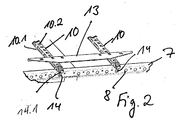
- the bars 10 each have a fixed hook-shaped end as a fastening element 14 (on the other not visible side) and a hook-shaped pivotable latch 14.1, the in Fig. 2 is shown in its mounting position. In the assembly position, the bolt 14 is replaced by a securing element 14.1 (FIG. Fig. 4 ), so that a seätige Hochschwenkamba is prevented. Thus, the beam 10 is secured secured to the mounting rail 7.
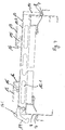
- the Fig. 3 and 4 show in a cross-sectional view through the crossbar 10 and the loading area 6 the crossbar 10 and the sword bar 13 in the mounted position and in a position in which the crossbar 10 unlocked and the Sword beam 13 are dismantled.
- the crossbar 10 has the already mentioned distributed over the length arranged hole recesses 10.2 and 10.1.
- On both sides of the crossbar 10 each have a sword bar 13 is provided.
- Each sword bar 13 has two bent fasteners 15, one of which is to be inserted into the corresponding hole recess 10.2 or 10.1. It can be seen that each sword bar 13 has a stop surface 16 which is oriented towards the commercial vehicle loading area 6. For this purpose, one end of the sword bar 13 is bent.
- This abutment surface 16 may fit positively, for example, on the pallet base 12 of a pallet or a transport box 11.
- the in Fig. 3 and 4 left lever of the crossbar 10 is formed as a pivot lever 14.
- this pivot lever 14 is shown in the assembled position, in which its hook-shaped end engages in the hole recess 8 of the mounting rail 7.
- the lever 14 in Fig. 4 is shown in the disassembly position pivoted closure bracket 14.1.
- the sword bar 13 are shown in the disassembled position.
- FIGS. 5 and 6 is a sword bar 13 each shown in different perspective views.
- the stop surface 16 is angled.
- recesses 17 can be seen in the mounted state of the parts (see also Fig. 2 ) can be penetrated by a cross bar 10, wherein through the total of four provided recesses 17 for two cross bars 10 both on one side of the sword beam 13 as well as on the other side of the sword bar 13, a different distance dimension of the crossbars 10 to each other on the sword bar 13 can be considered.
- 17 two cranked fastener 15 are provided in each recess, to take into account this distance measure accordingly.
Landscapes
- Engineering & Computer Science (AREA)
- Transportation (AREA)
- Mechanical Engineering (AREA)
- Fittings On The Vehicle Exterior For Carrying Loads, And Devices For Holding Or Mounting Articles (AREA)
Claims (7)
- Dispositif d'arrimage de charges sur des véhicules utilitaires (1), le dispositif comprenant au moins deux barres (10) qui sont orientées transversalement à la direction de déplacement (9) et qui peuvent être reliées chacune, par le biais de moyens de fixation (14), à des rails de fixation (7) pourvus de trous et prévus de manière fixe latéralement aux bords latéraux extérieurs longitudinaux de la surface de chargement (6) du véhicule utilitaire et qui peuvent être bloquées dans différentes positions sur les rails de fixation (7) par rapport à la direction longitudinale du véhicule (9), les barres (10) orientées transversalement à la direction de roulement (9) étant pourvues, de manière répartie sur leur longueur, de trous de réception (10.1, 10.2) destinés au montage d'autres éléments d'arrimage de charge et, dans leur position bloquée reliée au rail de fixation (7), s'appuient au moins partiellement sur la surface de chargement (6) et leurs moyens de fixation (14) s'engagent dans les trous ménagés dans le rail de fixation (7) en s'engageant par-dessous le bord extérieur longitudinal de la surface de chargement (6), caractérisé en ce qu'il est prévu comme autre élément d'arrimage de charge une barre diagonale (13) qui est orientée parallèlement à la direction de roulement (9) et qui comporte des éléments de fixation (15) qui peuvent être fixés à deux barres (10) adjacentes, espacées l'une de l'autre, et orientées transversalement à la direction de roulement (9).
- Dispositif d'arrimage de charge selon la revendication 1, caractérisé en ce que la barre diagonale (13) comporte une surface de butée (16) orientée orthogonalement à la surface de chargement (6) du véhicule utilitaire (1).
- Dispositif d'arrimage de charge selon la revendication 1 ou 2, caractérisé en ce que la barre diagonale (13) comporte des éléments de fixation (15) destinés à être inséré dans les évidements (10.2) de deux barres (10) formées transversalement à la direction de roulement (9).
- Dispositif d'arrimage de charge selon la revendication 2 ou 3, caractérisé en ce qu'une barre diagonale (13) comporte, dans la surface de butée (16) orientée orthogonalement à la surface de chargement de véhicule utilitaire (6), au moins deux évidements (17), espacés l'un de l'autre, dans lesquels les barres adjacentes (10), orientées transversalement à la direction de roulement (9), s'engagent lorsque la barre diagonale (13) est montée.
- Dispositif d'arrimage de charge selon la revendication 4, caractérisé en ce qu'il est prévu, pour chaque barre (10) orientée transversalement à la direction de roulement (10), deux évidements (17) espacés l'un de l'autre et ménagés dans la surface de butée (16) orientée perpendiculairement à la surface de chargement de véhicule utilitaire (6).
- Dispositif d'arrimage de charge selon l'une des revendications 1 à 5, caractérisé en ce qu'il est prévu, pour chaque barre (10) orientée transversalement à la direction longitudinale de véhicule (9), au moins un élément de fixation (15) au niveau de la barre diagonale (13).
- Dispositif d'arrimage de charge selon l'une des revendications 2 à 6, caractérisé en ce que la surface de butée (16) orientée perpendiculairement à la surface de chargement de véhicule utilitaire (6) a une étendue suffisante allant, lorsque la barre diagonale (13) est montée, jusqu'à la surface de chargement de véhicule utilitaire (6) ou jusqu'à au moins une position proche de celle-ci.
Priority Applications (1)
| Application Number | Priority Date | Filing Date | Title |
|---|---|---|---|
| PL13003557T PL2687404T3 (pl) | 2012-07-18 | 2013-07-15 | Układ do zabezpieczania ładunku |
Applications Claiming Priority (1)
| Application Number | Priority Date | Filing Date | Title |
|---|---|---|---|
| DE102012014232.3A DE102012014232A1 (de) | 2012-07-18 | 2012-07-18 | Anordnung zur Ladungssicherung |
Publications (2)
| Publication Number | Publication Date |
|---|---|
| EP2687404A1 EP2687404A1 (fr) | 2014-01-22 |
| EP2687404B1 true EP2687404B1 (fr) | 2019-01-02 |
Family
ID=48803364
Family Applications (1)
| Application Number | Title | Priority Date | Filing Date |
|---|---|---|---|
| EP13003557.9A Active EP2687404B1 (fr) | 2012-07-18 | 2013-07-15 | Agencement de sécurisation de chargement |
Country Status (6)
| Country | Link |
|---|---|
| EP (1) | EP2687404B1 (fr) |
| DE (1) | DE102012014232A1 (fr) |
| DK (1) | DK2687404T3 (fr) |
| ES (1) | ES2715987T3 (fr) |
| PL (1) | PL2687404T3 (fr) |
| TR (1) | TR201903991T4 (fr) |
Cited By (1)
| Publication number | Priority date | Publication date | Assignee | Title |
|---|---|---|---|---|
| DE202022100256U1 (de) | 2022-01-18 | 2022-01-24 | Helmut Fliegl | Ladungssicherungsbalken zum Sichern von Ladungstransportmitteln |
Families Citing this family (4)
| Publication number | Priority date | Publication date | Assignee | Title |
|---|---|---|---|---|
| DE102016207657B4 (de) | 2016-05-03 | 2023-09-07 | Volkswagen Aktiengesellschaft | Anordnung zur Befestigung von Ladegütern auf einer Ladefläche eines Kraftfahrzeugs |
| EP3708426B1 (fr) | 2019-03-11 | 2023-06-28 | Helmut Fliegl | Barre de sécurisation de charge et procédé associé |
| CN110481416B (zh) * | 2019-09-23 | 2024-04-19 | 北京睿泽恒镒科技股份公司 | 一种货物钢挡架及货车 |
| GB2623267A (en) | 2021-05-07 | 2024-04-10 | Redkik Oy | Risk probability assessment for cargo shipment operations and methods of use thereof |
Family Cites Families (6)
| Publication number | Priority date | Publication date | Assignee | Title |
|---|---|---|---|---|
| US3380695A (en) * | 1966-03-07 | 1968-04-30 | Chambers Philip | Means for positioning a load on a carrier |
| US5954465A (en) * | 1997-03-13 | 1999-09-21 | Excell Fabrication Service Inc. | Flatbed cylindrical load securing device |
| US6206624B1 (en) * | 1998-01-04 | 2001-03-27 | Rachel B. Brandenburg | Cargo space divider |
| DE10040058A1 (de) * | 2000-08-11 | 2002-02-21 | Greenbrier Germany Gmbh | Vorrichtung zum Sichern von Ladungen auf einem Transportfahrzeug |
| DE20114727U1 (de) | 2001-09-05 | 2001-11-29 | Fahrzeugwerk Bernard Krone GmbH, 48480 Spelle | Anordnung zur Sicherung von Ladung |
| US20030161700A1 (en) * | 2002-02-25 | 2003-08-28 | Jeffrey Charles Moore | Beam clamp accessory |
-
2012
- 2012-07-18 DE DE102012014232.3A patent/DE102012014232A1/de not_active Withdrawn
-
2013
- 2013-07-15 EP EP13003557.9A patent/EP2687404B1/fr active Active
- 2013-07-15 TR TR2019/03991T patent/TR201903991T4/tr unknown
- 2013-07-15 DK DK13003557.9T patent/DK2687404T3/en active
- 2013-07-15 PL PL13003557T patent/PL2687404T3/pl unknown
- 2013-07-15 ES ES13003557T patent/ES2715987T3/es active Active
Non-Patent Citations (1)
| Title |
|---|
| None * |
Cited By (1)
| Publication number | Priority date | Publication date | Assignee | Title |
|---|---|---|---|---|
| DE202022100256U1 (de) | 2022-01-18 | 2022-01-24 | Helmut Fliegl | Ladungssicherungsbalken zum Sichern von Ladungstransportmitteln |
Also Published As
| Publication number | Publication date |
|---|---|
| PL2687404T3 (pl) | 2019-06-28 |
| TR201903991T4 (tr) | 2019-04-22 |
| EP2687404A1 (fr) | 2014-01-22 |
| DK2687404T3 (en) | 2019-03-18 |
| DE102012014232A1 (de) | 2014-01-23 |
| ES2715987T3 (es) | 2019-06-07 |
Similar Documents
| Publication | Publication Date | Title |
|---|---|---|
| EP2835282B1 (fr) | Châssis de véhicule utilitaire avec installation de sécurisation de chargement déplaçable | |
| EP2687404A1 (fr) | Agencement de sécurisation de chargement | |
| DE102007037294B4 (de) | Vorrichtung zur Ladungssicherung bei Nutzfahrzeugen sowie Nutzfahrzeug mit einer derartigen Vorrichtung | |
| EP2703216B1 (fr) | Structure de véhicule utilitaire avec sécurisation de charge pour le fonctionnement à deux niveaux | |
| EP1733955B1 (fr) | Dispositif d'immobilisation de charge | |
| EP1415854B2 (fr) | Dispositif d'immobilisation de charge | |
| DE102016207657B4 (de) | Anordnung zur Befestigung von Ladegütern auf einer Ladefläche eines Kraftfahrzeugs | |
| DE102006023672A1 (de) | Aufbau für die Ladefläche eines Transportfahrzeugs | |
| EP3243678B1 (fr) | Carrosserie de véhicule utilitaire | |
| EP3069929B1 (fr) | L'utilisation d'un trou dans une poutre transversal | |
| DE102005005517B4 (de) | Modular aufgebautes Ladungssicherungssystem | |
| DE19706493A1 (de) | LKW-Aufbau | |
| WO2016116235A1 (fr) | Véhicule de transport | |
| DE102010019410A1 (de) | Hubladebühne und Vorrichtung zur Befestigung einer Hubladebühne an einem Fahrzeug | |
| DE102016115786B4 (de) | Ladungssicherungseinrichtung für Nutzfahrzeuge | |
| DE202006016405U1 (de) | Ladesicherung zum Fixieren von Ladegut auf einer Ladefläche eines Fahrzeugaufbaus | |
| DE1240428B (de) | Gepaecktraeger fuer ein Kraftfahrzeugdach | |
| DE102013018623B4 (de) | Ladungssicherungsvorrichtung für fahrzeuge | |
| EP2116418B1 (fr) | Structure de coffre dotée d'un dispositif de montage destiné au montage d'un dispositif supplémentaire | |
| EP3578416B1 (fr) | Dispositif de sécurisation du chargement | |
| DE29708615U1 (de) | Vorrichtung zur Befestigung von Gegenständen mit einem im wesentlichen rechteckigen Querschnitt in Lastkraftwagen und/oder Anhängern | |
| DE102008037092B4 (de) | Kippbrücke für ein Kipperfahrzeug | |
| DE202009015886U1 (de) | Ladegutsicherung | |
| DE102017120200B4 (de) | Traggerüst für einen Planenaufbau eines Nutzfahrzeugs | |
| DE102016013751C5 (de) | Nutzfahrzeugaufbau |
Legal Events
| Date | Code | Title | Description |
|---|---|---|---|
| PUAI | Public reference made under article 153(3) epc to a published international application that has entered the european phase |
Free format text: ORIGINAL CODE: 0009012 |
|
| AK | Designated contracting states |
Kind code of ref document: A1 Designated state(s): AL AT BE BG CH CY CZ DE DK EE ES FI FR GB GR HR HU IE IS IT LI LT LU LV MC MK MT NL NO PL PT RO RS SE SI SK SM TR |
|
| AX | Request for extension of the european patent |
Extension state: BA ME |
|
| 17P | Request for examination filed |
Effective date: 20140627 |
|
| RBV | Designated contracting states (corrected) |
Designated state(s): AL AT BE BG CH CY CZ DE DK EE ES FI FR GB GR HR HU IE IS IT LI LT LU LV MC MK MT NL NO PL PT RO RS SE SI SK SM TR |
|
| GRAP | Despatch of communication of intention to grant a patent |
Free format text: ORIGINAL CODE: EPIDOSNIGR1 |
|
| STAA | Information on the status of an ep patent application or granted ep patent |
Free format text: STATUS: GRANT OF PATENT IS INTENDED |
|
| INTG | Intention to grant announced |
Effective date: 20180917 |
|
| GRAS | Grant fee paid |
Free format text: ORIGINAL CODE: EPIDOSNIGR3 |
|
| GRAA | (expected) grant |
Free format text: ORIGINAL CODE: 0009210 |
|
| STAA | Information on the status of an ep patent application or granted ep patent |
Free format text: STATUS: THE PATENT HAS BEEN GRANTED |
|
| AK | Designated contracting states |
Kind code of ref document: B1 Designated state(s): AL AT BE BG CH CY CZ DE DK EE ES FI FR GB GR HR HU IE IS IT LI LT LU LV MC MK MT NL NO PL PT RO RS SE SI SK SM TR |
|
| REG | Reference to a national code |
Ref country code: GB Ref legal event code: FG4D Free format text: NOT ENGLISH |
|
| REG | Reference to a national code |
Ref country code: CH Ref legal event code: EP Ref country code: AT Ref legal event code: REF Ref document number: 1083928 Country of ref document: AT Kind code of ref document: T Effective date: 20190115 |
|
| REG | Reference to a national code |
Ref country code: IE Ref legal event code: FG4D Free format text: LANGUAGE OF EP DOCUMENT: GERMAN |
|
| REG | Reference to a national code |
Ref country code: DE Ref legal event code: R096 Ref document number: 502013011939 Country of ref document: DE |
|
| REG | Reference to a national code |
Ref country code: DK Ref legal event code: T3 Effective date: 20190311 |
|
| REG | Reference to a national code |
Ref country code: SE Ref legal event code: TRGR |
|
| REG | Reference to a national code |
Ref country code: NL Ref legal event code: FP |
|
| REG | Reference to a national code |
Ref country code: LT Ref legal event code: MG4D |
|
| REG | Reference to a national code |
Ref country code: ES Ref legal event code: FG2A Ref document number: 2715987 Country of ref document: ES Kind code of ref document: T3 Effective date: 20190607 |
|
| PG25 | Lapsed in a contracting state [announced via postgrant information from national office to epo] |
Ref country code: FI Free format text: LAPSE BECAUSE OF FAILURE TO SUBMIT A TRANSLATION OF THE DESCRIPTION OR TO PAY THE FEE WITHIN THE PRESCRIBED TIME-LIMIT Effective date: 20190102 Ref country code: LT Free format text: LAPSE BECAUSE OF FAILURE TO SUBMIT A TRANSLATION OF THE DESCRIPTION OR TO PAY THE FEE WITHIN THE PRESCRIBED TIME-LIMIT Effective date: 20190102 Ref country code: PT Free format text: LAPSE BECAUSE OF FAILURE TO SUBMIT A TRANSLATION OF THE DESCRIPTION OR TO PAY THE FEE WITHIN THE PRESCRIBED TIME-LIMIT Effective date: 20190502 Ref country code: NO Free format text: LAPSE BECAUSE OF FAILURE TO SUBMIT A TRANSLATION OF THE DESCRIPTION OR TO PAY THE FEE WITHIN THE PRESCRIBED TIME-LIMIT Effective date: 20190402 |
|
| PG25 | Lapsed in a contracting state [announced via postgrant information from national office to epo] |
Ref country code: GR Free format text: LAPSE BECAUSE OF FAILURE TO SUBMIT A TRANSLATION OF THE DESCRIPTION OR TO PAY THE FEE WITHIN THE PRESCRIBED TIME-LIMIT Effective date: 20190403 Ref country code: BG Free format text: LAPSE BECAUSE OF FAILURE TO SUBMIT A TRANSLATION OF THE DESCRIPTION OR TO PAY THE FEE WITHIN THE PRESCRIBED TIME-LIMIT Effective date: 20190402 Ref country code: RS Free format text: LAPSE BECAUSE OF FAILURE TO SUBMIT A TRANSLATION OF THE DESCRIPTION OR TO PAY THE FEE WITHIN THE PRESCRIBED TIME-LIMIT Effective date: 20190102 Ref country code: IS Free format text: LAPSE BECAUSE OF FAILURE TO SUBMIT A TRANSLATION OF THE DESCRIPTION OR TO PAY THE FEE WITHIN THE PRESCRIBED TIME-LIMIT Effective date: 20190502 Ref country code: HR Free format text: LAPSE BECAUSE OF FAILURE TO SUBMIT A TRANSLATION OF THE DESCRIPTION OR TO PAY THE FEE WITHIN THE PRESCRIBED TIME-LIMIT Effective date: 20190102 Ref country code: LV Free format text: LAPSE BECAUSE OF FAILURE TO SUBMIT A TRANSLATION OF THE DESCRIPTION OR TO PAY THE FEE WITHIN THE PRESCRIBED TIME-LIMIT Effective date: 20190102 |
|
| REG | Reference to a national code |
Ref country code: DE Ref legal event code: R097 Ref document number: 502013011939 Country of ref document: DE |
|
| PG25 | Lapsed in a contracting state [announced via postgrant information from national office to epo] |
Ref country code: SK Free format text: LAPSE BECAUSE OF FAILURE TO SUBMIT A TRANSLATION OF THE DESCRIPTION OR TO PAY THE FEE WITHIN THE PRESCRIBED TIME-LIMIT Effective date: 20190102 Ref country code: RO Free format text: LAPSE BECAUSE OF FAILURE TO SUBMIT A TRANSLATION OF THE DESCRIPTION OR TO PAY THE FEE WITHIN THE PRESCRIBED TIME-LIMIT Effective date: 20190102 Ref country code: CZ Free format text: LAPSE BECAUSE OF FAILURE TO SUBMIT A TRANSLATION OF THE DESCRIPTION OR TO PAY THE FEE WITHIN THE PRESCRIBED TIME-LIMIT Effective date: 20190102 Ref country code: AL Free format text: LAPSE BECAUSE OF FAILURE TO SUBMIT A TRANSLATION OF THE DESCRIPTION OR TO PAY THE FEE WITHIN THE PRESCRIBED TIME-LIMIT Effective date: 20190102 Ref country code: EE Free format text: LAPSE BECAUSE OF FAILURE TO SUBMIT A TRANSLATION OF THE DESCRIPTION OR TO PAY THE FEE WITHIN THE PRESCRIBED TIME-LIMIT Effective date: 20190102 |
|
| PLBE | No opposition filed within time limit |
Free format text: ORIGINAL CODE: 0009261 |
|
| STAA | Information on the status of an ep patent application or granted ep patent |
Free format text: STATUS: NO OPPOSITION FILED WITHIN TIME LIMIT |
|
| PG25 | Lapsed in a contracting state [announced via postgrant information from national office to epo] |
Ref country code: SM Free format text: LAPSE BECAUSE OF FAILURE TO SUBMIT A TRANSLATION OF THE DESCRIPTION OR TO PAY THE FEE WITHIN THE PRESCRIBED TIME-LIMIT Effective date: 20190102 |
|
| 26N | No opposition filed |
Effective date: 20191003 |
|
| PG25 | Lapsed in a contracting state [announced via postgrant information from national office to epo] |
Ref country code: SI Free format text: LAPSE BECAUSE OF FAILURE TO SUBMIT A TRANSLATION OF THE DESCRIPTION OR TO PAY THE FEE WITHIN THE PRESCRIBED TIME-LIMIT Effective date: 20190102 Ref country code: MC Free format text: LAPSE BECAUSE OF FAILURE TO SUBMIT A TRANSLATION OF THE DESCRIPTION OR TO PAY THE FEE WITHIN THE PRESCRIBED TIME-LIMIT Effective date: 20190102 |
|
| REG | Reference to a national code |
Ref country code: CH Ref legal event code: PL |
|
| PG25 | Lapsed in a contracting state [announced via postgrant information from national office to epo] |
Ref country code: CH Free format text: LAPSE BECAUSE OF NON-PAYMENT OF DUE FEES Effective date: 20190731 Ref country code: LI Free format text: LAPSE BECAUSE OF NON-PAYMENT OF DUE FEES Effective date: 20190731 Ref country code: LU Free format text: LAPSE BECAUSE OF NON-PAYMENT OF DUE FEES Effective date: 20190715 |
|
| PG25 | Lapsed in a contracting state [announced via postgrant information from national office to epo] |
Ref country code: IE Free format text: LAPSE BECAUSE OF NON-PAYMENT OF DUE FEES Effective date: 20190715 |
|
| PG25 | Lapsed in a contracting state [announced via postgrant information from national office to epo] |
Ref country code: CY Free format text: LAPSE BECAUSE OF FAILURE TO SUBMIT A TRANSLATION OF THE DESCRIPTION OR TO PAY THE FEE WITHIN THE PRESCRIBED TIME-LIMIT Effective date: 20190102 |
|
| PG25 | Lapsed in a contracting state [announced via postgrant information from national office to epo] |
Ref country code: HU Free format text: LAPSE BECAUSE OF FAILURE TO SUBMIT A TRANSLATION OF THE DESCRIPTION OR TO PAY THE FEE WITHIN THE PRESCRIBED TIME-LIMIT; INVALID AB INITIO Effective date: 20130715 Ref country code: MT Free format text: LAPSE BECAUSE OF FAILURE TO SUBMIT A TRANSLATION OF THE DESCRIPTION OR TO PAY THE FEE WITHIN THE PRESCRIBED TIME-LIMIT Effective date: 20190102 |
|
| PG25 | Lapsed in a contracting state [announced via postgrant information from national office to epo] |
Ref country code: MK Free format text: LAPSE BECAUSE OF FAILURE TO SUBMIT A TRANSLATION OF THE DESCRIPTION OR TO PAY THE FEE WITHIN THE PRESCRIBED TIME-LIMIT Effective date: 20190102 |
|
| P01 | Opt-out of the competence of the unified patent court (upc) registered |
Effective date: 20230518 |
|
| PGFP | Annual fee paid to national office [announced via postgrant information from national office to epo] |
Ref country code: NL Payment date: 20250723 Year of fee payment: 13 |
|
| PGFP | Annual fee paid to national office [announced via postgrant information from national office to epo] |
Ref country code: ES Payment date: 20250819 Year of fee payment: 13 |
|
| PGFP | Annual fee paid to national office [announced via postgrant information from national office to epo] |
Ref country code: DK Payment date: 20250723 Year of fee payment: 13 Ref country code: DE Payment date: 20250722 Year of fee payment: 13 |
|
| PGFP | Annual fee paid to national office [announced via postgrant information from national office to epo] |
Ref country code: TR Payment date: 20250709 Year of fee payment: 13 Ref country code: PL Payment date: 20250704 Year of fee payment: 13 Ref country code: IT Payment date: 20250731 Year of fee payment: 13 |
|
| PGFP | Annual fee paid to national office [announced via postgrant information from national office to epo] |
Ref country code: BE Payment date: 20250722 Year of fee payment: 13 Ref country code: GB Payment date: 20250724 Year of fee payment: 13 |
|
| PGFP | Annual fee paid to national office [announced via postgrant information from national office to epo] |
Ref country code: FR Payment date: 20250723 Year of fee payment: 13 Ref country code: AT Payment date: 20250721 Year of fee payment: 13 |
|
| PGFP | Annual fee paid to national office [announced via postgrant information from national office to epo] |
Ref country code: SE Payment date: 20250723 Year of fee payment: 13 |