EP2687640B1 - Sanitäre Wand-Mischarmatur - Google Patents
Sanitäre Wand-Mischarmatur Download PDFInfo
- Publication number
- EP2687640B1 EP2687640B1 EP13003420.0A EP13003420A EP2687640B1 EP 2687640 B1 EP2687640 B1 EP 2687640B1 EP 13003420 A EP13003420 A EP 13003420A EP 2687640 B1 EP2687640 B1 EP 2687640B1
- Authority
- EP
- European Patent Office
- Prior art keywords
- insert
- eccentric ring
- water inlet
- wall
- inlet aperture
- Prior art date
- Legal status (The legal status is an assumption and is not a legal conclusion. Google has not performed a legal analysis and makes no representation as to the accuracy of the status listed.)
- Active
Links
Images


Classifications
-
- E—FIXED CONSTRUCTIONS
- E03—WATER SUPPLY; SEWERAGE
- E03C—DOMESTIC PLUMBING INSTALLATIONS FOR FRESH WATER OR WASTE WATER; SINKS
- E03C1/00—Domestic plumbing installations for fresh water or waste water; Sinks
- E03C1/02—Plumbing installations for fresh water
- E03C1/04—Water-basin installations specially adapted to wash-basins or baths
- E03C1/042—Arrangements on taps for wash-basins or baths for connecting to the wall
Definitions
- the invention relates to a sanitary wall mixing fitting according to the preamble of patent claim 1.
- the water-bearing house lines, to which a sanitary wall mixing faucet are connected and over which these cold and hot water are supplied, are led out of the building-side wall at a certain gauge.
- this pitch corresponds with the pitch of the water inlet openings on the back of the sanitary wall mixer tap, so that a connection can be made directly.
- an adapter device is used at each water inlet opening of the housing. This is attached to an end portion in the water inlet opening of the housing and has a lying outside the housing circular cylindrical portion having a connecting thread for connection to the house line. The axis of this connection thread is offset parallel to the axis of the water inlet opening.
- This adapter device is permanently mounted in the water inlet device in such an angular position that the desired effective gauge of the connection thread is achieved, so for example, when delivered to Switzerland the gauge of 153 mm, even if the manufacturer provided for the measure of water inlet openings of the wall-mixing only 150 mm.
- a sanitary wall mixer tap of the type mentioned is from the EP 2 327 841 A1 known.
- To compensate for different pitches between the water-carrying wall ducts and the water inlet openings of the sanitary wall mixing fitting is there provided for each water inlet opening a set of connectors which are screwed into one another, wherein at least one of the connectors has an axial offset such that different pitches are compensated.
- This document distinguishes two different types of coupling, namely "rotary type coupling” and “prismatic type coupling”.
- Latter implies an anti-rotation, but requires exact adjustment to the gauge before installing the wall-mixing fitting. In both cases, the connecting pieces are fixed by means of a screw-fastener.
- Object of the present invention is to provide a sanitary wall-mixing fitting of the type mentioned, which is more flexible in use.
- screw part, eccentric ring and insert have corresponding channels through which the water can flow.
- the insert has a toothing, which cooperates to determine the relative angular position between the eccentric ring and insert with a complementary toothing of the eccentric ring. In this way, a variety of relative angular positions between the eccentric ring and insert can be adjusted, which coincides with the number of teeth on the complementary gears.
- the gears of insert and eccentric ring are axially parallel. They can be accommodated in this way space-saving and nevertheless have a considerable length, so that the mechanical stability is great.
- the teeth of the insert and the eccentric ring extend radially.
- the radial dimension of the adapter device can be kept slightly smaller;
- the mechanical stability of the connection between the teeth is generally good enough.
- the radially extending toothing of the insert is formed on an end-side annular surface of the insert, which is bounded radially inwardly by a collar of smaller diameter formed on the insert. This collar is used for better connection with the eccentric ring placed over it.
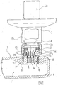
- FIG. 1 serves primarily to explain the environment in which the generally designated by the reference numeral 1 sanitary wall mixing fitting is used.
- a connector is shown, which has a substantially cylindrical shape and is located at its upper end portion 2a in the drawing in the assembled state within the mounting wall and there with the house line connected is.
- the connector 2 may be understood as part of the house line for purposes of the present description.
- the union nut 3 engages with a radially inwardly bent annular flange 3 a in a groove 2 c of the outer end portion 2 b of the connecting piece 2, so that it is rotatable relative to the connecting piece 2 but nevertheless axially fixed.
- a second connector is required, which is not shown in the drawing and at a certain distance, the "gauge", left to think of the illustrated connector 2.
- This gauge may vary somewhat from case to case, be it that the rules vary in different countries, either because the tradesman did not work exactly with the laying of the building services.
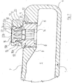
- FIGS. 1 and 2 illustrated end portion of the wall mixing fitting; the second end region and the adapter device provided there are formed symmetrically to a median plane of the wall mixing fitting 1 and need not be specifically described here.
- the sanitary wall mixing fitting 1 has a housing 4, which in the FIGS. 1 and 2 is shown cut. Within the housing 4, a water supply chamber 5 is recessed. From the water supply chamber 5, an internally threaded water inlet opening 6 leads to the rear wall 7 of the housing 2.
- an insert 8 is screwed, the in FIG. 3 is shown in perspective and a first part of the adapter device 50 represents.
- the insert 8 has a substantially cylindrical shape and on the lower portion of its outer circumferential surface an external thread 9, which cooperates with the thread of the water inlet opening 6.
- an annular groove 10 is provided in the lateral surface of the insert 8, which is particularly well in FIG. 2 can be seen.
- an O-ring 11 which seals the insert 8 against the lateral surface of the water inlet opening 6 in a thread-free area.
- a reduced diameter collar 12 is formed at the top of the insert 8 (which is actually the rear in the assembled state).
- the outer circumferential surface of the collar 12 carries an axially parallel toothing 13.
- the insert 8 is traversed by a water-conducting center bore 14 in operation, which is equipped with not provided with reference numerals key surfaces, which are helpful for screwing the insert 8 into the water inlet opening 6.
- an eccentric ring 15 is provided as a second part of the adapter device 50.
- the eccentric ring 5 has a bore 16 extending from its upper end to its lower end, which is composed of two regions 16a and 16b.
- the bottom in the drawing area 16a carries on its lateral surface an axially parallel internal toothing 17 which is complementary to the toothing 13 on the collar 12 of the insert 8. This means that the eccentric ring 15 in different angular positions, but then non-rotatable, can be plugged onto the insert 8.
- the upper portion 16b of the through hole 16 of the eccentric ring 15 in the drawing has a slightly larger diameter than the lower portion. Between the upper portion 16b and the lower portion 16a is a step 18.
- the axis of the through hole 16 is not in the axis of the eccentric ring 15 itself, but eccentric. This has the consequence that the axis of the eccentric ring 15 moves when the eccentric ring 15 is attached in different positions on the insert 8.
- FIG. 2 the position is shown in which the axis of the eccentric ring 15 occupies the rightmost position. In a rotation of the eccentric ring 15 by 180 °, this axis would occupy the leftmost position.
- the outer circumferential surface of the eccentric ring 15 carries an external thread 20 which cooperates with the internal thread of the union nut 3 in a known manner for fastening the connecting piece 2.
- FIG. 1 is for sealing purposes between the in FIG. 1 lower end of the connecting piece 2 and the upper Front side of the eccentric ring 15 a gasket 21 is provided.
- the eccentric ring 15 is fixed on the insert 8 by means of a screw 22, which also in perspective FIG. 3 drawn out and a third part of the adapter device 50 is.
- the screw member 22 is rotationally symmetrical and has an outwardly projecting flange 22a and an inner through hole 23 which is provided for screwing with key surfaces (without reference numerals).
- the lower, slightly reduced diameter portion 22b of the screw 22 carries an external thread 24th
- the eccentric ring 15 is first placed on the insert 8 in the desired position in which the correct gauge of the two connecting threads 20 is achieved. Then, the screw member 22 is inserted with the reduced diameter portion 22b ahead in the through hole 16 of the eccentric ring 15 and then screwed with its external thread 24 in an internal thread 25 which is formed on the inner circumferential surface of the collar 12 of the insert 8.
- the flange 22 a of the screw 22 abuts against the step 18 between the two areas 16 a, 16 b of the through hole of the eccentric ring 15 and presses the latter firmly against the annular surface on the top of the insert 8, which surrounds the collar 12.
- An O-ring 26 seals the eccentric ring 15 against the collar 8.
- FIG. 4 three components of the inventive embodiment of a sanitary wall-mixing fitting are shown, the in FIG. 3 represented and already described above components 8, 15 and 22 correspond.
- the components of the FIG. 4 have essentially the same function as the components of FIG. 3 and are therefore denoted by the same reference numeral plus 100.
Landscapes
- Health & Medical Sciences (AREA)
- Life Sciences & Earth Sciences (AREA)
- Engineering & Computer Science (AREA)
- Hydrology & Water Resources (AREA)
- Public Health (AREA)
- Water Supply & Treatment (AREA)
- Domestic Plumbing Installations (AREA)
Description
- Die Erfindung betrifft eine sanitäre Wand-Mischarmatur nach dem Oberbegriff des Patentanspruchs 1.
- Die wasserführenden Hausleitungen, an welche eine sanitäre Wand-Mischarmatur angeschlossen sind und über welche dieser Kalt- und Warmwasser zugeführt werden, sind in einem bestimmten Stichmaß aus der gebäudeseitigen Wand herausgeführt. Idealerweise stimmt dieses Stichmaß mit dem Stichmaß der Wasserzulauföffnungen an der Rückseite der sanitären Wand-Mischarmatur überein, so dass ein Anschluss direkt erfolgen kann.
- Die Situation wird für den Hersteller von Sanitärarmaturen jedoch dadurch kompliziert, dass in unterschiedlichen Ländern unterschiedliche Normen für das Stichmaß gelten. Während in Deutschland das Stichmaß 150 mm beträgt, ist dieses beispielsweise für die Schweiz 153 mm. Der zunächst naheliegende Gedanke, für die unterschiedlichen Länder unterschiedliche Armaturen mit unterschiedlichem Stichmaß der Wasserzulauföffnungen bereitzuhalten, verbietet sich, da hierdurch nicht nur die Herstellungskosten deutlich erhöht würden, sondern damit auch ein erheblicher Lager- und Logistikaufwand verbunden wäre.
- Dieser Problematik versucht die in der
DE 10 2009 012 109 B3 beschriebene sanitäre Wand-Mischarmatur, welche ähnlich derjenigen der eingangs genannten Art ist, zu begegnen. Hierzu wird an jeder Wasserzulauföffnung des Gehäuses eine Adaptereinrichtung eingesetzt. Diese ist mit einem Endbereich in der Wasserzulauföffnung des Gehäuses befestigt und weist einen außerhalb des Gehäuses liegenden kreiszylindrischen Bereich auf, der ein Anschlussgewinde zur Verbindung mit der Hausleitung besitzt. Die Achse dieses Anschlußgewindes ist gegenüber der Achse der Wasserzulauföffnung parallel versetzt. - Diese Adaptereinrichtung ist in der Wasserzulaufeinrichtung in einer solchen Winkelposition permanent befestigt, dass das gewünschte effektive Stichmaß der Anschlußgewinde erreicht wird, also beispielsweise bei Auslieferung in die Schweiz das Stichmaß von 153 mm, auch wenn das herstellerseitig vorgesehene Stichmass der Wasserzulauföffnungen der Wand-Mischarnatur nur 150 mm beträgt.
- Nachteilig bei dieser bekannten Wand-Mischarmatur ist, dass gleichwohl für unterschiedliche Länder unterschiedliche Sanitärarmaturen bereitgehalten werden müssen und dass Fehlverlegungen der Hausleitungen, die zu einem ungewünschten Abweichen des idealen Stichmaßes führen, auf andere Weise kompensiert werden müssen, beispielsweise durch herkömmliche S-Anschlüsse.
- Eine sanitäre Wand-Mischarmatur der eingangs genannten Art ist aus der
EP 2 327 841 A1 bekannt geworden. Zum Ausgleich unterschiedlicher Stichmaße zwischen den wasserführenden Wandleitungen und den Wasserzulauföffnungen der sanitären Wand-Mischarmatur ist dort vorgesehen, für jede Wasserzulauföffnung einen Satz von Verbindungsstücken bereitzustellen, die ineinander geschraubt werden, wobei mindestens eines der Verbindungsstücke einen Achsversatz derart aufweist, dass unterschiedliche Stichmaße ausgleichbar sind. Dabei unterscheidet diese Druckschrift zwei unterschiedliche Kopplungsarten, nämlch "rotary type coupling" und "prismatic type coupling". Letztere impliziert eine Verdrehsicherung, bedarf aber exakter Justierung auf das Stichmaß vor der Montage der Wand-Mischarmatur. In beiden Fällen werden die Verbindungsstücke mittels eines einschraubbaren Befestigungselements fixiert. - Auch eine aus der
DE 10 2007 007 408 A1 bekannte Wasserzulaufarmatur sieht Ausgleichselemente vor, welche sich exzentrisch verdrehen lassen und so einen Ausgleich in den Stichmaßen erlauben. Gleichzeitig gelingt es durch kugelgelenkige Übergänge an den Ausgleichselementen, eventuelle Schiefstellungen von Hausleitungen auszugleichen. - Aufgabe der vorliegenden Erfindung ist es, eine sanitäre Wand-Mischarmatur der eingangs genannten Art zu schaffen, welche im Einsatz flexibler ist.
- Diese Aufgabe wird erfindungsgemäß durch eine sanitäre Wand-Mischarmatur mit den im Patentanspruch 1 angegebenen Merkmalen gelöst.
- Wie aus der
EP 2 327 841 A1 an sich bekannt, wird also die Einstückigkeit der Adaptereinrichtung, die aus derDE 10 2009 012 109 B3 hervorgeht ist, aufgegeben. Ein gesonderter Exzenterring, der exzentrisch das zur Verbindung mit der Hausleitung dienende Anschlussgewinde trägt, kann nunmehr winkelmäßig gegenüber dem in der Wasserzulauföffnung des Gehäuses befestigten Einsatz nach Bedarf positioniert werden, so dass im Rahmen der Abstände, die zwischen den Achsen der Anschlussgewinde auf den Extenterringen und der Achsen der Wasserzulauföffnungen des Gehäuses bestehen, ein beliebiges Stichmaß der Anschlussgewinde eingestellt werden kann. Die Fixierung dieses gesonderten Exzenterringes an dem Einsatz in der gewünschten Winkelposition erfolgt mittels des Schraubteiles. - Schraubteil, Exzenterring und Einsatz weisen selbstverständlich entsprechende Kanäle auf, durch welche das Wasser strömen kann.
- Dabei weist der Einsatz eine Verzahnung auf, die zur Festlegung der relativen Winkelposition zwischen Exzenterring und Einsatz mit einer komplementären Verzahnung des Exzenterringes zusammenwirkt. Auf diese Weise lässt sich eine Vielzahl von relativen Winkelpositionen zwischen Exzenterring und Einsatz einstellen, die mit der Zahl der Zähne auf den komplementären Verzahnungen übereinstimmt.
- Die Verzahnungen von Einsatz und Exzenterring verlaufen achsparallel. Sie können auf diese Weise raumsparend untergebracht werden und gleichwohl eine erhebliche Länge besitzen, so dass die mechanische Stabilität groß ist.
- Erfindungsgemäß verlaufen die Verzahnungen von Einsatz und Exzenterring radial. Bei dieser Bauweise kann die radiale Abmessung der Adaptereinrichtung etwas kleiner gehalten werden; die mechanische Stabilität der Verbindung zwischen den Verzahnungen reicht gleichwohl im Allgemeinen gut aus.
- In einer Ausgestaltung der Erfindung ist es günstig, wenn die radial verlaufende Verzahnung des Einsatzes an einer stirnseitigen Ringfläche des Einsatzes ausgebildet ist, die radial innen von einem an den Einsatz angeformten Kragen kleineren Durchmessers begrenzt ist. Dieser Kragen dient der besseren Verbindung mit dem über ihn gestülpten Exzenterring.
- Schließlich ist es noch günstig, wenn der Einsatz der Adaptereinrichtung in die zugehörige WasserauslaufÖffnung eingeschraubt ist. Diese lösbare Verbindung gibt dem Hersteller der Sanitärarmatur größere Freiheit. So kann die Adaptereinrichtung der Sanitärarmatur je nach Einsatzort beigegeben werden oder auch nicht oder auch schon werkseitig montiert werden.
- Ein Ausführungsbeispiel der Erfindung wird nachfolgend anhand der Zeichnung näher erläutert, wobei zunächst das allgemeine, nicht durch die Ansprüche gedeckte Prinzip unter Bezug auf die
Figuren 1 bis 3 dargestellt wird. - Es zeigen
- Figur 1
- einen Anschlussbereich einer sanitären Wand-Mischarmatur, teilweise im Schnitt;
- Figur 2
- eine Teilvergrößerung aus
Figur 1 ; - Figur 3
- in einer Explosionsansicht beispielhaft drei Bauteile, die bei der Wand-Mischarmatur der
Figuren 1 und2 verwendet werden, welche jedoch nicht mit den erfindungsgemäßen Bauteilen über-einstimmen; - Figur 4
- eine Explosionsansicht, ähnlich der
Figur 3 , jedoch in der Ausführungsform der Erfindung; - Zunächst wird auf die
Figuren 1 bis 3 Bezug genommen. DieFigur 1 dient dabei in erster Linie der Erläuterung der Umgebung, in welcher die insgesamt mit dem Bezugszeichen 1 gekennzeichnete sanitäre Wand-Mischarmatur eingesetzt wird. Mit dem Bezugszeichen 2 ist ein Verbindungsstück dargestellt, das im Wesentlichen zylindrische Form besitzt und an seinem in der Zeichnung oberen Endbereich 2a im fertig montierten Zustand innerhalb der Montagewand liegt und dort mit der Hausleitung verbunden ist. Das Verbindungsstück 2 kann für die Zwecke der vorliegenden Beschreibung als Teil der Hausleitung verstanden werden. - Ein im Durchmesser etwas größerer Bereich 2b des Verbindungsstückes 2 ragt aus der Montagewand heraus und trägt an seinem äußeren, in
Figur 1 unteren Ende, eine Überwurfmutter 3, die in bekannter Weise der Verbindung mit der Wand-Mischarmatur 1 dient. Hierzu greift die Überwurfmutter 3 mit einem radial nach innen abgebogenen Ringflansch 3a in eine Nut 2c des äußeren Endbereiches 2b des Verbindungsstückes 2 ein, so dass sie gegenüber dem Verbindungsstück 2 verdrehbar aber gleichwohl axial festgelegt ist. - Zum vollständigen Anschluss der Wand-Mischarmatur 1 wird ein zweites Verbindungsstück benötigt, das in der Zeichnung nicht dargestellt ist und in einem bestimmten Abstand, dem "Stichmaß", links von dem dargestellten Verbindungsstück 2 zu denken ist. Dieses Stichmaß kann von Anwendungsfall zu Anwendungsfall etwas variieren, sei dies, dass die Vorschriften in den einzelnen Ländern unterschiedlich sind, sei dies, weil der Handwerker bei der Verlegung der Hausleitungen nicht exakt gearbeitet hat.
- Zur Bewältigung derartiger unterschiedlicher Stichmaße dienen zwei Adaptereinrichtungen 50. Beschrieben wird nachfolgend nur eine Adaptereinrichtung 50 in dem in den
Figuren 1 und2 dargestellte Endbereich der Wand-Mischarmatur; der zweite Endbereich und die dort vorgesehene Adaptereinrichtung sind symmetrisch zu einer Mittelebene der Wand-Mischarmatur 1 ausgebildet und brauchen hier nicht eigens beschrieben zu werden. - Die sanitäre Wand-Mischarmatur 1 besitzt ein Gehäuse 4, welches in den
Figuren 1 und2 geschnitten dargestellt ist. Innerhalb des Gehäuses 4 ist ein Wasserzulaufraum 5 ausgespart. Von dem Wasserzulaufraum 5 führt eine mit Innengewinde versehene Wasserzulauföffnung 6 zur Rückwand 7 des Gehäuses 2. - In die Wasserzulauföffnung 6 ist ein Einsatz 8 eingeschraubt, der in
Figur 3 perspektivisch herausgezeichnet ist und ein erstes Teil der Adaptereinrichtung 50 darstellt. Der Einsatz 8 besitzt im Wesentlichen zylindrische Form und auf dem unteren Bereich seiner Außenmantelfläche ein Außengewinde 9, welches mit dem Gewinde der Wasserzulauföffnung 6 zusammenwirkt. Oberhalb des Außengewindes 9 ist in der Mantelfläche des Einsatzes 8 eine Ringnut 10 vorgesehen, die besonders gut inFigur 2 zu erkennen ist. In der Ringnut 10 liegt ein O-Ring 11 ein, welcher den Einsatz 8 gegen die Mantelfläche der Wasserzulauföffnung 6 in einem gewindefreien Bereich abdichtet. - An die Oberseite des Einsatzes 8 (die in montiertem Zustand eigentlich die Hinterseite ist), ist ein im Durchmesser verringerter Kragen 12 angeformt. Die Außenmantelfläche des Kragens 12 trägt eine achsparallele Verzahnung 13.
- Der Einsatz 8 wird von einer im Betrieb wasserführenden Mittelbohrung 14 durchzogen, die mit nicht näher mit Bezugszeichen versehenen Schlüsselflächen ausgestattet ist, die zum Eindrehen des Einsatzes 8 in die Wasserzulauföffnung 6 behilflich sind.
- Über dem Einsatz 8 ist im montierten Zustand, der in den
Figuren 1 und2 dargestellt ist, ein Exzenterring 15 als zweites Teil der Adaptereinrichtung 50 vorgesehen. Der Exzenterring 5 besitzt eine von seiner oberen zur unteren Stirnseite durchgehende Bohrung 16, die aus zwei Bereichen 16a und 16b zusammengesetzt ist. Der in der Zeichnung untere Bereich 16a trägt an seiner Mantelfläche eine achsparallele Innenverzahnung 17, die komplementär zur Verzahnung 13 auf dem Kragen 12 des Einsatzes 8 ist. Dies bedeutet, dass der Exzenterring 15 in unterschiedlichen Winkelpositionen, dann jedoch unverdrehbar, auf den Einsatz 8 aufgesteckt werden kann. - Der in der Zeichnung obere Bereich 16b der Durchgangsbohrung 16 des Exzenterringes 15 besitzt einen etwas größeren Durchmesser als der untere Bereich. Zwischen dem oberen Bereich 16b und dem unteren Bereich 16a befindet sich eine Stufe 18.
- Wie insbesondere den
Figuren 2 und3 entnommen werden kann, verläuft die Achse der Durchgangsbohrung 16 nicht in der Achse des Exzenterringes 15 selbst, sondern exzentrisch. Dies hat zur Folge, dass die Achse des Exzenterringes 15 wandert, wenn der Exzenterring 15 in unterschiedlichen Positionen auf dem Einsatz 8 aufgesteckt ist. InFigur 2 ist diejenige Position dargestellt, in welcher die Achse des Exzenterringes 15 die am weitesten rechts liegende Position einnimmt. Bei einer Verdrehung des Exzenterringes 15 um 180° würde diese Achse die am weitesten links liegende Position einnehmen. - Die Außenmantelfläche des Exzenterringes 15 trägt ein Außengewinde 20, welches mit dem Innengewinde der Überwurfmutter 3 in bekannter Weise zur Befestigung des Verbindungsstückes 2 zusammenwirkt. Wie
Figur 1 zeigt, ist zu Dichtungszwecken zwischen dem inFigur 1 unteren Ende des Verbindungsstückes 2 und der oberen Stirnseite des Exzenterringes 15 eine Flachdichtung 21 vorgesehen. - Der Exzenterring 15 wird auf dem Einsatz 8 mit Hilfe eines Schraubteiles 22 festgelegt, das ebenfalls perspektivisch in
Figur 3 herausgezeichnet und ein drittes Teil der Adaptereinrichtung 50 ist. Das Schraubteil 22 ist rotationssymmetrisch und besitzt einen nach außen ragenden Flansch 22a sowie eine innere Durchgangsbohrung 23, die zum Einschrauben mit Schlüsselflächen (ohne Bezugszeichen) versehen ist. Der untere, im Durchmesser etwas verringerte Bereich 22b des Schraubteiles 22 trägt ein Außengewinde 24. - Zur Befestigung des Exzenterringes 15 an dem Einsatz 8 wird der Exzenterring 15 zunächst in der gewünschten Position, bei welcher das richtige Stichmaß der beiden Anschlußgewinde 20 erreicht wird, auf den Einsatz 8 aufgesteckt. Sodann wird das Schraubteil 22 mit dem im Durchmesser verringerten Bereich 22b voraus in die Durchgangsbohrung 16 des Exzenterringes 15 eingeführt und sodann mit seinem Außengewinde 24 in ein Innengewinde 25 eingeschraubt, welches an der Innenmantelfläche des Kragens 12 des Einsatzes 8 ausgebildet ist. Der Flansch 22a des Schraubteiles 22 legt sich an die Stufe 18 zwischen den beiden Bereichen 16a, 16b der Durchgangsbohrung des Exzenterringes 15 an und drückt letzteren fest gegen die Ringfläche an der Oberseite des Einsatzes 8, welche den Kragen 12 umgibt. Ein O-Ring 26 dichtet den Exzenterring 15 gegen den Kragen 8 ab.
- Nunmehr können mit den Überwurfmuttern 3 der Verbindungsstücke 2 die Verbindungen zwischen der Wand-Mischarmatur 1 und den Hausleitungen hergestellt werden.
- In
Figur 4 sind drei Bauelemente der erfindungsgemäßen Ausführungsform einer sanitären Wand-Mischarmatur dargestellt, die den inFigur 3 dargestellten und oben schon beschriebenen Bauteilen 8, 15 und 22 entsprechen. Die Bauteile derFigur 4 besitzen im Wesentlichen dieselbe Funktion wie die Bauteile derFigur 3 und sind daher mit demselben Bezugszeichen zuzüglich 100 gekennzeichnet. - Der einzige Unterschied, der zwischen den in den
Figuren 3 und4 dargestellten Ausführungsbeispielen besteht, ist die Position der zusammenwirkenden Verzahnungen an dem Exzenterring 15 bzw. 115 und dem Einsatz 8 bzw. 108. Während beim Ausführungsbeispiel gemäßFigur 3 die dem Exzenterring 15 zugeordnete Verzahnung eine achsparallele Innenverzahnung 17 an der Durchgangsbohrung 16 war, besitzt der Exzenterring 115 derFigur 4 eine radial verlaufende Verzahnung 117 an der unteren ringförmigen Stirnfläche. Der Einsatz 108 derFigur 4 trägt statt einer achsparallelen Außenverzahnung an dem Kragen 112 eine radiale Verzahnung 113 auf der Ringfläche an seiner Oberseite, die den Kragen 112 ergibt. Ersichtlich ist es auf diese Weise ebenfalls möglich, den Exzenterring 115 in unterschiedlichen Winkelpositionen auf dem Einsatz 108 aufzusetzen und mit dem Schraubteil 122 zu befestigen, das gegenüber dem ersten Ausführungsbeispiel unverändert geblieben ist.
Claims (3)
- Sanitäre Wand-Mischarmatur mita) einem Gehäuse (104), das an seiner Rückseite zwei Wasserzulauföffnungen (106) besitzt, deren parallele Achsen in einem bestimmten Stichmaß voneinander beabstandet sind;b) für jede Wasserzulauföffnung (106) einer Adaptereinrichtung (150), die an der zugehörigen Wasserzulauföffnung (106) befestigbar ist und ein Anschlussgewinde (120) zur Verbindung mit einer gebäudeseitigen Hausleitung besitzt und umfasst:dadurch gekennzeichnet, dassba) einen Einsatz (108), der in der Wasserzulauföffnung (106) des Gehäuses (104) befestigt ist;bb) einen Exzenterring (115), der an dem Einsatz (108) in unterschiedlichen Winkelstellungen befestigbar ist und der das Anschlussgewinde (120) trägt;bc) ein Schraubteil (122), welches sich durch den Exzenterring (115) hindurch erstreckt, an dem Einsatz (108) verschraubt ist und dadurch den Exzenterring (115) an dem Einsatz (108) fixiert;wobei der Einsatz (108) eine Verzahnung (113) aufweist, die zur Festlegung der relativen Winkelposition zwischen Exzenterring (115) und Einsatz (108) mit einer komplementären Verzahnung (117) des Exzenterrings (115) zusammenwirkt;
und wobei
die Achsen der Wasserzulauföffnung (106) des Gehäuses (104) und des Anschlussgewindes (120) parallel zueinander und voneinander beabstandet sind;c) die Verzahnungen (113, 117) von Einsatz (108) und Exzenterring (115) radial verlaufen. - Sanitäre Wand-Mischarmatur nach Anspruch 1, dadurch
gekennzeichnet, dass die radial verlaufende Verzahnung (113) des Einsatzes (108) an einer stirnseitigen Ringfläche des Einsatzes (108) ausgebildet ist, die radial innen von einem an den Einsatz (108) angeformten Kragen (112) kleineren Durchmessers begrenzt ist. - Sanitäre Wand-Mischarmatur nach Anspruch 1 oder 2,
dadurch gekennzeichnet, dass der Einsatz (108) der Adaptereinrichtung (150) in die zugehörige Wasserzulauföffnung (106) eingeschraubt ist.
Priority Applications (1)
| Application Number | Priority Date | Filing Date | Title |
|---|---|---|---|
| EP14002823.4A EP2816160B1 (de) | 2012-07-21 | 2013-07-06 | Wandarmatur mit einstellbarem Abstand der Anschlüsse |
Applications Claiming Priority (1)
| Application Number | Priority Date | Filing Date | Title |
|---|---|---|---|
| DE102012014705.8A DE102012014705A1 (de) | 2012-07-21 | 2012-07-21 | Sanitäre Wand-Mischarmatur |
Related Child Applications (2)
| Application Number | Title | Priority Date | Filing Date |
|---|---|---|---|
| EP14002823.4A Division-Into EP2816160B1 (de) | 2012-07-21 | 2013-07-06 | Wandarmatur mit einstellbarem Abstand der Anschlüsse |
| EP14002823.4A Division EP2816160B1 (de) | 2012-07-21 | 2013-07-06 | Wandarmatur mit einstellbarem Abstand der Anschlüsse |
Publications (2)
| Publication Number | Publication Date |
|---|---|
| EP2687640A1 EP2687640A1 (de) | 2014-01-22 |
| EP2687640B1 true EP2687640B1 (de) | 2016-05-11 |
Family
ID=48747886
Family Applications (2)
| Application Number | Title | Priority Date | Filing Date |
|---|---|---|---|
| EP14002823.4A Active EP2816160B1 (de) | 2012-07-21 | 2013-07-06 | Wandarmatur mit einstellbarem Abstand der Anschlüsse |
| EP13003420.0A Active EP2687640B1 (de) | 2012-07-21 | 2013-07-06 | Sanitäre Wand-Mischarmatur |
Family Applications Before (1)
| Application Number | Title | Priority Date | Filing Date |
|---|---|---|---|
| EP14002823.4A Active EP2816160B1 (de) | 2012-07-21 | 2013-07-06 | Wandarmatur mit einstellbarem Abstand der Anschlüsse |
Country Status (2)
| Country | Link |
|---|---|
| EP (2) | EP2816160B1 (de) |
| DE (1) | DE102012014705A1 (de) |
Families Citing this family (2)
| Publication number | Priority date | Publication date | Assignee | Title |
|---|---|---|---|---|
| FR3063752B1 (fr) * | 2017-03-08 | 2020-02-28 | Les Robinets Presto | Element de raccordement aux attentes murales d'un robinet mitigeur et ensemble comportant un robinet mitigeur et au moins un element de ce genre |
| DE102023104053A1 (de) * | 2023-02-17 | 2024-08-22 | Grohe Ag | Adapter zum Verbinden einer Sanitärarmatur mit einem S-Anschluss, Sanitärinstallation mit einem solchen Adapter sowie Verwendung eines Adapters |
Family Cites Families (6)
| Publication number | Priority date | Publication date | Assignee | Title |
|---|---|---|---|---|
| DE8703682U1 (de) * | 1987-03-12 | 1988-07-07 | Hans Grohe Gmbh & Co Kg, 7622 Schiltach | Einrichtung zum Befestigen einer Rosette an einem Mischventil |
| DE19527985A1 (de) * | 1995-07-31 | 1997-02-06 | Grohe Armaturen Friedrich | Mischbatterie |
| DE102007007408A1 (de) * | 2007-02-12 | 2008-08-14 | Sanchez, Leonardo | Wasserzulaufarmatur |
| DE102009012209B3 (de) | 2009-02-26 | 2010-02-25 | Kludi Gmbh & Co. Kg | Verfahren zum Herstellen einer Aufputz-Sanitärarmatur |
| DE102009012109B4 (de) | 2009-03-06 | 2011-05-12 | Siemens Aktiengesellschaft | Digitales Verfahren zur Kanalreduktion in MR Empfangs-Systemen und entsprechende Vorrichtung |
| EP2327841B1 (de) * | 2009-11-25 | 2015-05-27 | CRS S.p.A. | Bausatz für eine Mischbatterie, Mischbatterie und Montageverfahren einer Mischbatterie |
-
2012
- 2012-07-21 DE DE102012014705.8A patent/DE102012014705A1/de not_active Withdrawn
-
2013
- 2013-07-06 EP EP14002823.4A patent/EP2816160B1/de active Active
- 2013-07-06 EP EP13003420.0A patent/EP2687640B1/de active Active
Also Published As
| Publication number | Publication date |
|---|---|
| DE102012014705A1 (de) | 2014-01-23 |
| EP2816160B1 (de) | 2018-05-23 |
| EP2816160A1 (de) | 2014-12-24 |
| EP2687640A1 (de) | 2014-01-22 |
Similar Documents
| Publication | Publication Date | Title |
|---|---|---|
| EP1653141B1 (de) | Verbindungseinrichtung und Filtervorrichtung mit einer derartigen Verbindungseinrichtung | |
| DE102013205250B4 (de) | Rohranschlussadapter und Sanitärarmatur | |
| EP2778298B1 (de) | Sanitärarmaturen-Anschlusssystem | |
| EP2687640B1 (de) | Sanitäre Wand-Mischarmatur | |
| DE19529189C2 (de) | Anschlußstück | |
| DE2527132C3 (de) | Anschlußvorrichtung für einen Heizkörper | |
| EP0309397B2 (de) | Sanitäre Wasseranschlussanordnung | |
| DE102011082120B4 (de) | Anschlussblock | |
| DE3014368A1 (de) | Schalttafeleinbaugeraet zur einlochmontage in schalttafeln | |
| DE102012201693B4 (de) | Adapterelement | |
| DE202023002746U1 (de) | Schraubverbindung und Funktionsblock für Installationsanschluss | |
| DE102009011559A1 (de) | Sanitäre Unterputzarmatur | |
| EP0992632B1 (de) | Einrichtung zum Abdecken eines Wandanschlusses | |
| DE10138161C1 (de) | Befestigungsvorrichtung für ein zylindrisches Gerät | |
| EP4303371B1 (de) | Sanitärarmatur mit verriegelungselement | |
| EP1281939A1 (de) | Befestigungsring für einen Flüssigkeitszähler | |
| DE3826008A1 (de) | Sanitaere wasseranschlussanordnung | |
| DE102011076210B4 (de) | Befestigungsanordnung für zwei benachbarte Sanitärarmaturen | |
| EP0759487A1 (de) | Anschlussstück | |
| DE102007031741A1 (de) | Fluidverbindungsvorrichtung | |
| DE202015105273U1 (de) | Vorrichtung zum Anschluss von Auslaufarmaturen und Geräten und/oder Apparaten | |
| EP3711126B1 (de) | Winkelverschraubungssystem | |
| DE19652662C2 (de) | Sanitärschlauch | |
| DE202015100034U1 (de) | Hahnverlängerung zur Verbindung einer Wasserleitung mit einer Armatur | |
| DE102014203658A1 (de) | Hydraulisches Adaptermodul |
Legal Events
| Date | Code | Title | Description |
|---|---|---|---|
| PUAI | Public reference made under article 153(3) epc to a published international application that has entered the european phase |
Free format text: ORIGINAL CODE: 0009012 |
|
| AK | Designated contracting states |
Kind code of ref document: A1 Designated state(s): AL AT BE BG CH CY CZ DE DK EE ES FI FR GB GR HR HU IE IS IT LI LT LU LV MC MK MT NL NO PL PT RO RS SE SI SK SM TR |
|
| AX | Request for extension of the european patent |
Extension state: BA ME |
|
| 17P | Request for examination filed |
Effective date: 20140212 |
|
| RBV | Designated contracting states (corrected) |
Designated state(s): AL AT BE BG CH CY CZ DE DK EE ES FI FR GB GR HR HU IE IS IT LI LT LU LV MC MK MT NL NO PL PT RO RS SE SI SK SM TR |
|
| RAP1 | Party data changed (applicant data changed or rights of an application transferred) |
Owner name: HANSA ARMATUREN GMBH |
|
| GRAP | Despatch of communication of intention to grant a patent |
Free format text: ORIGINAL CODE: EPIDOSNIGR1 |
|
| INTG | Intention to grant announced |
Effective date: 20151204 |
|
| GRAS | Grant fee paid |
Free format text: ORIGINAL CODE: EPIDOSNIGR3 |
|
| GRAA | (expected) grant |
Free format text: ORIGINAL CODE: 0009210 |
|
| AK | Designated contracting states |
Kind code of ref document: B1 Designated state(s): AL AT BE BG CH CY CZ DE DK EE ES FI FR GB GR HR HU IE IS IT LI LT LU LV MC MK MT NL NO PL PT RO RS SE SI SK SM TR |
|
| REG | Reference to a national code |
Ref country code: GB Ref legal event code: FG4D Free format text: NOT ENGLISH |
|
| REG | Reference to a national code |
Ref country code: CH Ref legal event code: EP |
|
| REG | Reference to a national code |
Ref country code: AT Ref legal event code: REF Ref document number: 798797 Country of ref document: AT Kind code of ref document: T Effective date: 20160515 |
|
| REG | Reference to a national code |
Ref country code: IE Ref legal event code: FG4D Free format text: LANGUAGE OF EP DOCUMENT: GERMAN |
|
| REG | Reference to a national code |
Ref country code: CH Ref legal event code: NV Representative=s name: FREI PATENTANWALTSBUERO AG, CH |
|
| REG | Reference to a national code |
Ref country code: DE Ref legal event code: R096 Ref document number: 502013002936 Country of ref document: DE |
|
| REG | Reference to a national code |
Ref country code: SE Ref legal event code: TRGR |
|
| REG | Reference to a national code |
Ref country code: LT Ref legal event code: MG4D |
|
| REG | Reference to a national code |
Ref country code: NL Ref legal event code: MP Effective date: 20160511 |
|
| PG25 | Lapsed in a contracting state [announced via postgrant information from national office to epo] |
Ref country code: LT Free format text: LAPSE BECAUSE OF FAILURE TO SUBMIT A TRANSLATION OF THE DESCRIPTION OR TO PAY THE FEE WITHIN THE PRESCRIBED TIME-LIMIT Effective date: 20160511 Ref country code: NL Free format text: LAPSE BECAUSE OF FAILURE TO SUBMIT A TRANSLATION OF THE DESCRIPTION OR TO PAY THE FEE WITHIN THE PRESCRIBED TIME-LIMIT Effective date: 20160511 Ref country code: NO Free format text: LAPSE BECAUSE OF FAILURE TO SUBMIT A TRANSLATION OF THE DESCRIPTION OR TO PAY THE FEE WITHIN THE PRESCRIBED TIME-LIMIT Effective date: 20160811 |
|
| PG25 | Lapsed in a contracting state [announced via postgrant information from national office to epo] |
Ref country code: GR Free format text: LAPSE BECAUSE OF FAILURE TO SUBMIT A TRANSLATION OF THE DESCRIPTION OR TO PAY THE FEE WITHIN THE PRESCRIBED TIME-LIMIT Effective date: 20160812 Ref country code: ES Free format text: LAPSE BECAUSE OF FAILURE TO SUBMIT A TRANSLATION OF THE DESCRIPTION OR TO PAY THE FEE WITHIN THE PRESCRIBED TIME-LIMIT Effective date: 20160511 Ref country code: RS Free format text: LAPSE BECAUSE OF FAILURE TO SUBMIT A TRANSLATION OF THE DESCRIPTION OR TO PAY THE FEE WITHIN THE PRESCRIBED TIME-LIMIT Effective date: 20160511 Ref country code: PT Free format text: LAPSE BECAUSE OF FAILURE TO SUBMIT A TRANSLATION OF THE DESCRIPTION OR TO PAY THE FEE WITHIN THE PRESCRIBED TIME-LIMIT Effective date: 20160912 Ref country code: HR Free format text: LAPSE BECAUSE OF FAILURE TO SUBMIT A TRANSLATION OF THE DESCRIPTION OR TO PAY THE FEE WITHIN THE PRESCRIBED TIME-LIMIT Effective date: 20160511 Ref country code: LV Free format text: LAPSE BECAUSE OF FAILURE TO SUBMIT A TRANSLATION OF THE DESCRIPTION OR TO PAY THE FEE WITHIN THE PRESCRIBED TIME-LIMIT Effective date: 20160511 |
|
| PG25 | Lapsed in a contracting state [announced via postgrant information from national office to epo] |
Ref country code: IT Free format text: LAPSE BECAUSE OF FAILURE TO SUBMIT A TRANSLATION OF THE DESCRIPTION OR TO PAY THE FEE WITHIN THE PRESCRIBED TIME-LIMIT Effective date: 20160511 Ref country code: BE Free format text: LAPSE BECAUSE OF NON-PAYMENT OF DUE FEES Effective date: 20160731 |
|
| PG25 | Lapsed in a contracting state [announced via postgrant information from national office to epo] |
Ref country code: CZ Free format text: LAPSE BECAUSE OF FAILURE TO SUBMIT A TRANSLATION OF THE DESCRIPTION OR TO PAY THE FEE WITHIN THE PRESCRIBED TIME-LIMIT Effective date: 20160511 Ref country code: SK Free format text: LAPSE BECAUSE OF FAILURE TO SUBMIT A TRANSLATION OF THE DESCRIPTION OR TO PAY THE FEE WITHIN THE PRESCRIBED TIME-LIMIT Effective date: 20160511 Ref country code: RO Free format text: LAPSE BECAUSE OF FAILURE TO SUBMIT A TRANSLATION OF THE DESCRIPTION OR TO PAY THE FEE WITHIN THE PRESCRIBED TIME-LIMIT Effective date: 20160511 Ref country code: EE Free format text: LAPSE BECAUSE OF FAILURE TO SUBMIT A TRANSLATION OF THE DESCRIPTION OR TO PAY THE FEE WITHIN THE PRESCRIBED TIME-LIMIT Effective date: 20160511 Ref country code: DK Free format text: LAPSE BECAUSE OF FAILURE TO SUBMIT A TRANSLATION OF THE DESCRIPTION OR TO PAY THE FEE WITHIN THE PRESCRIBED TIME-LIMIT Effective date: 20160511 |
|
| REG | Reference to a national code |
Ref country code: DE Ref legal event code: R097 Ref document number: 502013002936 Country of ref document: DE |
|
| PG25 | Lapsed in a contracting state [announced via postgrant information from national office to epo] |
Ref country code: SM Free format text: LAPSE BECAUSE OF FAILURE TO SUBMIT A TRANSLATION OF THE DESCRIPTION OR TO PAY THE FEE WITHIN THE PRESCRIBED TIME-LIMIT Effective date: 20160511 Ref country code: PL Free format text: LAPSE BECAUSE OF FAILURE TO SUBMIT A TRANSLATION OF THE DESCRIPTION OR TO PAY THE FEE WITHIN THE PRESCRIBED TIME-LIMIT Effective date: 20160511 |
|
| PLBE | No opposition filed within time limit |
Free format text: ORIGINAL CODE: 0009261 |
|
| STAA | Information on the status of an ep patent application or granted ep patent |
Free format text: STATUS: NO OPPOSITION FILED WITHIN TIME LIMIT |
|
| PG25 | Lapsed in a contracting state [announced via postgrant information from national office to epo] |
Ref country code: MC Free format text: LAPSE BECAUSE OF FAILURE TO SUBMIT A TRANSLATION OF THE DESCRIPTION OR TO PAY THE FEE WITHIN THE PRESCRIBED TIME-LIMIT Effective date: 20160511 |
|
| 26N | No opposition filed |
Effective date: 20170214 |
|
| PG25 | Lapsed in a contracting state [announced via postgrant information from national office to epo] |
Ref country code: FR Free format text: LAPSE BECAUSE OF NON-PAYMENT OF DUE FEES Effective date: 20160801 |
|
| REG | Reference to a national code |
Ref country code: FR Ref legal event code: ST Effective date: 20170331 |
|
| REG | Reference to a national code |
Ref country code: IE Ref legal event code: MM4A |
|
| PG25 | Lapsed in a contracting state [announced via postgrant information from national office to epo] |
Ref country code: SI Free format text: LAPSE BECAUSE OF FAILURE TO SUBMIT A TRANSLATION OF THE DESCRIPTION OR TO PAY THE FEE WITHIN THE PRESCRIBED TIME-LIMIT Effective date: 20160511 |
|
| PG25 | Lapsed in a contracting state [announced via postgrant information from national office to epo] |
Ref country code: IE Free format text: LAPSE BECAUSE OF NON-PAYMENT OF DUE FEES Effective date: 20160706 |
|
| PG25 | Lapsed in a contracting state [announced via postgrant information from national office to epo] |
Ref country code: LU Free format text: LAPSE BECAUSE OF NON-PAYMENT OF DUE FEES Effective date: 20160706 |
|
| GBPC | Gb: european patent ceased through non-payment of renewal fee |
Effective date: 20170706 |
|
| PG25 | Lapsed in a contracting state [announced via postgrant information from national office to epo] |
Ref country code: GB Free format text: LAPSE BECAUSE OF NON-PAYMENT OF DUE FEES Effective date: 20170706 |
|
| PG25 | Lapsed in a contracting state [announced via postgrant information from national office to epo] |
Ref country code: CY Free format text: LAPSE BECAUSE OF FAILURE TO SUBMIT A TRANSLATION OF THE DESCRIPTION OR TO PAY THE FEE WITHIN THE PRESCRIBED TIME-LIMIT Effective date: 20160511 Ref country code: HU Free format text: LAPSE BECAUSE OF FAILURE TO SUBMIT A TRANSLATION OF THE DESCRIPTION OR TO PAY THE FEE WITHIN THE PRESCRIBED TIME-LIMIT; INVALID AB INITIO Effective date: 20130706 |
|
| PG25 | Lapsed in a contracting state [announced via postgrant information from national office to epo] |
Ref country code: MK Free format text: LAPSE BECAUSE OF FAILURE TO SUBMIT A TRANSLATION OF THE DESCRIPTION OR TO PAY THE FEE WITHIN THE PRESCRIBED TIME-LIMIT Effective date: 20160511 Ref country code: TR Free format text: LAPSE BECAUSE OF FAILURE TO SUBMIT A TRANSLATION OF THE DESCRIPTION OR TO PAY THE FEE WITHIN THE PRESCRIBED TIME-LIMIT Effective date: 20160511 Ref country code: IS Free format text: LAPSE BECAUSE OF FAILURE TO SUBMIT A TRANSLATION OF THE DESCRIPTION OR TO PAY THE FEE WITHIN THE PRESCRIBED TIME-LIMIT Effective date: 20160511 Ref country code: MT Free format text: LAPSE BECAUSE OF FAILURE TO SUBMIT A TRANSLATION OF THE DESCRIPTION OR TO PAY THE FEE WITHIN THE PRESCRIBED TIME-LIMIT Effective date: 20160511 |
|
| PG25 | Lapsed in a contracting state [announced via postgrant information from national office to epo] |
Ref country code: BG Free format text: LAPSE BECAUSE OF FAILURE TO SUBMIT A TRANSLATION OF THE DESCRIPTION OR TO PAY THE FEE WITHIN THE PRESCRIBED TIME-LIMIT Effective date: 20160511 |
|
| PG25 | Lapsed in a contracting state [announced via postgrant information from national office to epo] |
Ref country code: AL Free format text: LAPSE BECAUSE OF FAILURE TO SUBMIT A TRANSLATION OF THE DESCRIPTION OR TO PAY THE FEE WITHIN THE PRESCRIBED TIME-LIMIT Effective date: 20160511 |
|
| REG | Reference to a national code |
Ref country code: CH Ref legal event code: PCAR Free format text: NEW ADDRESS: POSTFACH, 8032 ZUERICH (CH) |
|
| PGFP | Annual fee paid to national office [announced via postgrant information from national office to epo] |
Ref country code: SE Payment date: 20220720 Year of fee payment: 10 Ref country code: FI Payment date: 20220721 Year of fee payment: 10 Ref country code: AT Payment date: 20220721 Year of fee payment: 10 |
|
| PGFP | Annual fee paid to national office [announced via postgrant information from national office to epo] |
Ref country code: CH Payment date: 20220725 Year of fee payment: 10 |
|
| P01 | Opt-out of the competence of the unified patent court (upc) registered |
Effective date: 20230513 |
|
| REG | Reference to a national code |
Ref country code: CH Ref legal event code: PL |
|
| REG | Reference to a national code |
Ref country code: SE Ref legal event code: EUG |
|
| REG | Reference to a national code |
Ref country code: AT Ref legal event code: MM01 Ref document number: 798797 Country of ref document: AT Kind code of ref document: T Effective date: 20230706 |
|
| PG25 | Lapsed in a contracting state [announced via postgrant information from national office to epo] |
Ref country code: AT Free format text: LAPSE BECAUSE OF NON-PAYMENT OF DUE FEES Effective date: 20230706 |
|
| PG25 | Lapsed in a contracting state [announced via postgrant information from national office to epo] |
Ref country code: FI Free format text: LAPSE BECAUSE OF NON-PAYMENT OF DUE FEES Effective date: 20230706 Ref country code: AT Free format text: LAPSE BECAUSE OF NON-PAYMENT OF DUE FEES Effective date: 20230706 Ref country code: CH Free format text: LAPSE BECAUSE OF NON-PAYMENT OF DUE FEES Effective date: 20230731 |
|
| PG25 | Lapsed in a contracting state [announced via postgrant information from national office to epo] |
Ref country code: SE Free format text: LAPSE BECAUSE OF NON-PAYMENT OF DUE FEES Effective date: 20230707 |
|
| PGFP | Annual fee paid to national office [announced via postgrant information from national office to epo] |
Ref country code: DE Payment date: 20250723 Year of fee payment: 13 |