EP2687660B1 - Charnière - Google Patents
Charnière Download PDFInfo
- Publication number
- EP2687660B1 EP2687660B1 EP13003620.5A EP13003620A EP2687660B1 EP 2687660 B1 EP2687660 B1 EP 2687660B1 EP 13003620 A EP13003620 A EP 13003620A EP 2687660 B1 EP2687660 B1 EP 2687660B1
- Authority
- EP
- European Patent Office
- Prior art keywords
- door
- fitments
- adjusting
- hinge
- adjusting device
- Prior art date
- Legal status (The legal status is an assumption and is not a legal conclusion. Google has not performed a legal analysis and makes no representation as to the accuracy of the status listed.)
- Active
Links
Images




Classifications
-
- E—FIXED CONSTRUCTIONS
- E05—LOCKS; KEYS; WINDOW OR DOOR FITTINGS; SAFES
- E05D—HINGES OR SUSPENSION DEVICES FOR DOORS, WINDOWS OR WINGS
- E05D3/00—Hinges with pins
- E05D3/02—Hinges with pins with one pin
- E05D3/022—Hinges with pins with one pin allowing an additional lateral movement, e.g. for sealing
-
- E—FIXED CONSTRUCTIONS
- E05—LOCKS; KEYS; WINDOW OR DOOR FITTINGS; SAFES
- E05F—DEVICES FOR MOVING WINGS INTO OPEN OR CLOSED POSITION; CHECKS FOR WINGS; WING FITTINGS NOT OTHERWISE PROVIDED FOR, CONCERNED WITH THE FUNCTIONING OF THE WING
- E05F1/00—Closers or openers for wings, not otherwise provided for in this subclass
- E05F1/02—Closers or openers for wings, not otherwise provided for in this subclass gravity-actuated, e.g. by use of counterweights
- E05F1/04—Closers or openers for wings, not otherwise provided for in this subclass gravity-actuated, e.g. by use of counterweights for wings which lift during movement, operated by their own weight
- E05F1/06—Mechanisms in the shape of hinges or pivots, operated by the weight of the wing
-
- E—FIXED CONSTRUCTIONS
- E05—LOCKS; KEYS; WINDOW OR DOOR FITTINGS; SAFES
- E05Y—INDEXING SCHEME ASSOCIATED WITH SUBCLASSES E05D AND E05F, RELATING TO CONSTRUCTION ELEMENTS, ELECTRIC CONTROL, POWER SUPPLY, POWER SIGNAL OR TRANSMISSION, USER INTERFACES, MOUNTING OR COUPLING, DETAILS, ACCESSORIES, AUXILIARY OPERATIONS NOT OTHERWISE PROVIDED FOR, APPLICATION THEREOF
- E05Y2201/00—Constructional elements; Accessories therefor
- E05Y2201/60—Suspension or transmission members; Accessories therefor
- E05Y2201/622—Suspension or transmission members elements
- E05Y2201/638—Cams; Ramps
-
- E—FIXED CONSTRUCTIONS
- E05—LOCKS; KEYS; WINDOW OR DOOR FITTINGS; SAFES
- E05Y—INDEXING SCHEME ASSOCIATED WITH SUBCLASSES E05D AND E05F, RELATING TO CONSTRUCTION ELEMENTS, ELECTRIC CONTROL, POWER SUPPLY, POWER SIGNAL OR TRANSMISSION, USER INTERFACES, MOUNTING OR COUPLING, DETAILS, ACCESSORIES, AUXILIARY OPERATIONS NOT OTHERWISE PROVIDED FOR, APPLICATION THEREOF
- E05Y2900/00—Application of doors, windows, wings or fittings thereof
- E05Y2900/10—Application of doors, windows, wings or fittings thereof for buildings or parts thereof
- E05Y2900/114—Application of doors, windows, wings or fittings thereof for buildings or parts thereof for showers
Definitions
- the invention relates to a hinge for pivoting a door, in particular for the door of a shower enclosure, with the features of the preamble of claim 1 and a shower enclosure with at least one such hinge.
- Such hinges for pivoting a door relative to a wall are already known from the prior art. So shows about the AT 010 648 U1 of 15 July 2009 a door hinge with a lifting and lowering mechanism. By this lifting-lowering mechanism, the door is raised during the pivoting operation or lowers during the closing process, whereby the shower enclosure is sealed.
- an arcuate ramp is formed in the hinge, on which a driving element of the hinge moves and thus the door is raised or lowered.
- it is disadvantageous that can deposit dirt on the arcuate ramp, which is very difficult to remove and that the sealing effect is small when the door is closed.
- the object of the invention is to provide a comparison with the prior art improved hinge for a shower enclosure, which u. a. a better sealing effect of the shower enclosure causes.
- the hinge has at least two fittings, which are connected to one another via a pivot pin, wherein one of the fittings is designed as a door fitting and another fitting as a counter fitting.
- the two fittings are connected to form a gap having a gap width via a rotary joint pivotable about an axis of rotation.
- the hinge has an adjusting device, wherein the adjusting device has at least one adjusting contour and at least one adjusting element, wherein the at least one adjusting element is supported on the one hand on the at least one adjusting contour and on the other hand on one of the two fittings.
- the pivot pin is rotatably formed on the door fitting, wherein the adjusting contour is formed on the pivot pin and wherein the pivot pin is connected via a driving element with the counter fitting and causes an adjustment of the two fittings along a direction parallel to the axis of rotation.
- the adjusting device further comprises a guide, wherein the guide has a section formed as a ramp with an inclined plane on which the driving element is substantially rectilinear, whereby a method of the driving element along the section a combined movement of the two fittings to each other at right angles to and causes along the axis of rotation and further causes the pivoting of the door and an adjustment of the two fittings relative to each other in a direction perpendicular to the axis of rotation, changing the gap width.
- the adjusting contour and / or the driving element are designed such that the pivoting of the two fittings on the hinge over a portion of the pivoting range only causes an adjustment of the two fittings relative to each other in a direction perpendicular to the axis of rotation and the Pivoting the two fittings over another part of the pivoting range causes only an adjustment of the two fittings relative to each other in the direction of the axis of rotation.
- the inclined plane of the ramp in installation position extends substantially parallel to the wall or substantially parallel to the door.
- the driving element slides on the inclined plane.
- the fact that the driving element slides on the inclined plane can be dispensed with roles or wheels. It is of course also conceivable that rollers are used to reduce the friction occurring.
- pivot pin it has also proven to be advantageous for the pivot pin to have, at least in regions, a cross-section deviating from the circular shape.
- the actuating element is bolt-shaped.
- the adjusting device has a setting device for adjusting the stroke of the door, so that the door relative to the wall or to a shower tray in particular horizontally adjustable both in angle and in the distance, wherein the adjusting device has at least one adjustment, the with the Adjusting element corresponds, wherein the adjusting element is applied to the actuating element.
- the adjusting device has at least two adjusting elements, wherein the adjusting elements are supported on the one hand on the adjusting contour and on the other hand on one of the two fittings.
- the two adjusting elements are arranged parallel to each other.
- the adjusting device has at least two adjusting elements which correspond to the two adjusting elements, wherein the two adjusting elements bear against the two adjusting elements.
- the door of the shower enclosure can be preferably aligned.
- At least one energy accumulator is provided with variable memory content and that the memory contents of the at least one energy accumulator can be changed by pivoting the at least two fittings about the pivot.
- a particularly advantageous structural variant provides that the at least one energy accumulator supports the adjustment of the two fittings in the direction parallel to the axis of rotation.
- the at least one Power storage supports a provision of at least two fittings in the zero position.
- the at least one energy accumulator supports a pivoting of the at least two fittings from the predetermined zero position.
- At least two energy accumulators are provided, of which at least one energy storage assisted by the at least two fittings from the predetermined zero position, the provision of at least two fittings in the zero position and another of the at least two energy storage, the pivoting of at least supports two fittings from the predetermined zero position.
- the at least one energy accumulator has a longitudinal extent which runs essentially parallel to the axis of rotation.
- the at least one energy accumulator is designed as a spring.
- the spring is designed as a helical spring.
- the spring is designed as a compression spring.
- Protection is also desired for a shower enclosure with at least one hinge - preferably with at least two hinges - for pivoting a door relative to a wall according to at least one of the described embodiments.
- the shower enclosure has at least one sealing lip between the door and the wall, wherein by pivoting the door in a closed state of the door, the sealing lip between the door and the wall can be pressed. As a result, the sealing effect between the door and the wall can be increased when the door is closed.
- the driving element is designed as a gear and the adjusting contour has a first portion which is perpendicular to the axis of rotation, wherein the gear on the first portion is movable up to a stop and the adjusting contour has a second portion which movement allowed in the direction of the axis of rotation, wherein on one side of the gear, a lifting-lowering device is arranged, which causes after the detection of the gear on the stop an adjustment of the two fittings along the second portion in a direction parallel to the axis of rotation.
- the driving element is again formed as a gear and the adjusting device has at least two control contours, wherein the first adjusting contour is perpendicular to the axis of rotation, wherein the gear along the first control contour is moved to a stop and the second control contour movement allowed in the direction of the axis of rotation, wherein on one side of the gear, a lifting-lowering device is arranged, which causes after the determination of the gear on the stop an adjustment of the two fittings along the second setting contour in a direction parallel to the axis of rotation.
- those parts of the adjusting device 70, which cause the adjustment of the fittings 10, 20 along a direction parallel to the rotation axis 31 are also summarized under the term "lifting-lowering device 30" and those parts of the adjusting device 70, which Adjustment of the fittings 10, 20 in a direction perpendicular to the axis of rotation 31 effect, also summarized under the term "lifting device 40".
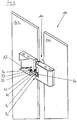
- FIG. 1 shows a perspective view of a shower enclosure 110, wherein the shower enclosure 110 has a wall 102 and a door 101. Via the hinge 100, the wall 102 is connected to the door 101.
- the hinge 100 consists of a fitting 10, which is designed as a door fitting 11 and is fixed to the door 101, and on the other hand from the fitting 20, which is designed as a counter fitting 21.
- the counter fitting 21 is normally attached to either a wall 102 or a fixed part 102 of the shower enclosure 110.
- the two fittings 10 and 20 are hingedly connected to each other via a pivot pin 4.
- the two fittings 10 and 20 are connected to form a column width 33 having gap 32 via the rotary joint 34 about a rotation axis 31 pivotally connected to each other.
- the door 101 via the hinge 100, the door 101 can be pivoted both into the interior of the shower enclosure 101 and into the outside space.
- the pivot pin 4 is rotatably formed on the door fitting 11 and connected via the driving element 2 with the counter fitting 21.
- the counter fitting 21 has a cover 22, which in the FIG. 2 was removed to gain insight into the interior of the hinge.
- FIG. 2 shows a hinge 100 for pivoting a door 101, wherein in this embodiment it is the door 101 of a shower enclosure 110.
- the two fittings 10 and 20 are pivotally connected to each other via a rotary joint 34 about a rotation axis 31 and form a gap 32, which has a gap width 33 - the gap width between the wall 102 and the door 101. Furthermore, the hinge 100 has an adjusting device 70th for the two fittings 10 and 20 on.
- a pivoting of the two fittings 10 and 20 via the rotary joint 34 leads to an adjustment of the two fittings 10 and 20 to each other.
- the pivoting of the two fittings 10 and 20 via the pivot 34 causes both an adjustment of the two fittings 10 and 20 relative to each other in a direction perpendicularly changing the gap width 33 to the axis of rotation 31 and in the direction of the axis of rotation 31st
- the driving element 2 of the fitting 20 can move on the ramp 1, wherein the ramp 1 has an inclined plane 3, on which the driving element 2 moves.
- the adjusting device 70 in this case has the guide 5 for the driving element 2, wherein the guide 5 has a portion which is formed so that a method of the driving element 2 along the portion of a combined movement of the two fittings 10 and 20 to each other at right angles to and along the axis of rotation 31 causes.
- the door 101 is raised on the one hand and on the other hand removed from the wall 102. It is the Section designed as a ramp 1 with an inclined plane 3, on which the driving element 2 is substantially rectilinearly movable.
- the driving element 2 functions in this embodiment as a hinge arm of the hinge 100 and is also integrally formed.
- the ramp 1 is formed on the counter fitting 21. Likewise, it is also conceivable to form the ramp 1 on the door fitting 11.
- the inclined plane 3 of the ramp 1 is formed substantially parallel to the wall 102 of the shower enclosure 110.
- the driving element 2 is formed in this preferred embodiment without wheels or rollers and slides only on the inclined plane 3 of the ramp 1 there. It is also conceivable, of course, for rollers to be used as a driving element 2 in order to reduce the friction occurring between the driving element 2 and the inclined plane 3 of the ramp 1. Thus, for example, it is envisaged to form the guide 5 with the driving element 2 as a slide bearing, which is thus movable under extremely low friction on the inclined plane 3 of the ramp 1.
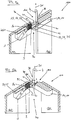
- FIG. 3 shows a perspective view of the hinge 100 of the shower enclosure 110, wherein in the hinge 100 for reasons of clarity, the driving element 2 is not shown.
- the ramp 1 and its inclined plane 3 is clearly visible, it being easy to read from this perspective, in particular, that the inclined plane 3 runs parallel to the wall 102.
- the inclined plane 3 and its ramp 1 would be formed on the door fitting 11 and thus would then run the inclined plane 3 of the ramp 1 parallel to the wall 102.
- the adjusting device 70 has a setting contour 41 and the adjusting elements 42 and 43, wherein the adjusting elements 42 and 43 are supported on the one hand on the adjusting contour 41 and on the other hand on one of the two fittings 10 and 20, so that it on Pivoting the door 101 to a horizontal offset of the door 101 comes.
- the pivot pin 4 has a deviating from the circular cross-section, whereby thus the adjusting contour 41 is formed on the pivot pin 4.
- the pivot pin 4 is rotatably formed on the door fitting 11 and the ramp 1 - as already mentioned - formed on counter fitting 21, wherein the adjusting elements 42 and 43 are supported on the one hand on the counter fitting 21 and on the other hand supported on the adjusting contour 41 on the pivot pin 4.
- FIG. 4 shows a perspective view of the hinge 100 of the shower enclosure 110th
- a setting device 50 is further formed for the adjusting device 70, with which the stroke of the door 101 are adjusted can, wherein the adjusting device 50 has the two adjusting elements 52 and 53, which correspond to the adjusting elements 42 and 43 of the lifting device 40, wherein the two adjusting elements 52 and 53 abut the adjusting elements 42 and 43.
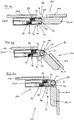
- FIGS. 5a and 5b are sectional views in perspective of the hinge 100 of the shower enclosure 110 shown in different door positions.
- the hinge 100 is particularly well on the one hand, the lifting device 40 and on the other hand, the adjustment device 50 and its operation recognizable.
- the two adjusting elements 42 and 43 correspond to the two adjusting elements 52 and 53 of the adjusting device 50.
- the adjusting elements 52 and 53 of the adjusting device 50 as a screw 54 - taken exactly as grub screw 55 -.
- the adjusting device 50 By means of the adjusting device 50, it is also still possible to align the door 101 after mounting already carried out on a shower tray, not shown. For this purpose, one adjusts the adjusting elements 52 and 53 of the adjusting device 50 unevenly, that is, a grub screw 55 is screwed in or screwed in a different extent than the second grub screw 55 of the adjusting device 50. This results in a change in the angle of the door 101 relative to Wall 102 of the shower enclosure 110.
- the door 101 can also be subsequently aligned after installation of the shower enclosure 110, without doing something on the hinge 100 or on the shower enclosure 110 would have to be dismantled - apart from the cover 22 (see FIG. 1 ).
- the two adjusting elements 42 and 43 of the lifting device 40 are based on the control contour 41 of the pivot pin 4.
- the pivot pin 4 is rotatably formed in the door fitting 11. When pivoting the door 101 of the Door fitting 11 mitverschwenkt. The fact that the pivot pin 4 is rotatably formed with respect to the door fitting 11, this is also mitverschwenkt.
- the adjusting contour 41 on the pivot pin 4 now acts on the two adjusting elements 42 and 43 of the lifting device 40, whereby - as in FIG. 5b shown - the door 101 is pushed further away from the wall 102, since the actuating contour 41 in this position has a greater distance from the central axis of the pivot pin 4.
- the adjusting elements 42 and 43 are preferably formed bolt-shaped and are arranged parallel to each other. Thus, a simple alignment of the door 101 to the wall 102 is made possible.
- FIGS. 6a to 6c is again shown in three different positions, the pivoting of a door 101 of a shower enclosure 110 relative to a wall 102.
- FIGS. 7a and 7b is now a non-inventive variant of a door hinge 100 shown, in which the vertical offset and the horizontal offset is not the same time when pivoting the fittings 10 and 20 of the door hinge 100, but at the first horizontal offset occurs and then - after completion of the horizontal offset - the vertical offset is performed.
- the driving element 2 is formed as a toothed wheel 60 which is linearly movable along a toothed rack - the setting contour 141 - in the fitting 20 until it abuts a stop 61 in the fitting 20. Subsequently, the lifting-lowering device 30 is used and the fitting 10 is raised via the adjusting contour 41 at the pivot 34.
- the actuating contours 41 and 141 and the driving element 2 are thus designed such that the pivoting of the two fittings 10 and 20 via the pivot 34 over a portion of the pivoting range only one adjustment of the two fittings 10 and 20 relative to each other in a direction perpendicular to the axis of rotation 31st causes and the pivoting of the two fittings 10 and 20 via another part of the pivoting range only an adjustment of the two fittings 10 and 20 relative to each other in the direction of the axis of rotation 31 causes.
- a pivoting of the two fittings 10 and 20 via the pivot 34 also leads in this embodiment to an adjustment of the two fittings 10 and 20 to each other.
- the pivoting of the two fittings 10 and 20 via the pivot 34 causes both an adjustment of the two fittings 10 and 20 relative to each other in a direction perpendicularly changing the gap width 33 to the axis of rotation 31 and in the direction of the axis of rotation 31st
- the adjusting device 70 has two setting contours 41 and 141, wherein the driving element 2 designed as a gear 60 along the first actuating contour 141 - which is designed as a rack and perpendicular to the axis of rotation 31 - moves up to the stop 61. Furthermore, a second control contour 41 is provided, which has a portion which allows movement in the direction of the axis of rotation 31, wherein on one side of the gear 60, a raising-lowering device 30 is arranged, which after the detection of the gear 60 at the stop 61st an adjustment of the two fittings 10 and 20 along the portion of the second adjusting contour 41 in a direction parallel to the axis of rotation 31 causes.
- FIGS. 8a to 9b another variant of a door hinge 100 not according to the invention is shown, in which there is a horizontal and vertical offset of the two fittings 10 and 20 to each other when pivoting the two fittings 10 and 20 to each other.
- the vertical and horizontal offset again takes place simultaneously, as in the embodiment of FIGS. 1 to 6c .
- This hinge 100 likewise has, in turn, an adjusting device 70 which has two setting contours 41 and 141, setting contour 41 for the vertical offset and the setting contour 141 for the horizontal offset of the fitting 20 for fitting 10.
- the two fittings 10 and 20 are aligned substantially in a plane to each other and the driving element 2 is located close to the pivot 34 and its axis of rotation 31.
- the driving element. 2 of the fitting 20 is pressed against the setting contour 141 of the adjusting device 70.
- the hinge 100 has a lifting-lowering device 30, which has the adjusting contour 41, via which the fitting 20 can be raised or lowered relative to the fitting 10.
- the fitting 20 is in the lowered position. This corresponds to the closed state of the shower enclosure 110, not shown here.
- FIGS. 9a and 9b now show an opening state of the hinge 100, wherein it should be noted that the representation of the hinge 100 is shown rotated by 90 ° counterclockwise, compared to the representation of FIGS. 8a and 8b ,
- the driving element 2 along the control contour 141 of the actuator 70 was pushed horizontally away from the pivot 34 and the axis of rotation 31 and against the spring force of the spring of the spring device 23 of the fitting 20th
- the temporal sequence could also be controlled in reverse, first the vertical movement and then the horizontal movement. This would be advantageous, for example, if a surge protection strip is mounted on the floor. Then the door would first be lifted before it is pivoted so as not to run over the splash guard strip - for example with the lower edge of the door or a draining rubber mounted on the lower edge of the door.
- a pivoting of the two fittings 10 and 20 via the pivot 34 also leads in this third embodiment to an adjustment of the two fittings 10 and 20 to each other.
- the pivoting of the two fittings 10 and 20 via the pivot 34 causes both an adjustment of the two fittings 10 and 20 relative to each other in a direction perpendicularly changing the gap width 33 to the axis of rotation 31 and in the direction of the axis of rotation 31st
- FIG. 10 shows a perspective view of a shower enclosure 110, in which between the wall 102 and the door 101, two hinges 100 are formed.
- the door 101 is pivoted relative to the wall 102, wherein it comes to a horizontal and vertical displacement of the door 101 relative to the wall 102 of the shower enclosure 110 during the pivoting operation.
- a sealing lip is formed between the door 101 and the wall 102 in order to seal the shower partition 110 in the closed state of the door 101, whereby no water can escape from the interior of the shower enclosure 110.
- On the representation of the sealing lip was in this FIG. 10 omitted, since it is an already known, belonging to the state of the art sealing lip.
- the sealing lip between the door 101 and the wall 102 can be pressed - and to a much greater extent than in belonging to the prior art shower enclosures Case is - whereby the sealing effect is enhanced.
- Another effect of the new hinge 100 is that by the vertical and horizontal displacement of the door 100 when pivoting the door 101 in an open state of the door 101, the sealing lip completely from the door 101 or the Wall 102 can be lifted, whereby jamming of the sealing lip between the door 101 and the wall 102 in the open state of the door 101 can be avoided.
- prior art shower enclosures it is often the case that the sealing lip between the door and the wall is clamped with the door open, which can cause damage to the seal lip.
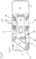
- FIGS. 11 to 18 Further embodiments are in the FIGS. 11 to 18 shown, in which the hinge 100 has at least one energy storage 80.
- the hinge 100 in the embodiments of the FIGS. 11 to 18 has a force memory 80 with variable memory content, wherein the memory contents of the at least one energy accumulator 80 by the pivoting of the at least two fittings 10 and 20 about the pivot 34 is changeable.
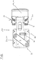
- FIGS. 11 to 14 shows a further hinge with a power storage 80.
- This power storage 80 helps a user close the door by the energy storage 80 when closing the door pushes the drive element 2 down and thus the door can be easily closed.
- FIG. 13 and 14 now shows the hinge 100 in the zero position N after the energy storage 80 has supported the closing of the door.
- the Force memory 80 the provision of at least two fittings 10 and 20 in the zero position N.
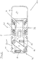
- FIG. 15 and 16 shows a further hinge with a force storage 80.
- This energy storage 80 helps a user to open the door by the energy storage 80 when opening the door pushes the drive element 2 upwards and thus the door can be easily opened.
- the hinge 100 moves out of its zero position N, so the power storage 80 supports this pivoting of the at least two fittings 10 and 20 from this predetermined zero position N out.
- the force accumulator 80 has a longitudinal extent with a longitudinal axis 81 which runs essentially parallel to the axis of rotation 31 of the rotary joint 34.
- the longitudinal axis 81 of the energy accumulator 80 is spaced from the axis of rotation 31 of the rotary joint 34. This allows the hinge 100 to be made smaller than the prior art. Namely, in the prior art, the energy accumulator 80 is seated on the hinge of the hinge, whereby the hinge builds higher.
- the energy accumulator 80 is not fixed in the actuating arm 7 is formed but firmly connected to the fitting 20 and the actuating arm. 7 relative to the energy storage 80 moves. Then, the distance between the longitudinal axis (81) of the energy accumulator (80) and the axis of rotation (31) of the rotary joint (34) during pivoting of the at least two fittings (10, 20) about the axis of rotation (31) of the rotary joint (34) change.
- This variant of the stationary force accumulator 80 is of course intended for all illustrated embodiments. In this case, a guide groove on the actuating arm 7 for the energy accumulator 80 would preferably be provided.
- FIGS. 11 to 14 only one energy storage 80 is shown in each case.
- two or more force accumulator 80 are provided which support the pivoting of the at least two fittings 10 and 20 from the predetermined zero position N.
- two or more energy accumulator 80 are provided, the at least two or more energy storage 80, the provision of at least two fittings 10 and 20 in the successful pivoting of the at least two fittings 10 and 20 from the predetermined zero position support the zero position N.
- the longitudinal axes 31 of these force accumulators 80 are formed parallel to one another in order to achieve a uniform application of force.
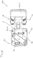
- a further variant of a hinge 100 is shown in which two power storage 80 are provided, of which a force storage 80 at the successful pivoting of the at least two fittings 10 and 20 from the predetermined zero position N, the provision of at least two fittings 10 and 20 in the zero position N. supports and another force storage 80 supports the pivoting of the at least two fittings 10 and 20 from the predetermined zero position. It is also envisaged here that several force accumulators 80 are also provided, of which at least two force accumulators 80 support the return of the at least two fittings 10 and 20 to the zero position N when the at least two fittings 10 and 20 are pivoted out of the predetermined zero position N. and / or at least two other power storage 80 support the pivoting of the at least two fittings 10 and 20 from the predetermined zero position N.
- this hinge 100 operates only with a power storage 80, either to open the door or close.
- the second energy storage 80 is disabled to do so, for example, expanded.
- an opening assist or a closing assist can be achieved, and two different hinges need not be produced.
- the energy accumulator 80 is designed as a spring.
- springs especially preferred coil springs are used, which are designed as compression springs.
- the energy storage 80 supports in all embodiments of FIGS. 11 to 18 the adjustment of the two fittings 10 and 20 in the direction parallel to the axis of rotation 31.
- the embodiments of the FIGS. 11 to 18 supports the power storage 80 and the adjustment of the two fittings 10 and 20 in the direction perpendicular to the axis of rotation 31st
- FIGS. 11 to 18 applies mutatis mutandis that in the embodiment of FIGS. 1 to 6c Mentioned.
- FIGS. 1 to 6c Mentioned.
- FIGS. 7a it is also conceivable to equip this with a power storage to facilitate the opening and / or closing the door.
Landscapes
- Engineering & Computer Science (AREA)
- Mechanical Engineering (AREA)
- Hinges (AREA)
Claims (9)
- Charnière (100) pour le pivotement d'une porte (101), en particulier pour la porte (101) d'une séparation de douche (110), avec- au moins deux ferrures (10, 20) qui sont reliées ensemble par un pivot (4), une des ferrures (10) étant conçue comme une ferrure de porte (11) et une autre ferrure (20) comme une contre-ferrure (21), les deux ferrures (10, 20) étant reliées ensemble de façon pivotante autour d'un axe de rotation (31) par une articulation tournante (34) en formant une fente (32) présentant une largeur de fente (33) et- un dispositif de réglage (70), dans lequel le dispositif de réglage (70) présente au moins un profil de réglage (41, 141) et au moins un élément de réglage (42, 43), dans lequel le au moins un élément de réglage (42, 43) s'appuie, d'une part, sur le au moins un profil de réglage (41, 141) et, d'autre part, sur l'une des deux ferrures (10, 20), caractérisée en ce que le pivot (4) est conçu de manière solidaire en rotation sur la ferrure de porte (11), le profil de réglage (41) étant conçu sur le pivot (4), le pivot (4) étant relié par un élément d'entraînement (2) à la contre-ferrure (21) et le dispositif de réglage (70) accomplissant un déplacement des deux ferrures (10, 20) le long d'un sens parallèle à l'axe de rotation (31), et en ce que le dispositif de réglage (70) présente un guidage (5), le guidage (5) présentant une section conçue comme une rampe (1) avec un plan incliné (3), sur lequel l'élément d'entraînement (2) peut être entraîné essentiellement de façon rectiligne, ce par quoi un déplacement de l'élément d'entraînement (2) le long de la section provoque un mouvement combiné des deux ferrures (10, 20) à angles droits l'une par rapport à l'autre vers, en modifiant la largeur de fente (33), et le long de l'axe de rotation (31).
- Charnière selon la revendication 1, caractérisée en ce que le pivot (4) présente au moins par endroits une section différente de la forme circulaire.
- Charnière selon l'une des revendications 1 à 2, caractérisée en ce que le dispositif de réglage (70) présente un dispositif d'ajustement (50) pour ajuster la course de la porte (101) de sorte que la porte (101) peut être réglée par rapport au mur (102) non seulement en angle mais aussi à distance, le dispositif d'ajustement (50) présentant au moins un élément d'ajustement (52, 53) qui correspond à l'élément de réglage (42, 43), l'élément d'ajustement (52, 53) étant adjacent à l'élément de réglage (42, 43).
- Charnière selon l'une des revendications 1 à 3, caractérisée en ce qu'au moins un accumulateur d'énergie (80) est prévu entre la ferrure (10, 20) et le dispositif de réglage (70) avec un contenu de l'accumulateur modifiable et en ce que le contenu de l'accumulateur du au moins un accumulateur d'énergie (80) est modifiable par un pivotement des au moins deux ferrures (10, 20) autour de l'articulation tournante (34).
- Charnière selon la revendication 4, caractérisée en ce que le au moins un accumulateur d'énergie (80) est inséré de manière telle entre la ferrure (10, 20) et le dispositif de réglage (70), qu'il soutient le déplacement des deux ferrures (10, 20) dans le sens parallèlement à l'axe de rotation (31).
- Charnière selon la revendication 4 ou 5, caractérisée en ce qu'après le pivotement des au moins deux ferrures (10, 20) depuis une position zéro prédéterminée (N), le au moins un accumulateur d'énergie (80) est inséré de manière telle entre la ferrure (10, 20) et le dispositif de réglage (70), qu'il soutient un mouvement en retour des au moins deux ferrures (10, 20) dans la position zéro (N).
- Charnière selon la revendication 5 ou 6, caractérisée en ce que le au moins un accumulateur d'énergie (80) est inséré de manière telle entre la ferrure (10, 20) et le dispositif de réglage (70), qu'il soutient un pivotement des au moins deux ferrures (10, 20) depuis la position zéro (N) prédéterminée.
- Charnière selon la revendication 6 ou 7, caractérisée en ce qu'au moins deux accumulateurs d'énergie (80) sont insérés de manière telle entre la ferrure (10, 20) et le dispositif de réglage (70), qu'au moins un des accumulateurs d'énergie (80), après le pivotement des au moins deux ferrures (10, 20) depuis la position zéro prédéterminée (N), soutient le mouvement en retour des au moins deux ferrures (10, 20) dans la position zéro (N) et un autre des au moins deux accumulateurs d'énergie (80) soutient le pivotement des au moins deux ferrures (10, 20) depuis la position zéro prédéterminée (N).
- Séparation de douche (110) avec au moins une charnière (100)-de préférence au moins deux charnières (100) - pour le pivotement d'une porte (101) par rapport à un mur (102) selon l'une des revendications 1 à 8.
Applications Claiming Priority (1)
| Application Number | Priority Date | Filing Date | Title |
|---|---|---|---|
| AT8062012 | 2012-07-19 |
Publications (3)
| Publication Number | Publication Date |
|---|---|
| EP2687660A2 EP2687660A2 (fr) | 2014-01-22 |
| EP2687660A3 EP2687660A3 (fr) | 2015-09-16 |
| EP2687660B1 true EP2687660B1 (fr) | 2016-12-21 |
Family
ID=48906076
Family Applications (1)
| Application Number | Title | Priority Date | Filing Date |
|---|---|---|---|
| EP13003620.5A Active EP2687660B1 (fr) | 2012-07-19 | 2013-07-18 | Charnière |
Country Status (1)
| Country | Link |
|---|---|
| EP (1) | EP2687660B1 (fr) |
Families Citing this family (7)
| Publication number | Priority date | Publication date | Assignee | Title |
|---|---|---|---|---|
| CN105401810A (zh) * | 2015-12-21 | 2016-03-16 | 中山市福瑞卫浴设备有限公司 | 一种新型铰链 |
| CN106978948A (zh) * | 2016-01-18 | 2017-07-25 | 罗东 | 一种高端私密合页系统 |
| CN107419980B (zh) * | 2017-08-30 | 2022-10-28 | 福建西河卫浴科技有限公司 | 一种无缝升降铰链结构 |
| IT201700123436A1 (it) | 2017-10-30 | 2019-04-30 | Steelco Spa | Macchina di trattamento di oggetti, in particolare di lavaggio, termodisinfezione e/o sterilizzazione di oggetti |
| AT521842B1 (de) * | 2018-11-13 | 2023-01-15 | Blum Gmbh Julius | Möbelscharnier |
| DE102020207128B3 (de) | 2020-06-08 | 2021-11-25 | Kermi Gmbh | Scharnier mit integrierter Anschlagdämpfung |
| CN121097582B (zh) * | 2025-11-10 | 2026-02-10 | 浙江绿丰电气有限公司 | 一种电缆分支箱 |
Family Cites Families (2)
| Publication number | Priority date | Publication date | Assignee | Title |
|---|---|---|---|---|
| DE20304008U1 (de) * | 2003-03-12 | 2003-07-10 | Schulte Duschkabinenbau GmbH & Co. KG, 59846 Sundern | Halterung, Schwenklager und Duschabtrennung |
| AT10648U1 (de) | 2008-04-02 | 2009-07-15 | Duka Ag | Türband für ein an einem wandelement schwenkbar gelagertes türelement, insbesondere duschtrennwand |
-
2013
- 2013-07-18 EP EP13003620.5A patent/EP2687660B1/fr active Active
Non-Patent Citations (1)
| Title |
|---|
| None * |
Also Published As
| Publication number | Publication date |
|---|---|
| EP2687660A2 (fr) | 2014-01-22 |
| EP2687660A3 (fr) | 2015-09-16 |
Similar Documents
| Publication | Publication Date | Title |
|---|---|---|
| EP2687660B1 (fr) | Charnière | |
| EP3475508B1 (fr) | Ferrure de meuble | |
| EP2702219B1 (fr) | Meuble doté d'un corps et un clapet pliant | |
| EP2539528B1 (fr) | Porte relevante munie d'un guidage mobile de vantail | |
| EP3452681B1 (fr) | Dispositif d'étanchéité pour une porte couilissante | |
| EP0065109B1 (fr) | Charnière | |
| EP2828460B1 (fr) | Ferrure de fenetre ou porte avec un battant deplaceable vers un plan parallèle et coulissable horizontalement dans ledit plan parallèle | |
| EP2737152A1 (fr) | Portail relevable comportant un guidage mobile des éléments du portail | |
| DE202017100971U1 (de) | Montagevorrichtung zum Einsetzen von Rahmenelementen in Wandöffnungen | |
| EP3348761B1 (fr) | Dispositif de fixation pivotante d'un vantail de porte sur un dormant | |
| EP3622141B1 (fr) | Charnière anti-pincement et procédé de réglage des éléments de retenue d'une telle charnière | |
| EP0451737A2 (fr) | Ferrure d'articulation pour meuble d'angle | |
| DE202011004678U1 (de) | Schrank mit einem Scharnier | |
| DE102011085177A1 (de) | Antriebssystem für ein KFZ-Dachsystem | |
| DE3334298C3 (de) | Verschluß für Fenster, Türen oder dergleichen | |
| AT15365U1 (de) | Verglasungssystem | |
| AT13763U1 (de) | Scharnier | |
| EP0074502A1 (fr) | Porte à élements | |
| EP3998906B1 (fr) | Composant de meuble | |
| EP1176276A1 (fr) | Structure de verrouillage autoverrouillable avec possibilité de réglage | |
| EP1400646A2 (fr) | Charnière fixée en feuillure pour porte ou fenêtre | |
| EP2826939A2 (fr) | Charnière | |
| DE19825071C2 (de) | Parallelausstellfenster mit Drehfunktion | |
| DE29517703U1 (de) | Mechanische Feststellvorrichtung für Türflügel mit einem Türschließer | |
| AT15329U1 (de) | Einstellbarer Beschlag - insbesondere Scharnier für einen Türflügel |
Legal Events
| Date | Code | Title | Description |
|---|---|---|---|
| PUAI | Public reference made under article 153(3) epc to a published international application that has entered the european phase |
Free format text: ORIGINAL CODE: 0009012 |
|
| AK | Designated contracting states |
Kind code of ref document: A2 Designated state(s): AL AT BE BG CH CY CZ DE DK EE ES FI FR GB GR HR HU IE IS IT LI LT LU LV MC MK MT NL NO PL PT RO RS SE SI SK SM TR |
|
| AX | Request for extension of the european patent |
Extension state: BA ME |
|
| PUAL | Search report despatched |
Free format text: ORIGINAL CODE: 0009013 |
|
| AK | Designated contracting states |
Kind code of ref document: A3 Designated state(s): AL AT BE BG CH CY CZ DE DK EE ES FI FR GB GR HR HU IE IS IT LI LT LU LV MC MK MT NL NO PL PT RO RS SE SI SK SM TR |
|
| AX | Request for extension of the european patent |
Extension state: BA ME |
|
| RIC1 | Information provided on ipc code assigned before grant |
Ipc: E05D 3/02 20060101ALI20150807BHEP Ipc: E05D 7/00 20060101AFI20150807BHEP Ipc: E05D 7/04 20060101ALI20150807BHEP |
|
| 17P | Request for examination filed |
Effective date: 20151218 |
|
| RBV | Designated contracting states (corrected) |
Designated state(s): AL AT BE BG CH CY CZ DE DK EE ES FI FR GB GR HR HU IE IS IT LI LT LU LV MC MK MT NL NO PL PT RO RS SE SI SK SM TR |
|
| 17Q | First examination report despatched |
Effective date: 20160216 |
|
| GRAP | Despatch of communication of intention to grant a patent |
Free format text: ORIGINAL CODE: EPIDOSNIGR1 |
|
| INTG | Intention to grant announced |
Effective date: 20160810 |
|
| GRAS | Grant fee paid |
Free format text: ORIGINAL CODE: EPIDOSNIGR3 |
|
| STAA | Information on the status of an ep patent application or granted ep patent |
Free format text: STATUS: GRANT OF PATENT IS INTENDED |
|
| GRAJ | Information related to disapproval of communication of intention to grant by the applicant or resumption of examination proceedings by the epo deleted |
Free format text: ORIGINAL CODE: EPIDOSDIGR1 |
|
| GRAL | Information related to payment of fee for publishing/printing deleted |
Free format text: ORIGINAL CODE: EPIDOSDIGR3 |
|
| STAA | Information on the status of an ep patent application or granted ep patent |
Free format text: STATUS: EXAMINATION IS IN PROGRESS |
|
| GRAR | Information related to intention to grant a patent recorded |
Free format text: ORIGINAL CODE: EPIDOSNIGR71 |
|
| STAA | Information on the status of an ep patent application or granted ep patent |
Free format text: STATUS: GRANT OF PATENT IS INTENDED |
|
| GRAA | (expected) grant |
Free format text: ORIGINAL CODE: 0009210 |
|
| STAA | Information on the status of an ep patent application or granted ep patent |
Free format text: STATUS: THE PATENT HAS BEEN GRANTED |
|
| INTC | Intention to grant announced (deleted) | ||
| INTG | Intention to grant announced |
Effective date: 20161109 |
|
| AK | Designated contracting states |
Kind code of ref document: B1 Designated state(s): AL AT BE BG CH CY CZ DE DK EE ES FI FR GB GR HR HU IE IS IT LI LT LU LV MC MK MT NL NO PL PT RO RS SE SI SK SM TR |
|
| REG | Reference to a national code |
Ref country code: GB Ref legal event code: FG4D Free format text: NOT ENGLISH |
|
| REG | Reference to a national code |
Ref country code: CH Ref legal event code: EP |
|
| REG | Reference to a national code |
Ref country code: IE Ref legal event code: FG4D Free format text: LANGUAGE OF EP DOCUMENT: GERMAN |
|
| REG | Reference to a national code |
Ref country code: AT Ref legal event code: REF Ref document number: 855661 Country of ref document: AT Kind code of ref document: T Effective date: 20170115 |
|
| REG | Reference to a national code |
Ref country code: CH Ref legal event code: NV Representative=s name: ISLER AND PEDRAZZINI AG, CH |
|
| REG | Reference to a national code |
Ref country code: DE Ref legal event code: R096 Ref document number: 502013005801 Country of ref document: DE |
|
| PG25 | Lapsed in a contracting state [announced via postgrant information from national office to epo] |
Ref country code: LV Free format text: LAPSE BECAUSE OF FAILURE TO SUBMIT A TRANSLATION OF THE DESCRIPTION OR TO PAY THE FEE WITHIN THE PRESCRIBED TIME-LIMIT Effective date: 20161221 |
|
| REG | Reference to a national code |
Ref country code: NL Ref legal event code: FP |
|
| REG | Reference to a national code |
Ref country code: LT Ref legal event code: MG4D |
|
| PG25 | Lapsed in a contracting state [announced via postgrant information from national office to epo] |
Ref country code: GR Free format text: LAPSE BECAUSE OF FAILURE TO SUBMIT A TRANSLATION OF THE DESCRIPTION OR TO PAY THE FEE WITHIN THE PRESCRIBED TIME-LIMIT Effective date: 20170322 Ref country code: NO Free format text: LAPSE BECAUSE OF FAILURE TO SUBMIT A TRANSLATION OF THE DESCRIPTION OR TO PAY THE FEE WITHIN THE PRESCRIBED TIME-LIMIT Effective date: 20170321 Ref country code: LT Free format text: LAPSE BECAUSE OF FAILURE TO SUBMIT A TRANSLATION OF THE DESCRIPTION OR TO PAY THE FEE WITHIN THE PRESCRIBED TIME-LIMIT Effective date: 20161221 Ref country code: SE Free format text: LAPSE BECAUSE OF FAILURE TO SUBMIT A TRANSLATION OF THE DESCRIPTION OR TO PAY THE FEE WITHIN THE PRESCRIBED TIME-LIMIT Effective date: 20161221 |
|
| PG25 | Lapsed in a contracting state [announced via postgrant information from national office to epo] |
Ref country code: RS Free format text: LAPSE BECAUSE OF FAILURE TO SUBMIT A TRANSLATION OF THE DESCRIPTION OR TO PAY THE FEE WITHIN THE PRESCRIBED TIME-LIMIT Effective date: 20161221 Ref country code: FI Free format text: LAPSE BECAUSE OF FAILURE TO SUBMIT A TRANSLATION OF THE DESCRIPTION OR TO PAY THE FEE WITHIN THE PRESCRIBED TIME-LIMIT Effective date: 20161221 Ref country code: HR Free format text: LAPSE BECAUSE OF FAILURE TO SUBMIT A TRANSLATION OF THE DESCRIPTION OR TO PAY THE FEE WITHIN THE PRESCRIBED TIME-LIMIT Effective date: 20161221 |
|
| PG25 | Lapsed in a contracting state [announced via postgrant information from national office to epo] |
Ref country code: CZ Free format text: LAPSE BECAUSE OF FAILURE TO SUBMIT A TRANSLATION OF THE DESCRIPTION OR TO PAY THE FEE WITHIN THE PRESCRIBED TIME-LIMIT Effective date: 20161221 Ref country code: EE Free format text: LAPSE BECAUSE OF FAILURE TO SUBMIT A TRANSLATION OF THE DESCRIPTION OR TO PAY THE FEE WITHIN THE PRESCRIBED TIME-LIMIT Effective date: 20161221 Ref country code: SK Free format text: LAPSE BECAUSE OF FAILURE TO SUBMIT A TRANSLATION OF THE DESCRIPTION OR TO PAY THE FEE WITHIN THE PRESCRIBED TIME-LIMIT Effective date: 20161221 Ref country code: IS Free format text: LAPSE BECAUSE OF FAILURE TO SUBMIT A TRANSLATION OF THE DESCRIPTION OR TO PAY THE FEE WITHIN THE PRESCRIBED TIME-LIMIT Effective date: 20170421 Ref country code: RO Free format text: LAPSE BECAUSE OF FAILURE TO SUBMIT A TRANSLATION OF THE DESCRIPTION OR TO PAY THE FEE WITHIN THE PRESCRIBED TIME-LIMIT Effective date: 20161221 |
|
| REG | Reference to a national code |
Ref country code: FR Ref legal event code: PLFP Year of fee payment: 5 |
|
| PG25 | Lapsed in a contracting state [announced via postgrant information from national office to epo] |
Ref country code: PT Free format text: LAPSE BECAUSE OF FAILURE TO SUBMIT A TRANSLATION OF THE DESCRIPTION OR TO PAY THE FEE WITHIN THE PRESCRIBED TIME-LIMIT Effective date: 20170421 Ref country code: PL Free format text: LAPSE BECAUSE OF FAILURE TO SUBMIT A TRANSLATION OF THE DESCRIPTION OR TO PAY THE FEE WITHIN THE PRESCRIBED TIME-LIMIT Effective date: 20161221 Ref country code: ES Free format text: LAPSE BECAUSE OF FAILURE TO SUBMIT A TRANSLATION OF THE DESCRIPTION OR TO PAY THE FEE WITHIN THE PRESCRIBED TIME-LIMIT Effective date: 20161221 Ref country code: SM Free format text: LAPSE BECAUSE OF FAILURE TO SUBMIT A TRANSLATION OF THE DESCRIPTION OR TO PAY THE FEE WITHIN THE PRESCRIBED TIME-LIMIT Effective date: 20161221 Ref country code: BG Free format text: LAPSE BECAUSE OF FAILURE TO SUBMIT A TRANSLATION OF THE DESCRIPTION OR TO PAY THE FEE WITHIN THE PRESCRIBED TIME-LIMIT Effective date: 20170321 |
|
| REG | Reference to a national code |
Ref country code: DE Ref legal event code: R097 Ref document number: 502013005801 Country of ref document: DE |
|
| PLBE | No opposition filed within time limit |
Free format text: ORIGINAL CODE: 0009261 |
|
| STAA | Information on the status of an ep patent application or granted ep patent |
Free format text: STATUS: NO OPPOSITION FILED WITHIN TIME LIMIT |
|
| 26N | No opposition filed |
Effective date: 20170922 |
|
| PG25 | Lapsed in a contracting state [announced via postgrant information from national office to epo] |
Ref country code: DK Free format text: LAPSE BECAUSE OF FAILURE TO SUBMIT A TRANSLATION OF THE DESCRIPTION OR TO PAY THE FEE WITHIN THE PRESCRIBED TIME-LIMIT Effective date: 20161221 |
|
| PG25 | Lapsed in a contracting state [announced via postgrant information from national office to epo] |
Ref country code: SI Free format text: LAPSE BECAUSE OF FAILURE TO SUBMIT A TRANSLATION OF THE DESCRIPTION OR TO PAY THE FEE WITHIN THE PRESCRIBED TIME-LIMIT Effective date: 20161221 |
|
| GBPC | Gb: european patent ceased through non-payment of renewal fee |
Effective date: 20170718 |
|
| REG | Reference to a national code |
Ref country code: IE Ref legal event code: MM4A |
|
| PG25 | Lapsed in a contracting state [announced via postgrant information from national office to epo] |
Ref country code: GB Free format text: LAPSE BECAUSE OF NON-PAYMENT OF DUE FEES Effective date: 20170718 Ref country code: IE Free format text: LAPSE BECAUSE OF NON-PAYMENT OF DUE FEES Effective date: 20170718 |
|
| PG25 | Lapsed in a contracting state [announced via postgrant information from national office to epo] |
Ref country code: LU Free format text: LAPSE BECAUSE OF NON-PAYMENT OF DUE FEES Effective date: 20170718 |
|
| REG | Reference to a national code |
Ref country code: FR Ref legal event code: PLFP Year of fee payment: 6 |
|
| PG25 | Lapsed in a contracting state [announced via postgrant information from national office to epo] |
Ref country code: MT Free format text: LAPSE BECAUSE OF FAILURE TO SUBMIT A TRANSLATION OF THE DESCRIPTION OR TO PAY THE FEE WITHIN THE PRESCRIBED TIME-LIMIT Effective date: 20161221 |
|
| PG25 | Lapsed in a contracting state [announced via postgrant information from national office to epo] |
Ref country code: MC Free format text: LAPSE BECAUSE OF FAILURE TO SUBMIT A TRANSLATION OF THE DESCRIPTION OR TO PAY THE FEE WITHIN THE PRESCRIBED TIME-LIMIT Effective date: 20161221 Ref country code: HU Free format text: LAPSE BECAUSE OF FAILURE TO SUBMIT A TRANSLATION OF THE DESCRIPTION OR TO PAY THE FEE WITHIN THE PRESCRIBED TIME-LIMIT; INVALID AB INITIO Effective date: 20130718 |
|
| PG25 | Lapsed in a contracting state [announced via postgrant information from national office to epo] |
Ref country code: CY Free format text: LAPSE BECAUSE OF NON-PAYMENT OF DUE FEES Effective date: 20161221 |
|
| PG25 | Lapsed in a contracting state [announced via postgrant information from national office to epo] |
Ref country code: MK Free format text: LAPSE BECAUSE OF FAILURE TO SUBMIT A TRANSLATION OF THE DESCRIPTION OR TO PAY THE FEE WITHIN THE PRESCRIBED TIME-LIMIT Effective date: 20161221 |
|
| PG25 | Lapsed in a contracting state [announced via postgrant information from national office to epo] |
Ref country code: TR Free format text: LAPSE BECAUSE OF FAILURE TO SUBMIT A TRANSLATION OF THE DESCRIPTION OR TO PAY THE FEE WITHIN THE PRESCRIBED TIME-LIMIT Effective date: 20161221 |
|
| PG25 | Lapsed in a contracting state [announced via postgrant information from national office to epo] |
Ref country code: AL Free format text: LAPSE BECAUSE OF FAILURE TO SUBMIT A TRANSLATION OF THE DESCRIPTION OR TO PAY THE FEE WITHIN THE PRESCRIBED TIME-LIMIT Effective date: 20161221 |
|
| PGFP | Annual fee paid to national office [announced via postgrant information from national office to epo] |
Ref country code: NL Payment date: 20250723 Year of fee payment: 13 |
|
| PGFP | Annual fee paid to national office [announced via postgrant information from national office to epo] |
Ref country code: DE Payment date: 20250722 Year of fee payment: 13 |
|
| PGFP | Annual fee paid to national office [announced via postgrant information from national office to epo] |
Ref country code: IT Payment date: 20250731 Year of fee payment: 13 |
|
| PGFP | Annual fee paid to national office [announced via postgrant information from national office to epo] |
Ref country code: BE Payment date: 20250722 Year of fee payment: 13 |
|
| PGFP | Annual fee paid to national office [announced via postgrant information from national office to epo] |
Ref country code: FR Payment date: 20250723 Year of fee payment: 13 Ref country code: AT Payment date: 20250625 Year of fee payment: 13 |
|
| PGFP | Annual fee paid to national office [announced via postgrant information from national office to epo] |
Ref country code: CH Payment date: 20250801 Year of fee payment: 13 |