EP2687706B1 - Procédé d'inversion à fréquences multiples et appareil de commande pour génératrice entraînée par un moteur à combustion interne - Google Patents
Procédé d'inversion à fréquences multiples et appareil de commande pour génératrice entraînée par un moteur à combustion interne Download PDFInfo
- Publication number
- EP2687706B1 EP2687706B1 EP12757828.4A EP12757828A EP2687706B1 EP 2687706 B1 EP2687706 B1 EP 2687706B1 EP 12757828 A EP12757828 A EP 12757828A EP 2687706 B1 EP2687706 B1 EP 2687706B1
- Authority
- EP
- European Patent Office
- Prior art keywords
- output voltage
- unit
- value
- frequency
- output
- Prior art date
- Legal status (The legal status is an assumption and is not a legal conclusion. Google has not performed a legal analysis and makes no representation as to the accuracy of the status listed.)
- Active
Links
- 238000002485 combustion reaction Methods 0.000 title claims description 39
- 238000000034 method Methods 0.000 title claims description 21
- 238000006243 chemical reaction Methods 0.000 claims description 44
- 238000010586 diagram Methods 0.000 description 11
- 238000005516 engineering process Methods 0.000 description 4
- 238000012986 modification Methods 0.000 description 3
- 230000004048 modification Effects 0.000 description 3
- 230000000295 complement effect Effects 0.000 description 2
- 239000003990 capacitor Substances 0.000 description 1
- 230000005611 electricity Effects 0.000 description 1
- 238000010248 power generation Methods 0.000 description 1
- 238000005070 sampling Methods 0.000 description 1
Images


Classifications
-
- H—ELECTRICITY
- H02—GENERATION; CONVERSION OR DISTRIBUTION OF ELECTRIC POWER
- H02M—APPARATUS FOR CONVERSION BETWEEN AC AND AC, BETWEEN AC AND DC, OR BETWEEN DC AND DC, AND FOR USE WITH MAINS OR SIMILAR POWER SUPPLY SYSTEMS; CONVERSION OF DC OR AC INPUT POWER INTO SURGE OUTPUT POWER; CONTROL OR REGULATION THEREOF
- H02M5/00—Conversion of AC power input into AC power output, e.g. for change of voltage, for change of frequency, for change of number of phases
- H02M5/40—Conversion of AC power input into AC power output, e.g. for change of voltage, for change of frequency, for change of number of phases with intermediate conversion into DC
- H02M5/42—Conversion of AC power input into AC power output, e.g. for change of voltage, for change of frequency, for change of number of phases with intermediate conversion into DC by static converters
- H02M5/44—Conversion of AC power input into AC power output, e.g. for change of voltage, for change of frequency, for change of number of phases with intermediate conversion into DC by static converters using discharge tubes or semiconductor devices to convert the intermediate DC into AC
-
- F—MECHANICAL ENGINEERING; LIGHTING; HEATING; WEAPONS; BLASTING
- F02—COMBUSTION ENGINES; HOT-GAS OR COMBUSTION-PRODUCT ENGINE PLANTS
- F02D—CONTROLLING COMBUSTION ENGINES
- F02D29/00—Controlling engines, such controlling being peculiar to the devices driven thereby, the devices being other than parts or accessories essential to engine operation, e.g. controlling of engines by signals external thereto
- F02D29/06—Controlling engines, such controlling being peculiar to the devices driven thereby, the devices being other than parts or accessories essential to engine operation, e.g. controlling of engines by signals external thereto peculiar to engines driving electric generators
-
- H—ELECTRICITY
- H02—GENERATION; CONVERSION OR DISTRIBUTION OF ELECTRIC POWER
- H02P—CONTROL OR REGULATION OF ELECTRIC MOTORS, ELECTRIC GENERATORS OR DYNAMO-ELECTRIC CONVERTERS; CONTROLLING TRANSFORMERS, REACTORS OR CHOKE COILS
- H02P9/00—Arrangements for controlling electric generators for the purpose of obtaining a desired output
- H02P9/04—Control effected upon non-electric prime mover and dependent upon electric output value of the generator
-
- H—ELECTRICITY
- H02—GENERATION; CONVERSION OR DISTRIBUTION OF ELECTRIC POWER
- H02M—APPARATUS FOR CONVERSION BETWEEN AC AND AC, BETWEEN AC AND DC, OR BETWEEN DC AND DC, AND FOR USE WITH MAINS OR SIMILAR POWER SUPPLY SYSTEMS; CONVERSION OF DC OR AC INPUT POWER INTO SURGE OUTPUT POWER; CONTROL OR REGULATION THEREOF
- H02M7/00—Conversion of AC power input into DC power output; Conversion of DC power input into AC power output
- H02M7/42—Conversion of DC power input into AC power output without possibility of reversal
- H02M7/44—Conversion of DC power input into AC power output without possibility of reversal by static converters
- H02M7/48—Conversion of DC power input into AC power output without possibility of reversal by static converters using discharge tubes with control electrode or semiconductor devices with control electrode
- H02M7/53—Conversion of DC power input into AC power output without possibility of reversal by static converters using discharge tubes with control electrode or semiconductor devices with control electrode using devices of a triode or transistor type requiring continuous application of a control signal
- H02M7/537—Conversion of DC power input into AC power output without possibility of reversal by static converters using discharge tubes with control electrode or semiconductor devices with control electrode using devices of a triode or transistor type requiring continuous application of a control signal using semiconductor devices only, e.g. single switched pulse inverters
- H02M7/5387—Conversion of DC power input into AC power output without possibility of reversal by static converters using discharge tubes with control electrode or semiconductor devices with control electrode using devices of a triode or transistor type requiring continuous application of a control signal using semiconductor devices only, e.g. single switched pulse inverters in a bridge configuration
- H02M7/53871—Conversion of DC power input into AC power output without possibility of reversal by static converters using discharge tubes with control electrode or semiconductor devices with control electrode using devices of a triode or transistor type requiring continuous application of a control signal using semiconductor devices only, e.g. single switched pulse inverters in a bridge configuration with automatic control of output voltage or current
- H02M7/53878—Conversion of DC power input into AC power output without possibility of reversal by static converters using discharge tubes with control electrode or semiconductor devices with control electrode using devices of a triode or transistor type requiring continuous application of a control signal using semiconductor devices only, e.g. single switched pulse inverters in a bridge configuration with automatic control of output voltage or current by time shifting switching signals of one diagonal pair of the bridge with respect to the other diagonal pair
Definitions
- the present invention relates to the technical field of generator control, and in particular to a multiple-frequency inversion method and a control apparatus for an internal combustion engine driven generator.
- FIG. 1 the figure is a structural diagram of an internal combustion engine driven generator in the prior art.
- An internal combustion engine 101 functioning as a prime motor, drives a generator 102 to generate electricity.
- An alternating current outputted by the generator 102 is rectified into a direct current by a rectifying unit 103, and the direct current is outputted to an inverter unit 104 subsequently.
- the inverter unit 104 Controlled by a controller 105, the inverter unit 104 inverts the direct current into a required alternating current which is provided to a load after being filtered by a filter unit 106.
- the controller 105 controls the opening degree of the throttle of the internal combustion engine 101 through a throttle controller 107.
- a common inversion technology applied in the prior art results in relatively large device parameters in the subsequent filter unit, further causing relatively large output internal resistance of the generator and relatively low non-linear load capability.
- US 2002/0074974 A1 discloses a method and apparatus for overload-controlling inverter power generation apparatus.
- US 2005/0242783 A1 discloses an inverter controlled generator set.
- Ned Mohan ETAL Single-Phase Inverters
- a solution to solve the technical problem of the present invention is to provide a multiple-frequency inversion method and a control apparatus for an internal combustion engine driven generator so as to reduce device parameters in a filter unit and internal resistance of a generator and provide non-linear load capability.
- the present invention provides a multiple-frequency inversion method for an internal combustion engine driven generator, comprising:
- the multiple-frequency inversion method further comprising: performing positive amplitude conversion for the output current of the filter unit; subtracting a reference value from the output current having undergone the positive amplitude conversion; performing analog-to-digital conversion for the output current with the reference value subtracted and then calculate an effective value of the output current; according to the effective value of the output current, looking up a preset revolving speed-current curve to obtain a corresponding target revolving speed; controlling the opening degree of the throttle of the internal combustion engine so that the revolving speed of the internal combustion engine reaches the target revolving speed.
- the present invention further provides a multiple-frequency inversion apparatus for an internal combustion engine driven generator, comprising: an output voltage rectifying unit configured to rectify the output voltage of a filter unit, wherein the filter unit is a LC low pass filter; an output voltage analog-to-digital conversion unit configured to perform analog-to-digital conversion for the rectified output voltage; an output voltage calculating unit configured to calculate the average value of the output voltage or an effective value for the output voltage according to the output voltage having undergone the analog-to-digital conversion; a comparing unit configured to compare the average value of the output voltage with a target voltage value or compare the effective value of the output voltage with a target voltage value; a control unit configured to, according to the comparison results, adjusting the proportionality coefficient of two sine with a 180-degree phase difference in a table of sine until the average value or the effective value of the output voltage falls within a preset range of the target voltage value; the table of sine is used for generating two sine waves with a 180-degree phase difference, and the two sine waves with a 180
- the multiple-frequency inversion apparatus further comprising: a positive amplitude conversion unit configured to perform positive amplitude conversion for the output current of the filter unit; a subtracting unit configured to subtract a reference value from the output current having undergone the positive amplitude conversion; an output current analog-to-digital conversion configured to perform analog-to-digital conversion for the output current with the reference value subtracted; an output current effective value calculating unit configured to calculate the effective value of the output current according to the output current having undergone the analog-to-digital conversion; a target revolving speed looking up unit configured to, according to the effective value of the output current, look up a preset revolving speed-current curve to obtain a corresponding target revolving speed; a throttle opening degree control unit configured to control the opening degree of the throttle of the internal combustion engine so that the revolving speed of the internal combustion engine reaches the target revolving speed.
- a positive amplitude conversion unit configured to perform positive amplitude conversion for the output current of the filter unit
- an inverter unit employs a multiple-frequency inversion technology, controlling the inverter unit through a low switching frequency f to obtain a 2f modulated frequency, thus resolving the problem that a low frequency switching component generates a high frequency modulated waveform.
- Four switching tubes in the inverter unit have the same working frequency, alleviating the controller load.
- a high modulated frequency reduces the device parameters of the filter unit, resulting in a smaller-sized and lighter apparatus, thus giving the generator portability.
- Reduction of the device parameters of the filter unit means reduction of the output internal resistance of the generator, therefore increasing the non-linear load capability of the generator and ensuring a good sinusoidal voltage of the generator with a load with a large harmonic current.
- FIG. 2 the figure is a flowchart of the first embodiment of a multiple-frequency inversion method of an internal combustion engine driven generator of the present invention.
- the controller may calculate the average value of the output voltage independently.
- the effective value of the output voltage may be also calculated by a controller with strong calculating ability.
- Step 203 compare the average value of the output voltage with a target voltage value or compare the effective value of the output voltage with a target voltage value;
- Step 204 according to the comparison results, adjust the proportionality coefficient of two sine with a 180-degree phase difference in a table of sine until the average value or the effective value of the output voltage falls within a preset range of the target voltage value; the table of sine is used for generating two sine waves with a 180-degree phase difference, and the two sine waves with a 180-degree phase difference are compared with a triangle wave to generate four PWM waves which have pulse frequency f, and the triangle wave has a frequency f; the four PWM waves which have pulse frequency f drive switching tubes in an inverter unit to enable the inverter unit to output modulated wave with a pulse frequency 2f.
- the inverter unit employs a multiple-frequency inversion technology, controlling the inverter unit through a low switching frequency f to obtain a 2f modulated frequency, thus resolving the problem that a low frequency switching component generates a high frequency modulated waveform.
- Four switching tubes in the inverter unit have the same working frequency, alleviating the controller load.
- a high modulated frequency reduces the device parameters of the filter unit, resulting in a smaller-sized and lighter apparatus, thus giving the generator portability.
- Reduction of the device parameters of the filter unit means reduction of the output internal resistance of the generator, therefore increasing the non-linear load capability of the generator and ensuring a good sinusoidal voltage of the generator with a load with a large harmonic current.
- the method provided by the present invention judges by using the average value of the output voltage, thus alleviating the computational load, so that the control unit is provided with more resources to process other events.
- the average value can be detected precisely only when the waveform distortion of the output voltage is in a certain range. Since the present invention applies a multiple-frequency inversion manner, the waveform distortion of the generator is relatively small under a linear load. Therefore, an average value sampling method can satisfy the precision requirement of voltage regulation.
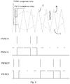
- FIG. 3 the figure is a multiple-frequency inversion waveform diagram provided by the present invention, Wherein, sine wave A and sine wave B are two sine waves with a 180-degree phase difference.
- triangle wave C is modulated with sine wave A to generate PWM1H and modulated with sine wave B to generate PWM2H in each period of triangle wave C,
- a complementary waveform of PWM1H is PWM1L
- a complementary waveform of PWM2H is PWM2L.
- the pulse period of the four PWM waves, PWM1 H, PWM1 L, PWM2H and PWM2L are also f.
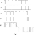
- Four switching tubes in an inverter unit are driven by the four PWM waves so as to make the switching tubes turn on or off. It should be noted that the inverter unit in the present embodiment is a full bridge inverter unit.
- the four switching tubes in the inverter unit are respectively represented by S1, S2, S3 and S4, then waveforms of driving signals of the four switching tubes are as shown in Fig. 4 .
- Output waveforms of the inverter unit are represented by U in Fig. 4 and U represents sine wave of the output voltage. The frequency of U has been multiplied into 2f.
- triangle wave C is generated by a PWM generating module in the controller.
- Sine wave A and sine wave B are obtained by internal programs of the controller, specifically a discrete table of sine changing according to sine.
- the output voltage of a filter unit may be adjusted by adjusting the proportionality coefficient of the sine in the sine waves.
- the prevent invention performs controlling through voltage PI control and current PI control at the same time.
- Voltage PI control mainly controls the output voltage and current PI control mainly controls the revolving speed of the internal combustion engine.
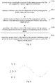
- FIG. 5 the figure is a flowchart of a current PI control method during multiple-frequency inversion of the present invention.
- the present invention further provides a multiple-frequency inversion apparatus for an internal combustion engine driven generator. Components of the apparatus will be described in details below in combination with specific embodiments.
- FIG. 7 the figure is a structural diagram of the first embodiment of a multiple-frequency inversion apparatus for an internal combustion engine driven generator of the present invention.
- the multiple-frequency inversion apparatus for the internal combustion engine driven generator of the present invention includes:
- the inverter unit employs a multiple-frequency inversion technology, controlling the inverter unit through a low switching frequency f to obtain a 2f modulated frequency, thus resolving the problem that a low frequency switching component generates a high frequency modulated waveform.
- Four switching tubes in the inverter unit have the same working frequency, alleviating the controller load.
- a high modulated frequency reduces the device parameters of the filter unit, resulting in a smaller-sized and lighter apparatus, thus giving the generator portability.
- Reduction of the device parameters of the filter unit means reduction of the output internal resistance of the generator, therefore increasing the non-linear load capability of the generator and ensuring a good sinusoidal voltage of the generator with a load with a large harmonic current.
- the prevent invention performs controlling through voltage PI control and current PI control at the same time.
- Voltage PI control mainly controls the output voltage and current PI control mainly controls the revolving speed of the internal combustion engine.
- FIG. 8 the figure is a structural diagram of the second embodiment of an apparatus provided by the present invention.
- a positive amplitude conversion unit 801 is configured to perform positive amplitude conversion for the output current of a filter unit; a subtracting unit 802 is configured to subtract a reference value from the output current having undergone the positive amplitude conversion; an output current analog-to-digital conversion 803 is configured to perform analog-to-digital conversion for the output current with the reference value subtracted; an output current effective value calculating unit 804 is configured to calculate the effective value of the output current according to the output current having undergone the analog-to-digital conversion; a target revolving speed looking up unit 805 is configured to, according to the effective value of the output current, look up a preset revolving speed current curve to obtain a corresponding target revolving speed; a throttle opening degree control unit 806 is configured to control the opening degree of the throttle of the internal combustion engine so that the revolving speed of the internal combustion engine reaches the target revolving speed.
- the filter unit is a LC low-pass filter. Since the frequency of the output voltage of the inverter unit is 2f, the values of inductors and capacitors in the LC low-pass filter can be reduced to reduce the volume of the filter unit. In addition, reduction of the L and C values means reduction of the output internal resistance of the generator, therefore increasing the non-linear load capability of the generator.
Landscapes
- Engineering & Computer Science (AREA)
- Power Engineering (AREA)
- Chemical & Material Sciences (AREA)
- Combustion & Propulsion (AREA)
- Mechanical Engineering (AREA)
- General Engineering & Computer Science (AREA)
- Control Of Eletrric Generators (AREA)
- Ac-Ac Conversion (AREA)
Claims (4)
- Procédé d'inversion à fréquences multiples pour un générateur entraîné par un moteur à combustion interne, consistant à :- redresser (201) la tension de sortie d'un filtre, le filtre étant un filtre passe-bas LC,- après une conversion analogique/numérique de la tension de sortie redressée, calculer (202) la valeur moyenne de la tension de sortie ou la valeur efficace de la tension de sortie,- comparer (203) la valeur moyenne de la tension de sortie avec la valeur cible de la tension ou comparer la valeur efficace de la tension de sortie à la valeur cible de la tension,- en fonction du résultat de la comparaison, régler (204) le coefficient de proportionnalité de deux sinus avec une différence de phase de 180° dans une table de sinus jusqu'à ce que la valeur moyenne ou la valeur efficace de la tension de sortie soit descendue dans une plage préréglée de valeurs cibles de tension, la table de sinus étant utilisée pour générer deux ondes sinusoïdales avec un déphasage de 180°, ces deux ondes déphasées à 180° étant comparées à une onde triangulaire pour générer quatre ondes à modulation de largeur d'impulsion PWM ayant une fréquence d'impulsion f et l'onde triangulaire ayant une fréquence f, les quatre ondes PWM ayant une fréquence f d'entraînement des tubes de commutation d'un inverseur pour permettre à l'inverseur de fournir en sortie une onde ondulée ayant une fréquence d'impulsion de 2f.
- Procédé d'inversion à fréquences multiples pour un générateur entraîné par un moteur à combustion interne selon la revendication 1, caractérisé en ce qu'en coutre il consiste à :- effectuer (501) une conversion d'amplitude positive de l'intensité de courant de sortie du filtre par un transformateur d'acquisition d'intensité de courant,- retrancher (502) une valeur de référence de l'intensité de sortie ayant subie la conversion d'amplitude positive,- effectuer (503) une conversion analogique-numérique sur l'intensité de sortie dont on a retranché la valeur de référence puis calculer la valeur efficace de l'intensité de courant de sortie,- en fonction de la valeur efficace de l'intensité de courant de sortie, regarder (504) la courbe vitesse de rotation préréglée-courant pour obtenir une vitesse cible de rotation correspondante,- commander (505) le degré d'ouverture de l'étranglement du moteur à combustion interne de façon que la vitesse de rotation du moteur à combustion atteigne la vitesse cible de rotation.
- Appareil d'inversion à fréquences multiples pour un générateur entraîné par un moteur à combustion interne comprenant :- un redresseur de tension de sortie (701) configuré pour redresser la tension de sortie d'un filtre, le filtre étant un filtre passe-bas LC,- un convertisseur analogique-numérique de tension de sortie (702) configuré pour appliquer une conversion analogique-numérique à la tension de sortie redressée,- un calculateur de tension de sortie (703) configuré pour calculer la valeur moyenne de la tension de sortie ou la valeur efficace de la tension de sortie ayant subie la conversion analogique-numérique,- un comparateur (704) configuré pour comparer la valeur moyenne de la tension de sortie à la valeur cible de tension ou comparer la valeur efficace de la tension de sortie à la valeur cible de la tension,- une unité de commande (705) configurée pour qu'en fonction des résultats de la comparaison, régler le coefficient de proportionnalité de deux courbes sinusoïdales déphasées à 180° dans une table de sinus jusqu'à ce que la valeur moyenne ou la valeur efficace de la tension de sortie arrive dans une plage préréglée de valeurs cible de tension, la table de sinus servant à générer deux ondes sinusoïdales déphasées à 180° et ces deux ondes sinusoïdales déphasées à 180° sont comparées à une onde triangulaire pour générer quatre ondes à modulation de largeur d'impulsion PWM ayant une fréquence d'impulsion f et l'onde triangulaire a une fréquence f, les quatre ondes PWM ayant une fréquence f entraînant des tubes de commutation dans un inverseur pour permettre à l'inverseur de fournir en sortie une onde modulée ayant une fréquence d'impulsion 2f.
- Appareil d'inversion à fréquences multiples pour un générateur entraîné par un moteur à combustion interne selon la revendication 3, caractérisé en ce qu'il comprend en outre :- un convertisseur d'amplitude positive (801) configuré pour faire une conversion d'amplitude positive sur l'intensité de courant de sortie du filtre,- un soustracteur (802) configuré pour retrancher une valeur de référence de l'intensité de sortie ayant subi la conversion d'amplitude positive,- un convertisseur analogique-numérique (803) de l'intensité de courant de sortie pour appliquer une conversion analogique-numérique à l'intensité de courant de sortie, dont on a retranché la valeur de référence,- un calculateur de valeur efficace d'intensité de courant de sortie (804) configuré pour calculer la valeur de l'intensité de sortie en fonction de l'intensité de courant de sortie ayant subi la conversion analogique-numérique,- une table de vitesses cible de rotation (806) configurée pour qu'en fonction de la valeur efficace de l'intensité de courant de sortie, chercher la courbe vitesse de rotation préréglée-courant pour obtenir la vitesse cible de rotation correspondante, et- une commande de degré d'étranglement, configurée pour commander le degré d'ouverture du clapet d'étranglement du moteur à combustion interne de façon que la vitesse de rotation du moteur à combustion interne atteigne la vitesse cible de rotation.
Applications Claiming Priority (2)
| Application Number | Priority Date | Filing Date | Title |
|---|---|---|---|
| CN201110060848XA CN102312737B (zh) | 2011-03-15 | 2011-03-15 | 一种内燃机驱动发电机的倍频逆变方法和装置 |
| PCT/CN2012/071832 WO2012122895A2 (fr) | 2011-03-15 | 2012-03-01 | Procédé d'inversion à fréquences multiples et appareil de commande pour génératrice entraînée par un moteur à combustion interne |
Publications (3)
| Publication Number | Publication Date |
|---|---|
| EP2687706A2 EP2687706A2 (fr) | 2014-01-22 |
| EP2687706A4 EP2687706A4 (fr) | 2015-01-21 |
| EP2687706B1 true EP2687706B1 (fr) | 2021-05-19 |
Family
ID=45426239
Family Applications (1)
| Application Number | Title | Priority Date | Filing Date |
|---|---|---|---|
| EP12757828.4A Active EP2687706B1 (fr) | 2011-03-15 | 2012-03-01 | Procédé d'inversion à fréquences multiples et appareil de commande pour génératrice entraînée par un moteur à combustion interne |
Country Status (6)
| Country | Link |
|---|---|
| US (1) | US8712666B2 (fr) |
| EP (1) | EP2687706B1 (fr) |
| JP (1) | JP5837102B2 (fr) |
| CN (1) | CN102312737B (fr) |
| RU (1) | RU2587170C2 (fr) |
| WO (1) | WO2012122895A2 (fr) |
Families Citing this family (8)
| Publication number | Priority date | Publication date | Assignee | Title |
|---|---|---|---|---|
| CN102312737B (zh) * | 2011-03-15 | 2013-06-19 | 隆鑫通用动力股份有限公司 | 一种内燃机驱动发电机的倍频逆变方法和装置 |
| CN102307036B (zh) * | 2011-03-15 | 2013-06-19 | 隆鑫通用动力股份有限公司 | 一种内燃机驱动发电机组并联运行的控制方法和装置 |
| US9114216B2 (en) | 2012-07-16 | 2015-08-25 | Accunit, Llc | Handheld medical substance dispensing system, apparatus and methods |
| CN103701334B (zh) * | 2013-12-31 | 2017-03-01 | 重庆力华科技有限责任公司 | 一种内燃机驱动的逆变发电装置及其逆变控制方法 |
| US10541634B2 (en) * | 2017-03-17 | 2020-01-21 | Hamilton Sundstrand Corporation | Generator arrangements and methods of controlling generator arrangements |
| CN109698653B (zh) * | 2019-02-28 | 2024-01-09 | 苏州科技大学 | 一种基于透射测速的小型汽油发电机调速控制方法 |
| CN113124953B (zh) * | 2020-01-16 | 2024-10-01 | 广州汽车集团股份有限公司 | 汽车燃油表中油量显示的计量方法、装置及相关设备 |
| US11368106B2 (en) | 2020-03-19 | 2022-06-21 | Hamilton Sundstrand Corporation (HSC) | Power converter PWM |
Family Cites Families (14)
| Publication number | Priority date | Publication date | Assignee | Title |
|---|---|---|---|---|
| GB1271597A (en) * | 1969-08-06 | 1972-04-19 | Nippon Denso Co | Automatic transmission control systems for automatic automtive transmissions |
| JPS5833998A (ja) * | 1981-08-21 | 1983-02-28 | Hitachi Ltd | パルス幅変調インバ−タによる誘導電動機の制御方式 |
| JPS60229674A (ja) * | 1984-04-26 | 1985-11-15 | Kyosan Electric Mfg Co Ltd | 正弦波pwm方式インバ−タ装置 |
| JP3354465B2 (ja) * | 1997-12-22 | 2002-12-09 | 三菱電機株式会社 | 電力変換装置 |
| JP3969623B2 (ja) * | 2000-06-30 | 2007-09-05 | 本田技研工業株式会社 | エンジン駆動発電装置 |
| JP2002186172A (ja) * | 2000-12-14 | 2002-06-28 | Kokusan Denki Co Ltd | インバータ発電装置及びその過負荷時制御方法 |
| JP4561167B2 (ja) * | 2004-04-28 | 2010-10-13 | 国産電機株式会社 | インバータ発電装置 |
| CN2854922Y (zh) * | 2005-11-02 | 2007-01-03 | 珠海泰坦科技股份有限公司 | 单相变频恒流源 |
| CN2888737Y (zh) * | 2005-11-03 | 2007-04-11 | 珠海泰坦科技股份有限公司 | 二倍频单相正弦波脉宽调制输出ip核 |
| JP2010031660A (ja) * | 2008-07-25 | 2010-02-12 | Honda Motor Co Ltd | インバータ発電機 |
| JP2010035260A (ja) * | 2008-07-25 | 2010-02-12 | Honda Motor Co Ltd | インバータ発電機 |
| CN101691116B (zh) * | 2009-11-06 | 2012-08-01 | 唐山轨道客车有限责任公司 | 内燃动车的加速度牵引控制方法 |
| CN102312737B (zh) | 2011-03-15 | 2013-06-19 | 隆鑫通用动力股份有限公司 | 一种内燃机驱动发电机的倍频逆变方法和装置 |
| RU2515474C2 (ru) * | 2011-05-17 | 2014-05-10 | Хонда Мотор Ко., Лтд. | Инверторный генератор |
-
2011
- 2011-03-15 CN CN201110060848XA patent/CN102312737B/zh active Active
-
2012
- 2012-03-01 RU RU2013143884/06A patent/RU2587170C2/ru active
- 2012-03-01 EP EP12757828.4A patent/EP2687706B1/fr active Active
- 2012-03-01 WO PCT/CN2012/071832 patent/WO2012122895A2/fr not_active Ceased
- 2012-03-01 US US14/005,281 patent/US8712666B2/en active Active
- 2012-03-01 JP JP2013558294A patent/JP5837102B2/ja not_active Expired - Fee Related
Non-Patent Citations (1)
| Title |
|---|
| None * |
Also Published As
| Publication number | Publication date |
|---|---|
| US20140001770A1 (en) | 2014-01-02 |
| JP2014508502A (ja) | 2014-04-03 |
| EP2687706A2 (fr) | 2014-01-22 |
| WO2012122895A3 (fr) | 2012-11-08 |
| JP5837102B2 (ja) | 2015-12-24 |
| RU2587170C2 (ru) | 2016-06-20 |
| CN102312737A (zh) | 2012-01-11 |
| CN102312737B (zh) | 2013-06-19 |
| WO2012122895A2 (fr) | 2012-09-20 |
| EP2687706A4 (fr) | 2015-01-21 |
| RU2013143884A (ru) | 2015-04-20 |
| US8712666B2 (en) | 2014-04-29 |
Similar Documents
| Publication | Publication Date | Title |
|---|---|---|
| US8712666B2 (en) | Multiple-frequency inversion method and control apparatus for internal combustion engine driven generator | |
| JP5267589B2 (ja) | 電力変換装置 | |
| US8933588B2 (en) | Method and device for controlling internal combustion engine driven generator set to run in parallel | |
| Li et al. | Active power decoupling for high-power single-phase PWM rectifiers | |
| JP3123079B2 (ja) | Pwm制御変換器の制御装置 | |
| CN104078976B (zh) | 一种光伏系统并网电流的谐波抑制方法、装置及光伏系统 | |
| CA2672827C (fr) | Generatrice avec onduleur | |
| Tokumasu et al. | AC/DC converter based on instantaneous power balance control for reducing DC-link capacitance | |
| CN115632550A (zh) | Apfc变换器控制方法、apfc变换器及工业电源 | |
| WO2011128962A1 (fr) | Dispositif de conversion d'énergie | |
| JP5716631B2 (ja) | 電力変換装置 | |
| Somkun et al. | Fast DC bus voltage control of single-phase PWM rectifiers using a ripple voltage estimator | |
| JP4183523B2 (ja) | インバータ装置及びインバータ装置の制御方法 | |
| Wang et al. | An adaptive hysteresis band controller for LC-coupling hybrid active power filter with approximate constant switching frequency | |
| CN102044874A (zh) | 基于周期离散控制及平均电流补偿逆控制的有源滤波器 | |
| Komurcugil et al. | Investigation of active damping methods for model-based-current-control scheme of single-phase grid-tied VSI with LCL filter | |
| Bahrami-Fard et al. | An Effective Current Harmonic Suppression Strategy for Three-Phase Vienna Rectifiers | |
| Zhang et al. | A Unity Power Factor Control Method of PWM Rectifier | |
| Xu et al. | Improved inverter-side current control for grid-connected ZCZ-filtered inverter with low grid current distortion and high robustness | |
| Bai et al. | Efficiency optimization for active storage unit with adaptive digital control | |
| Li et al. | Model Predictive PWM for Hybrid Active Power Filter | |
| CN105122574B (zh) | 充电系统及其充电操作方法、mpp跟踪方法的充电应用 | |
| Di Donna et al. | Single-phase synchronous active front-end for high power applications | |
| CN119171763A (zh) | 可提高单相离网逆变电压动态响应速度的控制方法和系统 | |
| Lin et al. | DC-Link Capacitor Lifetime Extension for Two-Level Back-to-Back Converters Based on Zero-Sequence Voltage Injection |
Legal Events
| Date | Code | Title | Description |
|---|---|---|---|
| PUAI | Public reference made under article 153(3) epc to a published international application that has entered the european phase |
Free format text: ORIGINAL CODE: 0009012 |
|
| 17P | Request for examination filed |
Effective date: 20130919 |
|
| AK | Designated contracting states |
Kind code of ref document: A2 Designated state(s): AL AT BE BG CH CY CZ DE DK EE ES FI FR GB GR HR HU IE IS IT LI LT LU LV MC MK MT NL NO PL PT RO RS SE SI SK SM TR |
|
| DAX | Request for extension of the european patent (deleted) | ||
| A4 | Supplementary search report drawn up and despatched |
Effective date: 20141219 |
|
| RIC1 | Information provided on ipc code assigned before grant |
Ipc: H02M 7/5387 20070101ALI20141215BHEP Ipc: F02D 29/06 20060101AFI20141215BHEP Ipc: H02P 9/04 20060101ALI20141215BHEP |
|
| STAA | Information on the status of an ep patent application or granted ep patent |
Free format text: STATUS: EXAMINATION IS IN PROGRESS |
|
| 17Q | First examination report despatched |
Effective date: 20170330 |
|
| GRAP | Despatch of communication of intention to grant a patent |
Free format text: ORIGINAL CODE: EPIDOSNIGR1 |
|
| STAA | Information on the status of an ep patent application or granted ep patent |
Free format text: STATUS: GRANT OF PATENT IS INTENDED |
|
| INTG | Intention to grant announced |
Effective date: 20201208 |
|
| GRAS | Grant fee paid |
Free format text: ORIGINAL CODE: EPIDOSNIGR3 |
|
| GRAA | (expected) grant |
Free format text: ORIGINAL CODE: 0009210 |
|
| STAA | Information on the status of an ep patent application or granted ep patent |
Free format text: STATUS: THE PATENT HAS BEEN GRANTED |
|
| AK | Designated contracting states |
Kind code of ref document: B1 Designated state(s): AL AT BE BG CH CY CZ DE DK EE ES FI FR GB GR HR HU IE IS IT LI LT LU LV MC MK MT NL NO PL PT RO RS SE SI SK SM TR |
|
| REG | Reference to a national code |
Ref country code: GB Ref legal event code: FG4D |
|
| REG | Reference to a national code |
Ref country code: CH Ref legal event code: EP |
|
| REG | Reference to a national code |
Ref country code: DE Ref legal event code: R096 Ref document number: 602012075604 Country of ref document: DE |
|
| REG | Reference to a national code |
Ref country code: AT Ref legal event code: REF Ref document number: 1394187 Country of ref document: AT Kind code of ref document: T Effective date: 20210615 |
|
| REG | Reference to a national code |
Ref country code: IE Ref legal event code: FG4D |
|
| REG | Reference to a national code |
Ref country code: LT Ref legal event code: MG9D |
|
| REG | Reference to a national code |
Ref country code: AT Ref legal event code: MK05 Ref document number: 1394187 Country of ref document: AT Kind code of ref document: T Effective date: 20210519 |
|
| REG | Reference to a national code |
Ref country code: NL Ref legal event code: MP Effective date: 20210519 |
|
| PG25 | Lapsed in a contracting state [announced via postgrant information from national office to epo] |
Ref country code: HR Free format text: LAPSE BECAUSE OF FAILURE TO SUBMIT A TRANSLATION OF THE DESCRIPTION OR TO PAY THE FEE WITHIN THE PRESCRIBED TIME-LIMIT Effective date: 20210519 Ref country code: AT Free format text: LAPSE BECAUSE OF FAILURE TO SUBMIT A TRANSLATION OF THE DESCRIPTION OR TO PAY THE FEE WITHIN THE PRESCRIBED TIME-LIMIT Effective date: 20210519 Ref country code: BG Free format text: LAPSE BECAUSE OF FAILURE TO SUBMIT A TRANSLATION OF THE DESCRIPTION OR TO PAY THE FEE WITHIN THE PRESCRIBED TIME-LIMIT Effective date: 20210819 Ref country code: LT Free format text: LAPSE BECAUSE OF FAILURE TO SUBMIT A TRANSLATION OF THE DESCRIPTION OR TO PAY THE FEE WITHIN THE PRESCRIBED TIME-LIMIT Effective date: 20210519 Ref country code: FI Free format text: LAPSE BECAUSE OF FAILURE TO SUBMIT A TRANSLATION OF THE DESCRIPTION OR TO PAY THE FEE WITHIN THE PRESCRIBED TIME-LIMIT Effective date: 20210519 |
|
| PG25 | Lapsed in a contracting state [announced via postgrant information from national office to epo] |
Ref country code: ES Free format text: LAPSE BECAUSE OF FAILURE TO SUBMIT A TRANSLATION OF THE DESCRIPTION OR TO PAY THE FEE WITHIN THE PRESCRIBED TIME-LIMIT Effective date: 20210519 Ref country code: NO Free format text: LAPSE BECAUSE OF FAILURE TO SUBMIT A TRANSLATION OF THE DESCRIPTION OR TO PAY THE FEE WITHIN THE PRESCRIBED TIME-LIMIT Effective date: 20210819 Ref country code: PT Free format text: LAPSE BECAUSE OF FAILURE TO SUBMIT A TRANSLATION OF THE DESCRIPTION OR TO PAY THE FEE WITHIN THE PRESCRIBED TIME-LIMIT Effective date: 20210920 Ref country code: PL Free format text: LAPSE BECAUSE OF FAILURE TO SUBMIT A TRANSLATION OF THE DESCRIPTION OR TO PAY THE FEE WITHIN THE PRESCRIBED TIME-LIMIT Effective date: 20210519 Ref country code: GR Free format text: LAPSE BECAUSE OF FAILURE TO SUBMIT A TRANSLATION OF THE DESCRIPTION OR TO PAY THE FEE WITHIN THE PRESCRIBED TIME-LIMIT Effective date: 20210820 Ref country code: LV Free format text: LAPSE BECAUSE OF FAILURE TO SUBMIT A TRANSLATION OF THE DESCRIPTION OR TO PAY THE FEE WITHIN THE PRESCRIBED TIME-LIMIT Effective date: 20210519 Ref country code: IS Free format text: LAPSE BECAUSE OF FAILURE TO SUBMIT A TRANSLATION OF THE DESCRIPTION OR TO PAY THE FEE WITHIN THE PRESCRIBED TIME-LIMIT Effective date: 20210919 Ref country code: SE Free format text: LAPSE BECAUSE OF FAILURE TO SUBMIT A TRANSLATION OF THE DESCRIPTION OR TO PAY THE FEE WITHIN THE PRESCRIBED TIME-LIMIT Effective date: 20210519 Ref country code: RS Free format text: LAPSE BECAUSE OF FAILURE TO SUBMIT A TRANSLATION OF THE DESCRIPTION OR TO PAY THE FEE WITHIN THE PRESCRIBED TIME-LIMIT Effective date: 20210519 |
|
| PG25 | Lapsed in a contracting state [announced via postgrant information from national office to epo] |
Ref country code: NL Free format text: LAPSE BECAUSE OF FAILURE TO SUBMIT A TRANSLATION OF THE DESCRIPTION OR TO PAY THE FEE WITHIN THE PRESCRIBED TIME-LIMIT Effective date: 20210519 |
|
| PG25 | Lapsed in a contracting state [announced via postgrant information from national office to epo] |
Ref country code: RO Free format text: LAPSE BECAUSE OF FAILURE TO SUBMIT A TRANSLATION OF THE DESCRIPTION OR TO PAY THE FEE WITHIN THE PRESCRIBED TIME-LIMIT Effective date: 20210519 Ref country code: SK Free format text: LAPSE BECAUSE OF FAILURE TO SUBMIT A TRANSLATION OF THE DESCRIPTION OR TO PAY THE FEE WITHIN THE PRESCRIBED TIME-LIMIT Effective date: 20210519 Ref country code: SM Free format text: LAPSE BECAUSE OF FAILURE TO SUBMIT A TRANSLATION OF THE DESCRIPTION OR TO PAY THE FEE WITHIN THE PRESCRIBED TIME-LIMIT Effective date: 20210519 Ref country code: CZ Free format text: LAPSE BECAUSE OF FAILURE TO SUBMIT A TRANSLATION OF THE DESCRIPTION OR TO PAY THE FEE WITHIN THE PRESCRIBED TIME-LIMIT Effective date: 20210519 Ref country code: EE Free format text: LAPSE BECAUSE OF FAILURE TO SUBMIT A TRANSLATION OF THE DESCRIPTION OR TO PAY THE FEE WITHIN THE PRESCRIBED TIME-LIMIT Effective date: 20210519 Ref country code: DK Free format text: LAPSE BECAUSE OF FAILURE TO SUBMIT A TRANSLATION OF THE DESCRIPTION OR TO PAY THE FEE WITHIN THE PRESCRIBED TIME-LIMIT Effective date: 20210519 |
|
| REG | Reference to a national code |
Ref country code: DE Ref legal event code: R097 Ref document number: 602012075604 Country of ref document: DE |
|
| PLBE | No opposition filed within time limit |
Free format text: ORIGINAL CODE: 0009261 |
|
| STAA | Information on the status of an ep patent application or granted ep patent |
Free format text: STATUS: NO OPPOSITION FILED WITHIN TIME LIMIT |
|
| 26N | No opposition filed |
Effective date: 20220222 |
|
| PG25 | Lapsed in a contracting state [announced via postgrant information from national office to epo] |
Ref country code: IS Free format text: LAPSE BECAUSE OF FAILURE TO SUBMIT A TRANSLATION OF THE DESCRIPTION OR TO PAY THE FEE WITHIN THE PRESCRIBED TIME-LIMIT Effective date: 20210919 Ref country code: AL Free format text: LAPSE BECAUSE OF FAILURE TO SUBMIT A TRANSLATION OF THE DESCRIPTION OR TO PAY THE FEE WITHIN THE PRESCRIBED TIME-LIMIT Effective date: 20210519 |
|
| PG25 | Lapsed in a contracting state [announced via postgrant information from national office to epo] |
Ref country code: IT Free format text: LAPSE BECAUSE OF FAILURE TO SUBMIT A TRANSLATION OF THE DESCRIPTION OR TO PAY THE FEE WITHIN THE PRESCRIBED TIME-LIMIT Effective date: 20210519 |
|
| REG | Reference to a national code |
Ref country code: DE Ref legal event code: R119 Ref document number: 602012075604 Country of ref document: DE |
|
| PG25 | Lapsed in a contracting state [announced via postgrant information from national office to epo] |
Ref country code: MC Free format text: LAPSE BECAUSE OF FAILURE TO SUBMIT A TRANSLATION OF THE DESCRIPTION OR TO PAY THE FEE WITHIN THE PRESCRIBED TIME-LIMIT Effective date: 20210519 |
|
| REG | Reference to a national code |
Ref country code: CH Ref legal event code: PL |
|
| GBPC | Gb: european patent ceased through non-payment of renewal fee |
Effective date: 20220301 |
|
| REG | Reference to a national code |
Ref country code: BE Ref legal event code: MM Effective date: 20220331 |
|
| PG25 | Lapsed in a contracting state [announced via postgrant information from national office to epo] |
Ref country code: LU Free format text: LAPSE BECAUSE OF NON-PAYMENT OF DUE FEES Effective date: 20220301 Ref country code: LI Free format text: LAPSE BECAUSE OF NON-PAYMENT OF DUE FEES Effective date: 20220331 Ref country code: IE Free format text: LAPSE BECAUSE OF NON-PAYMENT OF DUE FEES Effective date: 20220301 Ref country code: GB Free format text: LAPSE BECAUSE OF NON-PAYMENT OF DUE FEES Effective date: 20220301 Ref country code: FR Free format text: LAPSE BECAUSE OF NON-PAYMENT OF DUE FEES Effective date: 20220331 Ref country code: DE Free format text: LAPSE BECAUSE OF NON-PAYMENT OF DUE FEES Effective date: 20221001 Ref country code: CH Free format text: LAPSE BECAUSE OF NON-PAYMENT OF DUE FEES Effective date: 20220331 |
|
| PG25 | Lapsed in a contracting state [announced via postgrant information from national office to epo] |
Ref country code: BE Free format text: LAPSE BECAUSE OF NON-PAYMENT OF DUE FEES Effective date: 20220331 |
|
| PG25 | Lapsed in a contracting state [announced via postgrant information from national office to epo] |
Ref country code: HU Free format text: LAPSE BECAUSE OF FAILURE TO SUBMIT A TRANSLATION OF THE DESCRIPTION OR TO PAY THE FEE WITHIN THE PRESCRIBED TIME-LIMIT; INVALID AB INITIO Effective date: 20120301 |
|
| PG25 | Lapsed in a contracting state [announced via postgrant information from national office to epo] |
Ref country code: MK Free format text: LAPSE BECAUSE OF FAILURE TO SUBMIT A TRANSLATION OF THE DESCRIPTION OR TO PAY THE FEE WITHIN THE PRESCRIBED TIME-LIMIT Effective date: 20210519 Ref country code: CY Free format text: LAPSE BECAUSE OF FAILURE TO SUBMIT A TRANSLATION OF THE DESCRIPTION OR TO PAY THE FEE WITHIN THE PRESCRIBED TIME-LIMIT Effective date: 20210519 |
|
| PG25 | Lapsed in a contracting state [announced via postgrant information from national office to epo] |
Ref country code: TR Free format text: LAPSE BECAUSE OF FAILURE TO SUBMIT A TRANSLATION OF THE DESCRIPTION OR TO PAY THE FEE WITHIN THE PRESCRIBED TIME-LIMIT Effective date: 20210519 |
|
| PG25 | Lapsed in a contracting state [announced via postgrant information from national office to epo] |
Ref country code: MT Free format text: LAPSE BECAUSE OF FAILURE TO SUBMIT A TRANSLATION OF THE DESCRIPTION OR TO PAY THE FEE WITHIN THE PRESCRIBED TIME-LIMIT Effective date: 20210519 |