EP2687730A1 - Schneckenstruktur für einen zentrifugalverdichter - Google Patents
Schneckenstruktur für einen zentrifugalverdichter Download PDFInfo
- Publication number
- EP2687730A1 EP2687730A1 EP12757491.1A EP12757491A EP2687730A1 EP 2687730 A1 EP2687730 A1 EP 2687730A1 EP 12757491 A EP12757491 A EP 12757491A EP 2687730 A1 EP2687730 A1 EP 2687730A1
- Authority
- EP
- European Patent Office
- Prior art keywords
- scroll
- flow path
- diffuser
- flow
- chamber
- Prior art date
- Legal status (The legal status is an assumption and is not a legal conclusion. Google has not performed a legal analysis and makes no representation as to the accuracy of the status listed.)
- Granted
Links
Images



Classifications
-
- F—MECHANICAL ENGINEERING; LIGHTING; HEATING; WEAPONS; BLASTING
- F04—POSITIVE - DISPLACEMENT MACHINES FOR LIQUIDS; PUMPS FOR LIQUIDS OR ELASTIC FLUIDS
- F04D—NON-POSITIVE-DISPLACEMENT PUMPS
- F04D29/00—Details, component parts, or accessories
- F04D29/40—Casings; Connections of working fluid
- F04D29/42—Casings; Connections of working fluid for radial or helico-centrifugal pumps
- F04D29/44—Fluid-guiding means, e.g. diffusers
-
- F—MECHANICAL ENGINEERING; LIGHTING; HEATING; WEAPONS; BLASTING
- F04—POSITIVE - DISPLACEMENT MACHINES FOR LIQUIDS; PUMPS FOR LIQUIDS OR ELASTIC FLUIDS
- F04D—NON-POSITIVE-DISPLACEMENT PUMPS
- F04D29/00—Details, component parts, or accessories
- F04D29/40—Casings; Connections of working fluid
- F04D29/42—Casings; Connections of working fluid for radial or helico-centrifugal pumps
- F04D29/4206—Casings; Connections of working fluid for radial or helico-centrifugal pumps especially adapted for elastic fluid pumps
-
- F—MECHANICAL ENGINEERING; LIGHTING; HEATING; WEAPONS; BLASTING
- F04—POSITIVE - DISPLACEMENT MACHINES FOR LIQUIDS; PUMPS FOR LIQUIDS OR ELASTIC FLUIDS
- F04D—NON-POSITIVE-DISPLACEMENT PUMPS
- F04D29/00—Details, component parts, or accessories
- F04D29/40—Casings; Connections of working fluid
- F04D29/42—Casings; Connections of working fluid for radial or helico-centrifugal pumps
- F04D29/44—Fluid-guiding means, e.g. diffusers
- F04D29/441—Fluid-guiding means, e.g. diffusers especially adapted for elastic fluid pumps
-
- F—MECHANICAL ENGINEERING; LIGHTING; HEATING; WEAPONS; BLASTING
- F04—POSITIVE - DISPLACEMENT MACHINES FOR LIQUIDS; PUMPS FOR LIQUIDS OR ELASTIC FLUIDS
- F04D—NON-POSITIVE-DISPLACEMENT PUMPS
- F04D29/00—Details, component parts, or accessories
- F04D29/66—Combating cavitation, whirls, noise, vibration or the like; Balancing
- F04D29/661—Combating cavitation, whirls, noise, vibration or the like; Balancing especially adapted for elastic fluid pumps
- F04D29/667—Combating cavitation, whirls, noise, vibration or the like; Balancing especially adapted for elastic fluid pumps by influencing the flow pattern, e.g. suppression of turbulence
-
- F—MECHANICAL ENGINEERING; LIGHTING; HEATING; WEAPONS; BLASTING
- F05—INDEXING SCHEMES RELATING TO ENGINES OR PUMPS IN VARIOUS SUBCLASSES OF CLASSES F01-F04
- F05D—INDEXING SCHEME FOR ASPECTS RELATING TO NON-POSITIVE-DISPLACEMENT MACHINES OR ENGINES, GAS-TURBINES OR JET-PROPULSION PLANTS
- F05D2250/00—Geometry
- F05D2250/50—Inlet or outlet
- F05D2250/52—Outlet
Definitions
- the present invention relates to a scroll structure (scroll chamber structure) of a centrifugal compressor used in a vehicular turbocharger, a marine turbocharger, and the like.
- a centrifugal compressor which is used in a compressor portion or the like of a vehicular turbocharger or a marine turbocharger imparts kinetic energy to a fluid via rotations of an impeller and increases pressure due to centrifugal force by discharging the fluid outward in a radial direction.
- centrifugal compressors are required to have a high pressure ratio and high efficiency over a wide operating range. Accordingly, various concepts have been devised and implemented for scroll structures.
- Patent Document 1 Japanese Patent No. 4492045
- Japanese Patent No. 4492045 describes a technique with respect to a centrifugal compressor comprising a casing provided with a spirally formed scroll flow path, wherein the scroll flow path is formed such that a flow path width in an axial direction gradually increases from inward to outward in a radial direction and the flow path width is maximum on an outer side in the radial direction of an intermediate point of the flow path width in the radial direction.
- Patent Document 2 Japanese Translation of PCT Application No. 2010-529358 ) describes a centrifugal compressor for a turbocharger, wherein the centrifugal compressor comprises a spiral housing and a diffuser, and the diffuser is formed with an enlarged diameter so as to reduce a negative pressure range in a transitional region or a region in which a tongue portion is positioned in the spiral housing.
- a diffuser 02 is formed on an outer circumferential side of an impeller 01 of a compressor and a scroll flow path 03 is provided on an outer circumferential side of the diffuser 02.
- a cross-sectional shape of the scroll flow path 03 is generally formed in a circular shape, and a flow path connection 04 at a winding start and a winding end of the scroll flow path 03 is connected at a tongue portion 05.
- discharge subsequent to the winding end is to be performed through an outlet flow path 06.
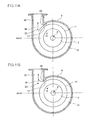
- FIG. 13 shows, on top of each other, scroll cross-sectional shapes taken at angles ⁇ 1 , ⁇ 2 , ... which occur at intervals of a predetermined angle ⁇ in a clockwise direction from the tongue portion 05.
- the flow path connection 04 is shaped such that a circular portion 09 is connected to an outlet portion 011 of the diffuser 02 that is tangent to the circular portion 09.
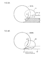
- FIG. 9B is a sectional view taken along line C-C in FIG. 12 , in which the outlet flow path 06 with a circular cross-sectional shape and the scroll flow path 03 with a circular cross-sectional shape intersect with each other to create a ridge line P at an intersection in the vicinity of the tongue portion 05. Therefore, the diffuser outlet flow A has an upward velocity component in the vicinity of the tongue portion 05 and interferes with the scroll flow path internal spiral flow B. Due to the interference, a separation of flow is created in the vicinity of the tongue portion 05 and causes flow loss.
- an object of the present invention is to review a cross-sectional shape of a scroll including a connection to a diffuser outlet in the vicinity of a tongue portion of a scroll flow path as well as over an entire circumference of the scroll and to provide a scroll structure of a centrifugal compressor which improves an effect of loss reduction over a wide operating range including high flow rate operations and low flow rate operations.
- the present invention provides a scroll structure of a centrifugal compressor comprising a diffuser which is provided on an outer circumferential side of an impeller and a scroll flow path which is formed in a spiral shape that connects to an outer circumference of the diffuser, wherein an axial cross-sectional shape of the scroll flow path is a roughly circular shape, a diffuser outlet connected to the roughly circular shape is shifted to a position which is closer to a circle center than to a position of a tangent line to the circular shape and which does not reach the circle center, the roughly circular shape is formed from a scroll chamber which juts out in the axial direction relative to the position of the diffuser outlet and a shift chamber that forms a remainder of the roughly circular shape in a direction opposite to the scroll chamber, and the shift chamber is at least formed on the scroll flow path of a winding end portion in a circumferential direction of a spiral.
- the diffuser outlet flow A has a velocity component that is oriented downward (downward as depicted in FIG. 9A ) in a direction of an axis of rotation of a compressor along a wall surface of the scroll flow path.
- conforming the direction of the diffuser outlet flow A to the flow of the scroll flow path internal spiral flow B and minimizing the occurrence of a ridge line in the vicinity of the tongue portion to reduce ridge line distance combine to minimize interference between the diffuser outlet flow A and the scroll flow path internal spiral flow B, thereby minimizing an occurrence of separation in the vicinity of the tongue portion attributable to the interference and reducing flow loss.
- the shift chamber starts shifting from a position approximately 180 degrees preceding the winding end portion in a circumferential direction and increases so as to reach maximum at a position of approximately 360 degrees, and a shift amount increases linearly or parabolically as a circumferential angle increases.
- a shape of the shift chamber in a circumferential direction changes in a smooth manner to minimize loss in a flow in a circumferential direction in the scroll flow path.
- the shift chamber is further formed in the scroll flow path of a winding start portion.
- a shape of a connection opening of the scroll flow path of the winding start portion to the winding end portion is formed in a flat shape having a height that is equal to a width of the diffuser outlet, the shift chamber is provided on one side of the flat shape, and a height of the shift chamber varies in the circumferential direction.
- forming a shift chamber in a winding start portion is effective in reducing flow loss that occurs in a flow from the vicinity of the tongue portion toward the side of the outlet flow path during a high flow rate operation.
- a circulation area can be reduced in comparison to a connection having a circular cross-sectional shape.
- the shift chamber is formed on the entire scroll flow path in the circumferential direction.
- the shift chamber is formed over an entire circumference in this manner, operational effects attributable to the formation of the shift chamber in the winding start portion and the winding end portion are produced. At the same time, compared to forming the shift chamber in one portion in the circumferential direction, manufacturing is simplified and flow loss in the circumferential direction in the scroll flow path can be minimized.
- the diffuser outlet flow A has a velocity component that is oriented downward in an axial direction along a wall surface of the scroll flow path.
- FIG. 1 shows a schematic diagram of an axial cross-section of a centrifugal compressor 1 according to the present invention.
- the present embodiment represents a centrifugal compressor 1 applied to a turbocharger, wherein a plurality of compressor blades 7 is erected on a surface of a hub 5 fixed to a rotary shaft 3 driven by a turbine (not shown) and a compressor housing 9 covers the outside of the compressor blades 7.
- a diffuser 11 is formed on an outer circumferential side of the compressor blades 7, and a scroll flow path 13 is formed around and connected to the diffuser 11.
- FIG. 2 shows an overall sectional view of the scroll flow path 13.
- the compressor housing 9 comprises the scroll flow path 13 and a linear outlet flow path 15 which communicates with the scroll flow path 13.
- a flow path sectional area of the scroll flow path 13 increases as a winding angle ⁇ increases from a winding start portion 17 of the scroll flow path 13 in a clockwise direction as shown in FIG. 2 .
- a cross-sectional shape of the scroll flow path 13 in an axial direction of the rotary shaft 3 has a roughly circular shape.
- the cross-sectional shape of the scroll flow path 13 includes shifting the outlet portion 11a of the diffuser 11 to a position which is closer to a circle center than to a position of a tangent line to the circular shape and which does not reach the circle center.
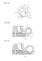
- the roughly circular shape is formed from a scroll chamber 30 which juts out in the axial direction (upward in FIG. 3 ) relative to the position of the outlet portion 11a of the diffuser 11 and a shift chamber 32 that forms a remainder of the roughly circular shape in a direction opposite to the scroll chamber 30 (downward in FIG. 3 ).
- the shift chamber 32 forms a bottom surface portion of the circular shape.
- the cross-sectional shape of the scroll flow path as a whole which combines the scroll chamber 30 and the shift chamber 32 is a roughly circular shape, it is to be understood that the roughly circular shape also includes an oval shape, an ellipse shape, and the like which approximate a circle.
- the cross-sectional shape of the scroll flow path 13 at the winding end portion 19 is shifted downward by a shift amount ⁇ from a bottom surface 11b of the outlet portion 11a of the diffuser 11.
- a lower surface of the shift chamber 32 may be formed by an inclined surface that is set at an inclination angle ⁇ with respect to an end portion of the bottom surface 11b of the diffuser 11 instead of by an arc surface.
- the arc surface or the inclined surface provided on the lower surface of the shift chamber 32 may be provided on a bearing housing 50 as shown in FIG. 3C instead of on the compressor housing 9 as shown in FIG. 3B .
- the diffuser outlet flow may not flow along the inclined surface and may cause separation.
- a favorable range of the inclination angle ⁇ is approximately 3 to 25 degrees.
- a more favorable range is 3 to 15 degrees, and an optimal range is 3 to 8 degrees.
- the inclination angle ⁇ is also included in the range described above in an optimal range of the shift amount ⁇ .
- the inclined surface need not necessarily be linear. In this case, an angle formed by connecting a lower surface of the diffuser outlet and a lower surface of the shift chamber may be considered to be the inclination angle ⁇ .
- the diffuser outlet flow is converted to a velocity component that is oriented downward in an axial direction along a wall surface as shown in FIG. 10A . Therefore, since directions of the diffuser outlet flow A and the scroll flow path internal spiral flow B conform to each other as shown in FIG. 10A , a collision between the scroll flow path internal spiral flow B and the diffuser outlet flow A is avoided and loss is minimized and, at the same time, an occurrence of separation in the vicinity of the tongue portion is minimized.
- the diffuser outlet can conceivably be shifted to a position which is closer to a circle center with respect to the circular cross-sectional shape of the scroll flow path 13 by adopting a shape in which the diffuser outlet is positioned at the circle center.
- the diffuser outlet flow A is uniformly divided into upward and downward directions in the scroll flow path 13.
- a spiral direction of the scroll flow path internal spiral flow B does not stabilize and interference between the flows causes flow loss.
- the outlet portion 11a of the diffuser 11 is shifted to a position which is closer to a circle center than to a position of a tangent line to the circular shape and which does not reach the circle center.
- the shift chamber 32 is formed in the scroll flow path 13 in the winding end portion 19 in the circumferential direction of the spiral, interference between the diffuser outlet flow A and the scroll flow path internal spiral flow B in the vicinity of the tongue portion 25 that is a connection between the winding end portion 19 and the winding start portion 17 is prevented. As a result, an occurrence of separation in the vicinity of the tongue portion attributable to the interference is minimized and an occurrence of flow loss is minimized.
- the diffuser outlet flow A has a velocity component that is oriented downward in an axial direction along a wall surface of the scroll flow path as shown in FIG. 9A .
- a circular cross-sectional shape and a circular cross-sectional shape intersect with each other out of alignment to cause an intersection to bulge in a mountain shape and create a ridge line P.
- a connection position of the outlet portion 11a of the diffuser to a position which is closer to a circle center than to a position of a tangent line to the circular shape and which does not reach the circle center as shown in FIG. 9A , even if a circular shape and a circular shape intersect with each other out of alignment, a ridge line is less likely to be created at the intersection. Therefore, the occurrence of the ridge line P in the vicinity of the tongue portion can be minimized and a distance of a ridge line portion can be reduced.
- conforming the direction of the diffuser outlet flow A to the flow of the scroll flow path internal spiral flow B and minimizing the occurrence of the ridge line P in the vicinity of the tongue portion 25 to reduce ridge line distance combine to minimize interference between the diffuser outlet flow A and the scroll flow path internal spiral flow B, thereby minimizing an occurrence of separation in the vicinity of the tongue portion attributable to the interference and reducing flow loss.
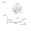
- the shift chamber 32 is to start shifting from a position approximately 180 degrees preceding the winding end portion 19 in a circumferential direction and increase so as to reach maximum at a position of approximately 360 degrees, and a shift amount ⁇ increases linearly or parabolically as a circumferential angle increases.
- the predetermined shift amount ⁇ is subsequently retained in the winding end portion 19.
- the shape of the shift chamber 32 in the circumferential direction changes in a smooth manner to minimize loss in a flow in the circumferential direction in the scroll flow path 13.
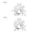
- the second embodiment is characterized in that, in addition to the shift chamber 32 according to the first embodiment, a shift chamber 34 is further formed in the scroll flow path 13 in the winding start portion 17.
- the shift chamber 34 that is similar to the shift chamber 32 described in the first embodiment is formed in the winding start portion 17 in which the winding angle ⁇ is in a range of ⁇ 1 , ⁇ 2 , and ⁇ 3 .
- a lower surface of the shift chamber 34 may be formed by an inclined surface that is set at an inclination angle ⁇ with respect to an end portion of the bottom surface 11b of the diffuser 11 instead of by an arc surface.
- the shift amount ⁇ increases or decreases linearly or parabolically as a circumferential angle increases.
- the shift chamber 32 is formed at the winding end portion 19.
- the shift chamber 32 is only formed at the winding end portion 19, it is difficult to prevent interference during a high flow rate operation between the scroll flow path internal spiral flow B and the diffuser outlet flow A in the scroll flow path 13 (the winding end portion 19) that is oriented from the winding start portion 17 toward (in the direction of the arrow Y) the outlet flow path 15 (the winding end portion 19).
- the third embodiment is characterized in that a shift chamber 36 is formed in the scroll flow path 13 over an entire circumferential direction in addition to the first and second embodiments.
- the shift chamber 36 is formed, in the circumferential direction, over an entire range of the winding angle ⁇ from ⁇ 1 to ⁇ n .
- the shift amount ⁇ of the shift chamber 36 is kept constant as depicted by a dashed-dotted line L 3 in FIG. 8 , the shift amount ⁇ of the shift chamber 36 need not necessarily be constant over the entire circumference.
- An optimum setting may be adopted by respectively setting different shift amounts ⁇ for the winding end portion 19 and the winding start portion 17 and other portions.
- a lower surface of the shift chamber 36 may be formed by an inclined surface that is set at an inclination angle ⁇ with respect to an end portion of the bottom surface at the outlet 11a of the diffuser 11 instead of by an arc surface. This is similar to the first and second embodiments.
- the shift chamber 36 is formed over the entire circumference, operational effects attributable to the shift chambers in the winding start portion 17 and the winding end portion 19 according to the first and second embodiments described above are produced. At the same time, compared to forming a shift chamber in one portion in the circumferential direction, manufacturing is simplified and flow loss in the circumferential direction in the scroll flow path 13 can be minimized.
- the tendency described above is particularly notable in cross sections at positions with winding angles ⁇ of 180° to 270° which are distant from the scroll outlet.
- the low surface of the scroll is positioned below the low surface of the diffuser by the shift amount ⁇ over the entire circumference of the scroll cross section, even if a misalignment of the core occurs during casting, as long as the amount of misalignment is equal to or less than the shift amount ⁇ of the scroll cross section, manufacturing can be carried out in a stable manner without any inconveniences with respect to the misalignment of the core during casting.
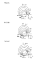
- the fourth embodiment is characterized in that a shape of an opening 39 where the winding start portion 17 connects to the winding end portion 19 of the scroll flow path 13 is formed in a flat shape having a height that is equal to a width of the outlet portion 11a of the diffuser 11, a shift chamber is provided on one side of the flat shape, and a height of the shift chamber varies along the circumferential direction.
- the first example shown in FIG. 6A represents a structure of the opening 39 in which the cross-sectional shape of the scroll flow path 13 is formed in a flat shape having a height that is equal to a width W of the outlet portion 11a of the diffuser 11 and a shift chamber 38a is provided on one side (a bottom surface 11b) of the flat shape.
- the shift chamber 38a is provided in the scroll flow path 13 at the winding end portion 19 in a similar manner to the first embodiment. As exemplified by shapes at positions ⁇ n and ⁇ n-1 in FIG. 3 , the cross-sectional shape is shifted downward by a shift amount ⁇ from the bottom surface 11b of the outlet portion 11a of the diffuser 11.
- a lower surface of the shift chamber 38a may be formed by an inclined surface that is set at an inclination angle ⁇ with respect to an end portion of the bottom surface 11b of the diffuser 11 instead of by an arc surface.
- the shift amount ⁇ and the shift position are similar to those in the description of the first embodiment.
- An effect produced by providing the shift chamber 38a in the scroll flow path 13 at the winding end portion 19 is the same as in the first embodiment. Since a direction of the diffuser outlet flow A can be conformed to the flow of the scroll flow path internal spiral flow B, interference between the diffuser outlet flow A and the scroll flow path internal spiral flow B can be prevented and an occurrence of separation in the vicinity of the tongue portion 25 attributable to the interference can be minimized.
- the shape of the opening 39 is formed in a flat shape with a height that is equal to a width of the outlet portion 11a of the diffuser 11, since a circulation area can be reduced in comparison to a connection having a circular cross-sectional shape, inflow of the recirculating flow (the arrow Z in FIG. 11A ) from the output flow path (the winding end portion 19 of the scroll flow path 13) toward the vicinity of the tongue portion 25 that is created during a low flow rate operation can be minimized.
- the opening 39 of the winding start portion 17 is formed in a flat shape having a height that is equal to a width of the outlet portion 11a of the diffuser 11, inflow of the scroll flow path internal spiral flow B in the outlet flow path 15 (the winding end portion 19 of the scroll flow path) as an inflow E into the scroll flow path 13 at the winding start portion 17 is prevented.
- flow loss due to separation in an arc-shaped cross section of the winding start portion such as that shown in FIG. 10A can be reduced.
- the second example shown in FIG. 6B represents a structure of the opening 39 in which the cross-sectional shape of the scroll flow path 13 is formed in a flat shape having a height that is equal to the width W of the outlet portion 11a of the diffuser 11 and, in addition to the shift chamber 38a provided at the winding end portion 17, a shift chamber 38b is also provided at the winding start portion 17.
- the third example shown in FIG. 6C represents a structure of the opening 39 in which the cross-sectional shape of the scroll flow path 13 is formed in a flat shape having a height that is equal to the width W of the outlet portion 11a of the diffuser 11 and a shift chamber 38c is provided over the entire circumferential direction.
- the fifth embodiment is a modification of the fourth embodiment and is similar to the fourth embodiment in that a shape of the opening 39 where the winding start portion 17 connects to the winding end portion 19 of the scroll flow path 13 is formed in a flat shape having a height that is equal to a width of the outlet portion 11a of the diffuser 11, a shift chamber 40 is provided on one side of the flat shape, and a height of the shift chamber 40 varies along the circumferential direction.
- the fifth embodiment is characterized in that the flat shape changes to a circular shape at ⁇ 2 and ⁇ 3 such that one of the flat surfaces of the opening 39 having a height that is equal to a height of the diffuser 11 is conformed to one side of the diffuser 11 in the height direction, a surface of the opening 39 which opposes the outlet portion 11a of the diffuser 11 is formed in an arc shape, and the arc shape changes so as to gradually expand and return to a circular shape.
- a flow discharged from the diffuser 11 proceeds as a spiral flow that is increasingly biased toward the outer circumference of the scroll. Therefore, by sequentially expanding the arc shape to attain a circular shape by conforming to the flow, a shape change in accordance with the flow discharged from the diffuser 11 can be realized. As a result, unnecessary changes in cross-sectional shapes can be avoided and a return to a circular shape can be realized in a smoother and more efficient manner.
- a smooth flow inside the scroll flow path 13 can be realized due to an efficient cross-sectional shape, and since there is no excess shape with respect to the spiral flow, a compact and downsized cross-sectional shape can be formed which contributes to downsizing and weight reduction of an entire compressor.
- the present invention is suitably used in a scroll of a centrifugal compressor since a cross-sectional shape of a scroll including a connection to a diffuser outlet in the vicinity of a tongue portion of a scroll flow path as well as over an entire circumference of the scroll is reviewed and an improvement in an effect of loss reduction over a wide operating range including high flow rate operations and low flow rate operations can be expected.
Landscapes
- Engineering & Computer Science (AREA)
- Mechanical Engineering (AREA)
- General Engineering & Computer Science (AREA)
- Structures Of Non-Positive Displacement Pumps (AREA)
Applications Claiming Priority (2)
| Application Number | Priority Date | Filing Date | Title |
|---|---|---|---|
| JP2011059935A JP5517981B2 (ja) | 2011-03-17 | 2011-03-17 | 遠心圧縮機のスクロール構造 |
| PCT/JP2012/051891 WO2012124388A1 (ja) | 2011-03-17 | 2012-01-27 | 遠心圧縮機のスクロール構造 |
Publications (3)
| Publication Number | Publication Date |
|---|---|
| EP2687730A1 true EP2687730A1 (de) | 2014-01-22 |
| EP2687730A4 EP2687730A4 (de) | 2014-12-17 |
| EP2687730B1 EP2687730B1 (de) | 2018-11-07 |
Family
ID=46830469
Family Applications (1)
| Application Number | Title | Priority Date | Filing Date |
|---|---|---|---|
| EP12757491.1A Active EP2687730B1 (de) | 2011-03-17 | 2012-01-27 | Zentrifugalverdichter mit schneckenstruktur |
Country Status (5)
| Country | Link |
|---|---|
| US (1) | US9562541B2 (de) |
| EP (1) | EP2687730B1 (de) |
| JP (1) | JP5517981B2 (de) |
| CN (1) | CN103415707B (de) |
| WO (1) | WO2012124388A1 (de) |
Families Citing this family (13)
| Publication number | Priority date | Publication date | Assignee | Title |
|---|---|---|---|---|
| JP5517914B2 (ja) * | 2010-12-27 | 2014-06-11 | 三菱重工業株式会社 | 遠心圧縮機のスクロール構造 |
| CN103242173A (zh) * | 2013-05-21 | 2013-08-14 | 苏州科捷生物医药有限公司 | 2-氟-3-碘苯胺的制备方法 |
| KR102126865B1 (ko) * | 2013-09-04 | 2020-06-25 | 한화파워시스템 주식회사 | 스크롤 텅 및 이를 구비한 회전 기계 |
| JP6638159B2 (ja) * | 2016-03-30 | 2020-01-29 | 三菱重工エンジン&ターボチャージャ株式会社 | 圧縮機スクロール、および、遠心圧縮機 |
| JP6294391B2 (ja) * | 2016-06-28 | 2018-03-14 | 本田技研工業株式会社 | コンプレッサ及び内燃機関の過給システム |
| JP6642711B2 (ja) | 2016-07-01 | 2020-02-12 | 株式会社Ihi | 遠心圧縮機 |
| CN110234888B (zh) * | 2017-03-28 | 2022-09-27 | 三菱重工发动机和增压器株式会社 | 压缩机的涡旋形状以及增压器 |
| US11073164B2 (en) | 2017-11-06 | 2021-07-27 | Mitsubishi Heavy Industries Engine & Turbocharger, Ltd. | Centrifugal compressor and turbocharger including the same |
| JP7013316B2 (ja) * | 2018-04-26 | 2022-01-31 | 三菱重工コンプレッサ株式会社 | 遠心圧縮機 |
| US11905969B2 (en) | 2019-06-05 | 2024-02-20 | Mitsubishi Heavy Industries Engine & Turbocharger, Ltd. | Scroll structure of centrifugal compressor and centrifugal compressor |
| CN111120405B (zh) * | 2019-12-12 | 2021-05-25 | 中国科学院工程热物理研究所 | 一种轴向偏置的非对称蜗壳及其设计方法 |
| US12031546B2 (en) * | 2020-04-17 | 2024-07-09 | Mitsubishi Heavy Industries Engine & Turbocharger, Ltd. | Scroll casing and centrifugal compressor |
| CN115698516B (zh) * | 2020-05-21 | 2025-06-27 | 三菱重工发动机和增压器株式会社 | 蜗壳和离心压缩机 |
Family Cites Families (15)
| Publication number | Priority date | Publication date | Assignee | Title |
|---|---|---|---|---|
| US494890A (en) * | 1893-04-04 | eateatj | ||
| JPS5892423U (ja) * | 1981-12-18 | 1983-06-22 | 本田技研工業株式会社 | コンプレツサハウジング装置 |
| JPH03217699A (ja) | 1990-01-23 | 1991-09-25 | Nissan Motor Co Ltd | 圧縮機のスクロール構造 |
| JPH0542699U (ja) | 1991-11-07 | 1993-06-11 | 日産自動車株式会社 | 車両用送風装置 |
| DE4331606C1 (de) | 1993-09-17 | 1994-10-06 | Gutehoffnungshuette Man | Spiralgehäuse für Turbomaschinen |
| JP3975501B2 (ja) * | 1997-03-17 | 2007-09-12 | 株式会社Ihi | 遠心圧縮機 |
| JPH11303796A (ja) * | 1998-04-24 | 1999-11-02 | Kubota Corp | 遠心ポンプや遠心送風機などの流体機械のケーシング |
| JP2000064994A (ja) * | 1998-08-21 | 2000-03-03 | Ishikawajima Harima Heavy Ind Co Ltd | 遠心圧縮機 |
| DE10245798B4 (de) | 2002-10-01 | 2004-08-19 | Robert Bosch Gmbh | Elektrisch betriebener Ladeluftverdichter mit integrierter Luftkühlung |
| JP4492045B2 (ja) | 2003-06-13 | 2010-06-30 | 株式会社Ihi | 遠心圧縮機 |
| JP2007211717A (ja) | 2006-02-10 | 2007-08-23 | Toyota Motor Corp | 遠心圧縮機 |
| JP2009024582A (ja) * | 2007-07-19 | 2009-02-05 | Ihi Corp | ガス圧縮装置及びガス圧縮装置の制御方法 |
| DE102007034236A1 (de) | 2007-07-23 | 2009-02-05 | Continental Automotive Gmbh | Radialverdichter mit einem Diffusor für den Einsatz bei einem Turbolader |
| JP5305139B2 (ja) * | 2008-09-24 | 2013-10-02 | 株式会社Ihi | 酸素圧縮機用部品における難燃性被膜の形成方法及び酸素圧縮機 |
| US8602728B2 (en) * | 2010-02-05 | 2013-12-10 | Cameron International Corporation | Centrifugal compressor diffuser vanelet |
-
2011
- 2011-03-17 JP JP2011059935A patent/JP5517981B2/ja not_active Expired - Fee Related
-
2012
- 2012-01-27 US US13/981,042 patent/US9562541B2/en not_active Expired - Fee Related
- 2012-01-27 EP EP12757491.1A patent/EP2687730B1/de active Active
- 2012-01-27 WO PCT/JP2012/051891 patent/WO2012124388A1/ja not_active Ceased
- 2012-01-27 CN CN201280012280.7A patent/CN103415707B/zh active Active
Also Published As
| Publication number | Publication date |
|---|---|
| JP5517981B2 (ja) | 2014-06-11 |
| US9562541B2 (en) | 2017-02-07 |
| EP2687730B1 (de) | 2018-11-07 |
| US20130343885A1 (en) | 2013-12-26 |
| EP2687730A4 (de) | 2014-12-17 |
| JP2012193716A (ja) | 2012-10-11 |
| CN103415707A (zh) | 2013-11-27 |
| WO2012124388A1 (ja) | 2012-09-20 |
| CN103415707B (zh) | 2016-08-10 |
Similar Documents
| Publication | Publication Date | Title |
|---|---|---|
| EP2687730B1 (de) | Zentrifugalverdichter mit schneckenstruktur | |
| JP2012193716A5 (de) | ||
| EP2610502B1 (de) | Radialverdichter umfassend einen spiraldurchlass | |
| EP2249002B1 (de) | Radialschneckenstruktur für eine turbine | |
| US8956118B2 (en) | Impeller of centrifugal compressor | |
| US7934904B2 (en) | Diffuser and exhaust system for turbine | |
| EP2055893B1 (de) | Mischflussturbine oder radialturbine | |
| US9765781B2 (en) | Scroll compressor | |
| CN103261622A (zh) | 涡轮的涡旋部构造 | |
| US20160319683A1 (en) | Turbine | |
| WO2013128539A1 (ja) | 回転機械 | |
| JP5029024B2 (ja) | 遠心圧縮機 | |
| WO2023187913A1 (ja) | 斜流タービン及びターボチャージャ | |
| EP3299634B1 (de) | Spiralgehäuse und radialverdichter | |
| KR20090035601A (ko) | 압축기 하우징 | |
| EP3406913B1 (de) | Verdichterspirale und kreiselverdichter | |
| JP2009243394A (ja) | 遠心圧縮機のインペラ及び過給機 | |
| EP2657481B1 (de) | STRUKTUR eines Abschnitts der Volute FÜR EINE RADIALTURBINE ODER EINE DIAGONALFLUSSTURBINE | |
| JP4811438B2 (ja) | 可変容量ターボチャージャ | |
| EP3530957B1 (de) | Verdichter und turbolader | |
| US9540937B2 (en) | Stator for torque converter | |
| JP7413514B2 (ja) | スクロールケーシングおよび遠心圧縮機 | |
| JP7452708B2 (ja) | 遠心圧縮機および過給機 | |
| WO2018174166A1 (ja) | 遠心圧縮機 | |
| KR20110093458A (ko) | 유입공이 형성된 임펠러를 구비한 터보 압축기 |
Legal Events
| Date | Code | Title | Description |
|---|---|---|---|
| PUAI | Public reference made under article 153(3) epc to a published international application that has entered the european phase |
Free format text: ORIGINAL CODE: 0009012 |
|
| 17P | Request for examination filed |
Effective date: 20130719 |
|
| AK | Designated contracting states |
Kind code of ref document: A1 Designated state(s): AL AT BE BG CH CY CZ DE DK EE ES FI FR GB GR HR HU IE IS IT LI LT LU LV MC MK MT NL NO PL PT RO RS SE SI SK SM TR |
|
| DAX | Request for extension of the european patent (deleted) | ||
| A4 | Supplementary search report drawn up and despatched |
Effective date: 20141113 |
|
| RIC1 | Information provided on ipc code assigned before grant |
Ipc: F04D 29/44 20060101AFI20141107BHEP Ipc: F04D 29/66 20060101ALI20141107BHEP |
|
| STAA | Information on the status of an ep patent application or granted ep patent |
Free format text: STATUS: EXAMINATION IS IN PROGRESS |
|
| 17Q | First examination report despatched |
Effective date: 20170830 |
|
| GRAP | Despatch of communication of intention to grant a patent |
Free format text: ORIGINAL CODE: EPIDOSNIGR1 |
|
| STAA | Information on the status of an ep patent application or granted ep patent |
Free format text: STATUS: GRANT OF PATENT IS INTENDED |
|
| RIC1 | Information provided on ipc code assigned before grant |
Ipc: F04D 29/44 20060101AFI20180620BHEP Ipc: F04D 29/66 20060101ALI20180620BHEP |
|
| INTG | Intention to grant announced |
Effective date: 20180706 |
|
| GRAS | Grant fee paid |
Free format text: ORIGINAL CODE: EPIDOSNIGR3 |
|
| GRAA | (expected) grant |
Free format text: ORIGINAL CODE: 0009210 |
|
| STAA | Information on the status of an ep patent application or granted ep patent |
Free format text: STATUS: THE PATENT HAS BEEN GRANTED |
|
| AK | Designated contracting states |
Kind code of ref document: B1 Designated state(s): AL AT BE BG CH CY CZ DE DK EE ES FI FR GB GR HR HU IE IS IT LI LT LU LV MC MK MT NL NO PL PT RO RS SE SI SK SM TR |
|
| REG | Reference to a national code |
Ref country code: GB Ref legal event code: FG4D |
|
| REG | Reference to a national code |
Ref country code: CH Ref legal event code: EP Ref country code: AT Ref legal event code: REF Ref document number: 1062381 Country of ref document: AT Kind code of ref document: T Effective date: 20181115 |
|
| REG | Reference to a national code |
Ref country code: IE Ref legal event code: FG4D |
|
| REG | Reference to a national code |
Ref country code: DE Ref legal event code: R096 Ref document number: 602012053187 Country of ref document: DE |
|
| REG | Reference to a national code |
Ref country code: NL Ref legal event code: FP |
|
| REG | Reference to a national code |
Ref country code: LT Ref legal event code: MG4D |
|
| REG | Reference to a national code |
Ref country code: AT Ref legal event code: MK05 Ref document number: 1062381 Country of ref document: AT Kind code of ref document: T Effective date: 20181107 |
|
| PG25 | Lapsed in a contracting state [announced via postgrant information from national office to epo] |
Ref country code: NO Free format text: LAPSE BECAUSE OF FAILURE TO SUBMIT A TRANSLATION OF THE DESCRIPTION OR TO PAY THE FEE WITHIN THE PRESCRIBED TIME-LIMIT Effective date: 20190207 Ref country code: BG Free format text: LAPSE BECAUSE OF FAILURE TO SUBMIT A TRANSLATION OF THE DESCRIPTION OR TO PAY THE FEE WITHIN THE PRESCRIBED TIME-LIMIT Effective date: 20190207 Ref country code: LT Free format text: LAPSE BECAUSE OF FAILURE TO SUBMIT A TRANSLATION OF THE DESCRIPTION OR TO PAY THE FEE WITHIN THE PRESCRIBED TIME-LIMIT Effective date: 20181107 Ref country code: AT Free format text: LAPSE BECAUSE OF FAILURE TO SUBMIT A TRANSLATION OF THE DESCRIPTION OR TO PAY THE FEE WITHIN THE PRESCRIBED TIME-LIMIT Effective date: 20181107 Ref country code: HR Free format text: LAPSE BECAUSE OF FAILURE TO SUBMIT A TRANSLATION OF THE DESCRIPTION OR TO PAY THE FEE WITHIN THE PRESCRIBED TIME-LIMIT Effective date: 20181107 Ref country code: ES Free format text: LAPSE BECAUSE OF FAILURE TO SUBMIT A TRANSLATION OF THE DESCRIPTION OR TO PAY THE FEE WITHIN THE PRESCRIBED TIME-LIMIT Effective date: 20181107 Ref country code: IS Free format text: LAPSE BECAUSE OF FAILURE TO SUBMIT A TRANSLATION OF THE DESCRIPTION OR TO PAY THE FEE WITHIN THE PRESCRIBED TIME-LIMIT Effective date: 20190307 Ref country code: LV Free format text: LAPSE BECAUSE OF FAILURE TO SUBMIT A TRANSLATION OF THE DESCRIPTION OR TO PAY THE FEE WITHIN THE PRESCRIBED TIME-LIMIT Effective date: 20181107 Ref country code: FI Free format text: LAPSE BECAUSE OF FAILURE TO SUBMIT A TRANSLATION OF THE DESCRIPTION OR TO PAY THE FEE WITHIN THE PRESCRIBED TIME-LIMIT Effective date: 20181107 |
|
| PG25 | Lapsed in a contracting state [announced via postgrant information from national office to epo] |
Ref country code: RS Free format text: LAPSE BECAUSE OF FAILURE TO SUBMIT A TRANSLATION OF THE DESCRIPTION OR TO PAY THE FEE WITHIN THE PRESCRIBED TIME-LIMIT Effective date: 20181107 Ref country code: AL Free format text: LAPSE BECAUSE OF FAILURE TO SUBMIT A TRANSLATION OF THE DESCRIPTION OR TO PAY THE FEE WITHIN THE PRESCRIBED TIME-LIMIT Effective date: 20181107 Ref country code: SE Free format text: LAPSE BECAUSE OF FAILURE TO SUBMIT A TRANSLATION OF THE DESCRIPTION OR TO PAY THE FEE WITHIN THE PRESCRIBED TIME-LIMIT Effective date: 20181107 Ref country code: PT Free format text: LAPSE BECAUSE OF FAILURE TO SUBMIT A TRANSLATION OF THE DESCRIPTION OR TO PAY THE FEE WITHIN THE PRESCRIBED TIME-LIMIT Effective date: 20190307 Ref country code: GR Free format text: LAPSE BECAUSE OF FAILURE TO SUBMIT A TRANSLATION OF THE DESCRIPTION OR TO PAY THE FEE WITHIN THE PRESCRIBED TIME-LIMIT Effective date: 20190208 |
|
| PG25 | Lapsed in a contracting state [announced via postgrant information from national office to epo] |
Ref country code: PL Free format text: LAPSE BECAUSE OF FAILURE TO SUBMIT A TRANSLATION OF THE DESCRIPTION OR TO PAY THE FEE WITHIN THE PRESCRIBED TIME-LIMIT Effective date: 20181107 Ref country code: IT Free format text: LAPSE BECAUSE OF FAILURE TO SUBMIT A TRANSLATION OF THE DESCRIPTION OR TO PAY THE FEE WITHIN THE PRESCRIBED TIME-LIMIT Effective date: 20181107 Ref country code: DK Free format text: LAPSE BECAUSE OF FAILURE TO SUBMIT A TRANSLATION OF THE DESCRIPTION OR TO PAY THE FEE WITHIN THE PRESCRIBED TIME-LIMIT Effective date: 20181107 Ref country code: CZ Free format text: LAPSE BECAUSE OF FAILURE TO SUBMIT A TRANSLATION OF THE DESCRIPTION OR TO PAY THE FEE WITHIN THE PRESCRIBED TIME-LIMIT Effective date: 20181107 |
|
| REG | Reference to a national code |
Ref country code: DE Ref legal event code: R097 Ref document number: 602012053187 Country of ref document: DE |
|
| PG25 | Lapsed in a contracting state [announced via postgrant information from national office to epo] |
Ref country code: MC Free format text: LAPSE BECAUSE OF FAILURE TO SUBMIT A TRANSLATION OF THE DESCRIPTION OR TO PAY THE FEE WITHIN THE PRESCRIBED TIME-LIMIT Effective date: 20181107 Ref country code: RO Free format text: LAPSE BECAUSE OF FAILURE TO SUBMIT A TRANSLATION OF THE DESCRIPTION OR TO PAY THE FEE WITHIN THE PRESCRIBED TIME-LIMIT Effective date: 20181107 Ref country code: SK Free format text: LAPSE BECAUSE OF FAILURE TO SUBMIT A TRANSLATION OF THE DESCRIPTION OR TO PAY THE FEE WITHIN THE PRESCRIBED TIME-LIMIT Effective date: 20181107 Ref country code: EE Free format text: LAPSE BECAUSE OF FAILURE TO SUBMIT A TRANSLATION OF THE DESCRIPTION OR TO PAY THE FEE WITHIN THE PRESCRIBED TIME-LIMIT Effective date: 20181107 Ref country code: SM Free format text: LAPSE BECAUSE OF FAILURE TO SUBMIT A TRANSLATION OF THE DESCRIPTION OR TO PAY THE FEE WITHIN THE PRESCRIBED TIME-LIMIT Effective date: 20181107 |
|
| REG | Reference to a national code |
Ref country code: CH Ref legal event code: PL |
|
| PLBE | No opposition filed within time limit |
Free format text: ORIGINAL CODE: 0009261 |
|
| STAA | Information on the status of an ep patent application or granted ep patent |
Free format text: STATUS: NO OPPOSITION FILED WITHIN TIME LIMIT |
|
| PG25 | Lapsed in a contracting state [announced via postgrant information from national office to epo] |
Ref country code: LU Free format text: LAPSE BECAUSE OF NON-PAYMENT OF DUE FEES Effective date: 20190127 |
|
| 26N | No opposition filed |
Effective date: 20190808 |
|
| REG | Reference to a national code |
Ref country code: BE Ref legal event code: MM Effective date: 20190131 |
|
| REG | Reference to a national code |
Ref country code: IE Ref legal event code: MM4A |
|
| PG25 | Lapsed in a contracting state [announced via postgrant information from national office to epo] |
Ref country code: SI Free format text: LAPSE BECAUSE OF FAILURE TO SUBMIT A TRANSLATION OF THE DESCRIPTION OR TO PAY THE FEE WITHIN THE PRESCRIBED TIME-LIMIT Effective date: 20181107 |
|
| PG25 | Lapsed in a contracting state [announced via postgrant information from national office to epo] |
Ref country code: BE Free format text: LAPSE BECAUSE OF NON-PAYMENT OF DUE FEES Effective date: 20190131 |
|
| PG25 | Lapsed in a contracting state [announced via postgrant information from national office to epo] |
Ref country code: CH Free format text: LAPSE BECAUSE OF NON-PAYMENT OF DUE FEES Effective date: 20190131 Ref country code: LI Free format text: LAPSE BECAUSE OF NON-PAYMENT OF DUE FEES Effective date: 20190131 |
|
| PG25 | Lapsed in a contracting state [announced via postgrant information from national office to epo] |
Ref country code: IE Free format text: LAPSE BECAUSE OF NON-PAYMENT OF DUE FEES Effective date: 20190127 |
|
| PG25 | Lapsed in a contracting state [announced via postgrant information from national office to epo] |
Ref country code: TR Free format text: LAPSE BECAUSE OF FAILURE TO SUBMIT A TRANSLATION OF THE DESCRIPTION OR TO PAY THE FEE WITHIN THE PRESCRIBED TIME-LIMIT Effective date: 20181107 |
|
| PG25 | Lapsed in a contracting state [announced via postgrant information from national office to epo] |
Ref country code: MT Free format text: LAPSE BECAUSE OF NON-PAYMENT OF DUE FEES Effective date: 20190127 |
|
| PG25 | Lapsed in a contracting state [announced via postgrant information from national office to epo] |
Ref country code: CY Free format text: LAPSE BECAUSE OF FAILURE TO SUBMIT A TRANSLATION OF THE DESCRIPTION OR TO PAY THE FEE WITHIN THE PRESCRIBED TIME-LIMIT Effective date: 20181107 |
|
| PG25 | Lapsed in a contracting state [announced via postgrant information from national office to epo] |
Ref country code: HU Free format text: LAPSE BECAUSE OF FAILURE TO SUBMIT A TRANSLATION OF THE DESCRIPTION OR TO PAY THE FEE WITHIN THE PRESCRIBED TIME-LIMIT; INVALID AB INITIO Effective date: 20120127 |
|
| PG25 | Lapsed in a contracting state [announced via postgrant information from national office to epo] |
Ref country code: MK Free format text: LAPSE BECAUSE OF FAILURE TO SUBMIT A TRANSLATION OF THE DESCRIPTION OR TO PAY THE FEE WITHIN THE PRESCRIBED TIME-LIMIT Effective date: 20181107 |
|
| PGFP | Annual fee paid to national office [announced via postgrant information from national office to epo] |
Ref country code: NL Payment date: 20221220 Year of fee payment: 12 Ref country code: GB Payment date: 20221208 Year of fee payment: 12 Ref country code: FR Payment date: 20221208 Year of fee payment: 12 |
|
| REG | Reference to a national code |
Ref country code: NL Ref legal event code: MM Effective date: 20240201 |
|
| GBPC | Gb: european patent ceased through non-payment of renewal fee |
Effective date: 20240127 |
|
| PG25 | Lapsed in a contracting state [announced via postgrant information from national office to epo] |
Ref country code: GB Free format text: LAPSE BECAUSE OF NON-PAYMENT OF DUE FEES Effective date: 20240127 |
|
| PG25 | Lapsed in a contracting state [announced via postgrant information from national office to epo] |
Ref country code: FR Free format text: LAPSE BECAUSE OF NON-PAYMENT OF DUE FEES Effective date: 20240131 |
|
| PG25 | Lapsed in a contracting state [announced via postgrant information from national office to epo] |
Ref country code: NL Free format text: LAPSE BECAUSE OF NON-PAYMENT OF DUE FEES Effective date: 20240201 |
|
| PG25 | Lapsed in a contracting state [announced via postgrant information from national office to epo] |
Ref country code: NL Free format text: LAPSE BECAUSE OF NON-PAYMENT OF DUE FEES Effective date: 20240201 Ref country code: GB Free format text: LAPSE BECAUSE OF NON-PAYMENT OF DUE FEES Effective date: 20240127 Ref country code: FR Free format text: LAPSE BECAUSE OF NON-PAYMENT OF DUE FEES Effective date: 20240131 |
|
| PGFP | Annual fee paid to national office [announced via postgrant information from national office to epo] |
Ref country code: DE Payment date: 20251203 Year of fee payment: 15 |