EP2687751A2 - Klebeverbindung für ein Seil - Google Patents
Klebeverbindung für ein Seil Download PDFInfo
- Publication number
- EP2687751A2 EP2687751A2 EP13177115.6A EP13177115A EP2687751A2 EP 2687751 A2 EP2687751 A2 EP 2687751A2 EP 13177115 A EP13177115 A EP 13177115A EP 2687751 A2 EP2687751 A2 EP 2687751A2
- Authority
- EP
- European Patent Office
- Prior art keywords
- cable
- receiving opening
- adhesive
- end portion
- sleeve member
- Prior art date
- Legal status (The legal status is an assumption and is not a legal conclusion. Google has not performed a legal analysis and makes no representation as to the accuracy of the status listed.)
- Granted
Links
Images
Classifications
-
- F—MECHANICAL ENGINEERING; LIGHTING; HEATING; WEAPONS; BLASTING
- F16—ENGINEERING ELEMENTS AND UNITS; GENERAL MEASURES FOR PRODUCING AND MAINTAINING EFFECTIVE FUNCTIONING OF MACHINES OR INSTALLATIONS; THERMAL INSULATION IN GENERAL
- F16G—BELTS, CABLES, OR ROPES, PREDOMINANTLY USED FOR DRIVING PURPOSES; CHAINS; FITTINGS PREDOMINANTLY USED THEREFOR
- F16G11/00—Means for fastening cables or ropes to one another or to other objects; Caps or sleeves for fixing on cables or ropes
- F16G11/04—Means for fastening cables or ropes to one another or to other objects; Caps or sleeves for fixing on cables or ropes with wedging action, e.g. friction clamps
- F16G11/042—Means for fastening cables or ropes to one another or to other objects; Caps or sleeves for fixing on cables or ropes with wedging action, e.g. friction clamps using solidifying liquid material forming a wedge
-
- F—MECHANICAL ENGINEERING; LIGHTING; HEATING; WEAPONS; BLASTING
- F16—ENGINEERING ELEMENTS AND UNITS; GENERAL MEASURES FOR PRODUCING AND MAINTAINING EFFECTIVE FUNCTIONING OF MACHINES OR INSTALLATIONS; THERMAL INSULATION IN GENERAL
- F16G—BELTS, CABLES, OR ROPES, PREDOMINANTLY USED FOR DRIVING PURPOSES; CHAINS; FITTINGS PREDOMINANTLY USED THEREFOR
- F16G11/00—Means for fastening cables or ropes to one another or to other objects; Caps or sleeves for fixing on cables or ropes
- F16G11/06—Means for fastening cables or ropes to one another or to other objects; Caps or sleeves for fixing on cables or ropes with laterally-arranged screws
Definitions
- the present invention relates to a rope arrangement for securing a person and to a method for producing a rope arrangement.
- tethers In the field of safety at work and in climbing sports, for example, people are attached to tethers to secure the persons from falling.
- the tether is attached to connectors (e.g., shackles).
- the connecting pieces form a coupling of the tether with a corresponding fixed point on a housing wall or a climbing wall.
- the connector may have a sleeve in which a cable end of the tether is inserted. Subsequently, the sleeve member is pressed together with a pressing device, which in turn the cable end is pressed into the sleeve member. The sleeve member is thereby plastically deformed, so that after pressing a press connection between the sleeve member and the rope remains. The more stable the sleeve member, the stronger a press connection can be formed, and the more rigid the cord is mounted in the sleeve member.
- a cable assembly for securing a person.
- the cable assembly comprises a sleeve member having a receiving aperture, a rope having an end portion, and an adhesive.
- the end portion of the rope is disposed in the receiving opening.
- the adhesive member is disposed in the receiving opening to provide an adhesive bond between the cable and the sleeve member.
- the sleeve member may, for example, be a part of a connector such as e.g. a shackle, which can be variably arranged on a seat belt or on another securing element.
- a connector such as e.g. a shackle, which can be variably arranged on a seat belt or on another securing element.
- the rope may, for example, have a round cross section or a band-shaped cross section.
- the rope may be a wire rope.
- the rope may consist of composite fibers or natural fibers.
- the adhesive is, for example, an adhesive, which is liquid during the production phase and solid after curing.
- the adhesive may provide the adhesive bond between the rope and the sleeve member by surface adhesion, that is by adhesion or by cohesion.
- Adhesion means that the rope and the sleeve element are connected together by adhesive forces. In cohesion, chemical bonds are made between the adhesive and corresponding to the sleeve member and / or the rope.
- the adhesive may be, for example, a two-component adhesive. In two-part adhesives, one component has resin monomers or binders, while the other component has a hardener. Alternatively, one-part adhesives, such as one-component exposure resin adhesive, can be used as the adhesive.
- an adhesive agent having swelling properties upon drying can be used. This means that the adhesive has less volume in the liquid state than in the cured state. In other words, the adhesive swells during the curing, so that in addition to the adhesive bond and a press connection between the sleeve member, the cured adhesive and the rope is made.
- the adhesive is a thermosetting adhesive.
- a thermosetting adhesive hardens when using a certain temperature, for example at a temperature of about 30 °, in particular at a temperature of about 50 ° or above 100 °, from.
- the thermosetting adhesive may be an anaerobic adhesive in which curing is achieved even in the absence of air or atmospheric oxygen, especially at high temperature.
- thermosetting adhesive causes the end portion of the rope to be inserted into the receiving opening of the sleeve member without the need for air gaps or other air supply to cure the adhesive.
- the receiving opening only the end portion and the adhesive may be introduced without requiring inclusion of air for curing.
- the sleeve element is designed such that the receiving opening has a cylindrical profile. In other words, the receiving opening just does not have a conical profile.
- the rope can be inserted with the end portion in the receiving opening and the adhesive forms a material and frictional connection between the end portion of the rope and the sleeve member.
- the adhesive thus forms in particular no positive connection, in which the adhesive forms, for example, in a wedge-shaped receiving opening a plug, whereby a pulling out of the rope is prevented.
- the sleeve member with a cylindrical receiving opening can be made in a simple manner.
- the rope has a rough surface in the end section.
- the end portion of the rope can be roughened (eg mechanically or chemically).
- the adhesive can be applied to the roughened surface of the rope or be filled directly into the receiving opening and the end portion are introduced into the receiving opening of the sleeve member.
- thermosetting adhesive used as the adhesive, air entrapment for curing in the receiving opening is not necessary.
- the cable arrangement can then be inserted into a furnace, for example, so that the sleeve element is heated with the end section of the cable for hardening the adhesive. Due to the use of the thermosetting adhesive, no air in the sleeve and no provision of micro-gaps for providing air is necessary.
- a cable connection between a cable and a sleeve element can be produced quickly and reliably without having to transport difficult to transport manufacturing devices, such as pressing devices for deforming the sleeve member.
- the adhesive can be quickly and easily filled into the receiving opening and the rope can be pushed into the receiving opening. After curing of the adhesive a firm and secure cable connection is created without the need to carry heavy and expensive manufacturing equipment.
- a rope assembly can also be repaired quickly at the site. For example, when the rope ruptures, the residual rope and adhesive may be removed from the receiving aperture of the sleeve member by means of a solvent or by scraping. Subsequently, a new end portion of the rope can be inserted into the receiving opening and glued by means of an adhesive.
- the receiving opening has a conical profile.
- the conical profile of the receiving opening is formed such that a first opening cross-section of the receiving opening in the region of a free end of the end portion of the rope is greater than a second opening cross-section of the receiving opening at an opposite lying the free end of the end portion of the end portion of the rope.
- the second opening cross section at the entrance of the receiving opening is smaller than the first opening cross section in the interior of the receiving opening.
- the glue in the receiving opening is formed after curing according to the conical profile conical or wedge-shaped. The adhesive thus forms a graft in the cured state, which can not be pushed out through the second opening cross section at the entrance of the receiving opening. Thus, a stronger connection is created between the rope, the cured adhesive and the sleeve member.
- the cable assembly further comprises a bolt which is arranged such that the bolt is guided by the sleeve member and by the end portion of the cable.
- a bolt which is arranged such that the bolt is guided by the sleeve member and by the end portion of the cable.
- the cable arrangement comprises a wedge element, which is driven from a free end of the end section of the cable along a cable centerline of the cable into the cable and runs in such a way that an enlargement of a diameter of the cable is formed in a region of the end section. If the wedge element is driven along the cable centerline from the free end into the cable, a bead or a conical end section of the cable is formed at the free end.
- the diameter at the end section can be widened by means of the wedge element such that, for example, the diameter of the rope in the widened region is greater than the second opening cross section of the receiving opening. Thus, a release of the rope or a pushing out of the rope from the receiving opening can be prevented.
- the rope can first be pushed into the receiving opening, which has a conical profile shape. Subsequently, the rope can be positioned in the receiving opening as desired. Before or after the introduction of the adhesive in the receiving opening, the wedge element can be pushed through a further opening in the sleeve member and driven by pressing or hammering in the free end of the rope to widen the rope.
- the receiving opening and the cable are formed such that a gap is formed between the end section of the cable and the sleeve element in the receiving opening.
- the gap may have a distance between the end portion and the sleeve member of about 0.2 mm to about 0.5 mm. This ensures that sufficient space is formed in which the adhesive is insertable. In particular, this ensures that the adhesive almost or completely surrounds the rope, so that a solid adhesive bond and thus a robust cable arrangement can be provided.
- the sleeve element in the receiving opening on a control mark indicating the filling amount of the adhesive in the receiving opening can be arranged for example by means of a groove or with a colored marking in the receiving opening.
- the control mark can be formed by means of an overflow hole, which is formed in the wall of the sleeve member and which connects the inner volume of the receiving opening with the environment. If the adhesive is introduced into the receiving opening in a liquid state, the adhesive passes through the overflow hole when a desired level of the adhesive is reached in the receiving opening.
- the end section of the cable has a further control mark, which indicates the insertion depth of the end section into the receiving opening.
- the further control mark can be, for example, a color mark on the rope.
- the further control mark may represent a ring element, which is arranged on the rope at a corresponding position.
- the sleeve element in the receiving opening has a roughened surface, in particular a corrugated or coated surface.
- the friction coefficient between the adhesive and the receiving opening is increased by means of the roughened surface of the sleeve member in the receiving opening, so that a more adhesive bond is formed.
- the roughened surface is created in particular by means of a profiling, such as a thread (or a thread fluting).
- a method of making a cable assembly is described. First, a sleeve member having a receiving opening and a rope having an end portion are provided. Subsequently, the receiving opening is filled with an adhesive and arranged the end portion of the rope in the receiving opening, so that an adhesive bond between the rope and the sleeve member is generated. Alternatively, the end portion can be arranged with an adhesive in the receiving opening before filling the receiving opening.
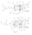
- Fig. 1 shows a cable assembly 100 for securing a person.
- the cable arrangement 100 has a sleeve element 101 with a receiving opening 102 and a cable 110 with an end section 111.
- the end portion 111 is disposed in the receiving opening 102.
- An adhesive 130 is disposed in the receiving opening 102 to provide an adhesive bond between the cable 110 and the sleeve member 101.
- the sleeve member 101 is, for example, a shackle, with which the cable 110 can be attached to any object, such as a fixing element of a climbing wall, building wall or, for example, to a seat belt of a person.
- the sleeve member 101 has, for example, a bore 105 through which a connecting bolt can be inserted.
- the end portion 111 of the cable 110 describes the portion of the rope which projects into the receiving opening 102.
- the end portion 111 of the rope may, for example, have a length of about 100 mm to about 250 mm, in particular about 150 mm to about 200 mm.
- the receiving opening 102 is formed larger than the rope diameter of the cable 110, so that a distance between the cable 110 and the receiving opening 102 of about 0.1 mm to about 0.6 mm, in particular 0.2 mm to about 0.5 mm arises.
- the adhesive 130 can homogeneously and constantly surround the end section 111 of the cable 110, so that a robust adhesive bond is produced between the cable 110 and the sleeve element 101.
- a holding device such as a holding bar, to fix the end portion 111 constantly spaced from the sleeve member 101, in particular while the adhesive is filled and cured.
- a bolt 103 can be guided through the sleeve element 101 and through the cable 110 in the end section 111.
- a first bore and a second bore can be introduced into the sleeve element 101, the first bore and the second bore each extending from the surroundings of the sleeve element 101 into the receiving opening 102.
- the first bore and the second bore are formed in particular around a center line of the sleeve element 101 or around the cable center line 113 in the sleeve element 101.
- a fixing element such as a fixing bolt, can be pushed through the first bore and the second bore so that the cable 110 is spatially fixed in a specific position within the receiving opening 102 between the respective fixing elements.
- the fixing elements may be present in the respective bores until the adhesive 130 has hardened and the cable 110 is spatially fixed accordingly by means of the hardened adhesive 130. After curing of the adhesive 130, the fixing elements can be removed from the holes.
- first bore and / or the second bore can have a thread, so that corresponding threaded screws can be screwed as fixing elements into the first bore and the second bore until the threaded screws carry the rope 110 clamp between each other.
- grub screws can be used as threaded screws.
- the sleeve member 101 in the method step of arranging the end section 111 of the cable 110 in the receiving opening 102, first the cable 110 or its end section 111 can be spatially fixed in the receiving opening 102 by means of the fixing elements. Subsequently, the sleeve member 101 may be heated with the cable 110 in an oven so that a thermosetting adhesive 130 cures in the oven. Subsequently, the sleeve member 101 can be removed together with the cable 110 from the oven and the fixing elements are removed from the respective holes.
- a control mark 104 can be arranged in the receiving opening 102.
- the control mark 104 indicates an ideal level of the adhesive 130 in the receiving opening 102.
- the control mark 104 may be, for example, a groove or a color ring, which is clearly visible from outside the receiving opening 102.
- a further control mark 114 can be arranged on the cable 110, which delimits the end portion 111 between a free end 112 of the cable 110 along the cable center line 113 and the further control mark 114.
- the further control mark 114 may, for example, be a color ring which envelops the cable 110 accordingly.
- a wedge member 204 (See FIG Fig. 2 ) are introduced along the cable centerline 113 to create a widening of the cable 110.
- Fig. 1 can be used as adhesive 130, a thermally curable adhesive 130.
- the receiving opening 102 has a cylindrical
- the end portion 111 of the cable 110 is inserted centrally into the receiving opening 102.
- the space between the end portion 111 and the inner surface of the sleeve member 101 within the receiving opening 102 is filled with the adhesive 130.
- the adhesive 130 By filling the adhesive 130, air within the receiving opening 102 escapes completely.
- the cable assembly 100 is heated in an oven, for example, so that the thermosetting adhesive 130 cures and an adhesive bond is created between the end portion 111 and the sleeve member 101.
- the thermally curable adhesive 130 is exclusively a material connection or a frictional connection between the end portion 111 and the sleeve member 101 created without a positive connection is necessary. Further, it is not necessary to split the cable 110 or réellespreizen to achieve a positive connection.
- the rope 110 may be untreated, except a possible roughening of the surface, are glued to the sleeve member. As a result, the rope 110 does not become mechanically unstable in its structure and is very robust in the cable arrangement 100.
- FIG. 2 shows another exemplary embodiment of the present cable assembly 100.
- the cable assembly 100 in FIG Fig. 2 may have the same features as the cable assembly 100 Fig. 1 exhibit.
- the cable assembly 100 off Fig. 2 also have a bolt 103, not shown, for additional fixation of the cable 110 to the sleeve member 101.
- the receiving opening 102 is formed with a conical profile 203.
- the conical profile 203 is formed such that a first opening cross-section 201 of the receiving opening 102 in the region of the free end 112 of the end portion 111 is greater than a second Opening cross-section 202.
- the second opening cross-section 202 of the receiving opening 101 is along the cable centerline 113 at an opposite end of the free end 112 of the end portion 111 of the rope 110.
- the second opening cross-section 202 at the entrance of the receiving opening 102 is smaller than a first opening cross section 201th inside the receiving opening 102.
- the receiving opening 102 further has a conical profile shape 203.
- the conical profile shape 203 of the receiving opening 102 is formed such that a first opening cross section 201 of the receiving opening 102 in the region of a free end 112 of the end portion 111 of the cable 110 is greater than a second opening cross section 202 of the receiving opening 102 at an opposite the free end 112 of the end portion
- the second opening cross-section 202 at the entrance of the receiving opening 102 is smaller than the first opening cross-section 201 in the interior of the receiving opening 102.
- the adhesive 130 thus forms a plug in the cured state, which is not through the second opening cross-section 202 can be pushed out at the entrance of the receiving opening 102.
- an overflow bore 205 can be formed on the sleeve element 101 in the region of the control mark 104.
- the overflow hole 205 sets the desired level of the adhesive 130 in the receiving opening 102. For example, if too much adhesive 130 is introduced into the receiving opening 102, the excess adhesive 130 flows through the overflow hole 205 addition. For example, during filling of the adhesive 130, the optional passage 106 may be closed.
- the wedge element 204 can further be introduced in the direction of the cable 110. If the end section 111 is already in the receiving opening, then, for example, the wedge element 204 can pass through the Implementation 106 are introduced.
- the wedge member 204 may be driven along the free end 112 of the cable 110 along the cable centerline 113 to create a widening of the rope diameter of the cable 110 at the free end 112. The widening may, for example, be greater than the second opening cross section 202, so that pulling out of the cable 110 from the receiving opening 102, for example in the case of failure of the adhesive connection 130, is prevented.
- the receiving opening 102 has a central axis.
- the cable centerline 113 is coaxial with the central axis of the receiving opening 102, in particular when the cable is inserted.
- the passage 106 is formed, so that the wedge element 204 can be driven along the cable center line 113 into the free end 112 of the end section 111 and a desired expansion arises.
- the cable assembly 100 can be made in a simple manner.
- the following is a brief summary of the simple production process:
- the sleeve member 101 having the receiving bore 102 and the cable 110 having an end portion 111 is provided and the end portion 111 is placed in the receiving opening 102. Before or after the arrangement, the receiving opening 102 is filled with the adhesive 130. After curing of the adhesive 130, an adhesive bond is formed between the cable 110 and the sleeve member 101.
- the wedge member 204 Prior to curing the adhesive 130, the wedge member 204 may be inserted into the free end 112 along the cable centerline 113. Also, prior to curing of the adhesive 130, the bolt 103 may be inserted for additional securement.
- the adhesive 130 is filled up to the control mark 104 in the receiving opening 102. Furthermore, the cable 110 is inserted into the receiving opening 102 until, for example, the further control mark 114 of the cable 110 has reached the entrance of the receiving opening 102. This ensures that the cable 110 is inserted with a sufficiently long end portion 111 in the receiving opening 102 in order to produce a secure adhesive connection.
Landscapes
- Engineering & Computer Science (AREA)
- General Engineering & Computer Science (AREA)
- Mechanical Engineering (AREA)
- Ropes Or Cables (AREA)
- Standing Axle, Rod, Or Tube Structures Coupled By Welding, Adhesion, Or Deposition (AREA)
Abstract
Description
- Die vorliegende Erfindung betrifft eine Seilanordnung zum Sichern einer Person und ein Verfahren zum Herstellen einer Seilanordnung.
- Im Bereich der Arbeitssicherheit und im Klettersport werden Personen beispielsweise an Halteseilen befestigt, um die Personen vor einem Absturz zu sichern. Dabei wird das Halteseil beispielsweise an Verbindungsstücken (z.B. Schäkel) befestigt. Die Verbindungsstücke bilden eine Kopplung des Halteseils mit einem entsprechenden Fixpunkt an einer Gehäusewand oder einer Kletterwand.
- Das Verbindungsstück kann eine Hülse aufweisen, in welcher ein Seilende des Halteseils eingeschoben wird. Anschließend wird mit einer Pressvorrichtung das Hülsenelement zusammengepresst, wodurch wiederum das Seilende in dem Hülsenelement eingepresst wird. Das Hülsenelement wird dadurch plastisch verformt, so dass nach dem Pressvorgang eine Pressverbindung zwischen dem Hülsenelement und dem Seil bestehen bleibt. Je stabiler das Hülsenelement, desto stärker kann eine Pressverbindung ausgebildet werden und desto fester ist das Seil in dem Hülsenelement befestigt.
- Um allerdings ein hochstabiles Hülsenelement plastisch zu verformen, um eine robuste und starken Pressverbindung mit dem Seil herzustellen, sind große Umformkräfte notwendig. Um diese zu erzeugen sind große Pressvorrichtungen notwendig, welche nur schwer transportabel sind. Bei Defekt einer Pressverbindung zwischen dem Seil und dem Hülsenelement ist somit ständig die Pressvorrichtung vor Ort notwendig, um eine neue Pressverbindung zwischen dem Seil und dem Hülsenelement herzustellen. Dies erschwert eine Reparatur der Pressverbindung im Einsatzgebiet, das heißt vor Ort an einer Kletterwand oder an einer Gebäudewand.
- Es ist eine Aufgabe der vorliegenden Erfindung, eine einfache Seilverbindung mit einem Hülsenelement bereitzustellen.
- Diese Aufgabe wird mit einer Seilanordnung zum Sichern einer Person und mit einem Verfahren zum Herstellen einer Seilanordnung gemäß den unabhängigen Ansprüchen gelöst.
- Gemäß eines ersten Aspekts der vorliegenden Erfindung wird eine Seilanordnung zum Sichern einer Person beschrieben. Die Seilanordnung weist ein Hülsenelement mit einer Aufnahmeöffnung, ein Seil mit einem Endabschnitt und ein Klebemittel auf. Der Endabschnitt des Seils ist in der Aufnahmeöffnung angeordnet. Das Klebeelement ist in der Aufnahmeöffnung angeordnet, um eine Klebeverbindung zwischen dem Seil und dem Hülsenelement bereitzustellen.
- Das Hülsenelement kann beispielsweise ein Teil eines Verbindungsstücks, wie z.B. eines Schäkels sein, welcher an einem Sitzgurt oder an einem anderen Sicherungselement variabel angeordnet werden kann.
- Das Seil kann beispielsweise einen runden Querschnitt oder einen bandförmigen Querschnitt aufweisen. Ferner kann das Seil ein Drahtseil sein. Darüber hinaus kann das Seil aus Verbundfasern oder aus Naturfasern bestehen.
- Das Klebemittel ist beispielsweise ein Kleber, welcher während der Herstellungsphase flüssig vorliegt und nach einem Aushärten fest vorliegt. Das Klebemittel kann durch Flächenhaftung, das heißt durch Adhäsion oder durch Kohäsion die Klebeverbindung zwischen dem Seil und dem Hülsenelement bereitstellen. Adhäsion bedeutet, dass das Seil und das Hülsenelement mittels Haftkräften miteinander verbunden sind. Bei der Kohäsion werden chemische Verbindungen zwischen dem Klebstoff und entsprechend dem Hülsenelement und/oder dem Seil hergestellt. Das Klebemittel kann beispielsweise ein Zweikomponentenkleber sein. Bei Zweikomponentenklebstoffen weist eine Komponente Harzmonumere bzw. Binder auf, während die andere Komponente einen Härter aufweist. Alternativ können Einkomponentenkleber, wie zum Beispiel Einkomponenten-Expositharzklebstoff als Klebemittel eingesetzt werden.
- Ferner kann ein Klebemittel eingesetzt werden, welches quellende Eigenschaften bei Trocknung aufweist. Dies bedeutet, dass das Klebemittel im flüssigen Zustand weniger Volumen aufweist als im ausgehärteten Zustand. Mit anderen Worten quillt das Klebemittel während des Aushärtens auf, so dass neben der Klebeverbindung auch eine Pressverbindung zwischen dem Hülsenelement, dem ausgehärteten Klebemittel und dem Seil hergestellt wird.
- Ferner ist das Klebemittel ein thermisch härtendes Klebemittel. Ein thermisch härtendes Klebemittel härtet bei Anwendung einer bestimmten Temperatur, zum Beispiel bei einer Temperatur von über 30°, insbesondere bei einer Temperatur von über 50° oder über 100°, aus. Zudem kann das thermisch härtende Klebemittel ein anaerobes Klebemittel sein, bei welchem eine Härtung auch bei Ausschluss von Luft bzw. Luftsauerstoff, insbesondere bei hoher Temperatur, erzielt wird.
- Die Anwendung eines solchen thermisch härtenden Klebemittels führt dazu, dass der Endabschnitt des Seils in die Aufnahmeöffnung des Hülsenelements eingeführt werden kann, ohne dass Luftspalte oder andere Luftversorgung zum Aushärten des Klebemittels notwendig ist. Mit anderen Worten kann in der Aufnahmeöffnung ausschließlich der Endabschnitt und das Klebemittel eingebracht werden, ohne dass ein Einschluss von Luft zum Aushärten notwendig ist.
- In einer weiteren beispielhaften Ausführungsform ist das Hülsenelement derart ausgebildet, dass die Aufnahmeöffnung ein zylindrisches Profil aufweist. Mit anderen Worten weist die Aufnahmeöffnung gerade kein konisches Profil auf.
- Das Seil kann mit dem Endabschnitt in die Aufnahmeöffnung eingeschoben werden und das Klebemittel bildet eine stoffliche und reibschlüssige Verbindung zwischen dem Endabschnitt des Seils und dem Hülsenelement auf. Das Klebemittel bildet somit insbesondere keine formschlüssige Verbindung aus, bei welcher das Klebemittel beispielsweise in einer keilförmigen Aufnahmeöffnung einen Pfropfen bildet, womit ein Herausziehen des Seils unterbunden wird. Das Hülsenelement mit einer zylindrischen Aufnahmeöffnung kann in einfacher Art und Weise hergestellt werden.
- Das Seil weist im Endabschnitt eine raue Oberfläche auf. Der Endabschnitt des Seils kann dazu (z.B. mechanisch oder chemisch) aufgeraut werden. Anschließend kann das Klebemittel auf die aufgeraute Oberfläche des Seils aufgebracht werden oder direkt in die Aufnahmeöffnung eingefüllt werden und der Endabschnitt in die Aufnahmeöffnung des Hülsenelements eingebracht werden. Wenn als Klebemittel das oben beschriebene thermisch härtende Klebemittel eingesetzt wird, ist ein Lufteinschluss zur Aushärtung in der Aufnahmeöffnung nicht notwendig. Anschließend kann die Seilanordnung beispielsweise in einen Ofen eingelegt werden, so dass das Hülsenelement mit dem Endabschnitt des Seils zur Aushärtung des Klebemittels beheizt wird. Aufgrund des Einsatzes des thermisch aushärtbaren Klebemittels ist keine Luft in der Hülse und keine Bereitstellung von Mikrospalten zum Bereitstellen von Luft notwendig.
- Mit der Seilanordnung gemäß der vorliegenden Erfindung kann schnell und zuverlässig eine Seilverbindung zwischen einem Seil und einem Hülsenelement hergestellt werden, ohne dass schwer zu transportierende Herstellvorrichtungen, wie beispielsweise Pressvorrichtungen, zum Deformieren des Hülsenelements mittransportiert werden müssen. Am Einsatzort kann schnell und einfach das Klebemittel in die Aufnahmeöffnung eingefüllt werden und das Seil in die Aufnahmeöffnung hinein geschoben werden. Nach Aushärten des Klebemittels ist eine feste und sichere Seilverbindung geschaffen, ohne dass schwere und teure Herstellvorrichtungen mitgeführt werden müssen. Somit kann eine Seilanordnung auch schnell am Einsatzort repariert werden. Beispielsweise kann bei Riss des Seils das Restseil und das Klebemittel mittels eines Lösungsmittels oder mittels Auskratzens aus der Aufnahmeöffnung des Hülsenelements entfernt werden. Anschließend kann ein neuer Endabschnitt des Seils in die Aufnahmeöffnung eingeführt werden und mittels eines Klebemittels verklebt werden.
- In einer weiteren beispielhaften Ausführungsform weist die Aufnahmeöffnung ein konisches Profil auf.
- In einer weiteren beispielhaften Ausführungsform ist das konische Profil der Aufnahmeöffnung derart ausgebildet, dass ein erster Öffnungsquerschnitt der Aufnahmeöffnung im Bereich eines freien Endes des Endabschnitts des Seils größer ist als ein zweiter Öffnungsquerschnitt der Aufnahmeöffnung an einem gegenüberliegenden dem freien Ende des Endabschnitts liegenden Bereich des Endabschnitts des Seils. Mit anderen Worten ist der zweite Öffnungsquerschnitt an dem Eingang der Aufnahmeöffnung kleiner als der erste Öffnungsquerschnitt im Inneren der Aufnahmeöffnung. Der Klebstoff in der Aufnahmeöffnung ist nach dem Aushärten entsprechend dem konischen Profils konisch bzw. keilförmig ausgebildet. Das Klebemittel bildet im ausgehärteten Zustand somit einen Pfropfen, welcher nicht durch den zweiten Öffnungsquerschnitt am Eingang der Aufnahmeöffnung hinausgeschoben werden kann. Somit wird eine festere Verbindung zwischen dem Seil, dem ausgehärteten Klebemittel und dem Hülsenelement geschaffen.
- Gemäß einer weiteren beispielhaften Ausführungsform weist die Seilanordnung ferner einen Bolzen auf, welcher derart angeordnet ist, dass der Bolzen durch das Hülsenelement und durch den Endabschnitt des Seils geführt ist. Durch Einsatz des Bolzens wird eine zusätzliche Sicherheitsvorkehrung eingeführt. Der Bolzen wird sozusagen durch die äußere Wandung des Hülsenelements und durch das Seil hindurchgesteckt. Somit bildet neben dem Klebemittel der Bolzen eine zusätzliche Befestigung zwischen dem Seil und dem Hülsenelement.
- Gemäß einer weiteren beispielhaften Ausführungsform weist die Seilanordnung ein Keilelement auf, welches von einem freien Ende des Endabschnitts des Seils entlang einer Seilmittellinie des Seils in das Seil derart eingetrieben ist und hineinverläuft, dass in einem Bereich des Endabschnitts eine Aufweitung eines Durchmessers des Seils ausgebildet ist. Wird das Keilelement entlang der Seilmittellinie von dem freien Ende in das Seil hineingetrieben, so entsteht ein Wulst bzw. ein konischer Endabschnitt des Seils am freien Ende. Insbesondere kann der Durchmesser am Endabschnitt mittels des Keilelements derart aufgeweitet werden, dass beispielsweise der Durchmesser des Seils in dem aufgeweiteten Bereich größer ist als der zweite Öffnungsquerschnitt der Aufnahmeöffnung. Somit kann ein Lösen des Seils bzw. ein Herausschieben des Seils aus der Aufnahmeöffnung verhindert werden.
- Beispielsweise kann das Seil in die Aufnahmeöffnung, welche eine konische Profilform aufweist, zunächst hineingeschoben werden. Anschließend kann das Seil in der Aufnahmeöffnung wie gewünscht positioniert werden. Vor oder nach dem Einbringen des Klebemittels in die Aufnahmeöffnung kann das Keilelement durch eine weitere Öffnung im Hülsenelement hindurchgeschoben werden und mittels Drückens oder Hämmerns in das freie Ende des Seils eingetrieben werden, um das Seil aufzuweiten.
- Gemäß einer weiteren beispielhaften Ausführungsform sind die Aufnahmeöffnung und das Seil derart ausgebildet, dass zwischen dem Endabschnitt des Seils und dem Hülsenelement in der Aufnahmeöffnung ein Spalt ausgebildet ist. Der Spalt kann beispielsweise einen Abstand zwischen dem Endabschnitt und dem Hülsenelement von ungefähr 0,2 mm bis ungefähr 0,5 mm aufweisen. Somit wird sichergestellt, dass ausreichend Raum gebildet wird, in welchem das Klebemittel einführbar ist. Insbesondere wird dadurch sichergestellt, dass das Klebemittel fast oder völlig das Seil umgibt, so dass eine feste Klebeverbindung und somit eine robuste Seilanordnung bereitstellbar ist.
- Gemäß einer weiteren beispielhaften Ausführungsform weist das Hülsenelement in der Aufnahmeöffnung eine Kontrollmarkierung auf, welche die Befüllmenge des Klebemittels in der Aufnahmeöffnung angibt. Die Kontrollmarkierung kann beispielsweise mittels einer Rille oder mit einer farblichen Markierung in der Aufnahmeöffnung angeordnet werden. Alternativ oder zusätzlich kann die Kontrollmarkierung mittels einer Überlaufbohrung ausgebildet werden, welche in der Wandung des Hülsenelements ausgebildet ist und welche das innere Volumen der Aufnahmeöffnung mit der Umgebung verbindet. Wird das Klebemittel in einem flüssigen Zustand in die Aufnahmeöffnung eingebracht, so tritt das Klebemittel durch die Überlaufbohrung aus, wenn ein gewünschter Füllstand des Klebemittels in der Aufnahmeöffnung erreicht ist.
- Gemäß einer weiteren beispielhaften Ausführungsform weist der Endabschnitt des Seils eine weitere Kontrollmarkierung auf, welche die Einschubtiefe des Endabschnitts in die Aufnahmeöffnung angibt. Die weitere Kontrollmarkierung kann beispielsweise eine farbliche Markierung an dem Seil sein. Ferner kann die weitere Kontrollmarkierung ein Ringelement darstellen, welches an dem Seil an einer entsprechenden Position angeordnet ist.
- Gemäß einer weiteren beispielhaften Ausführungsform weist das Hülsenelement in der Aufnahmeöffnung eine aufgeraute Oberfläche, insbesondere eine geriffelte oder beschichtete Oberfläche, auf. Der Reibkoeffizienten zwischen dem Klebemittel und der Aufnahmeöffnung wird mittels der aufgerauten Oberfläche des Hülsenelements in der Aufnahmeöffnung erhöht, sodass eine stärker haftende Klebeverbindung ausgebildet wird.
- Die aufgeraute Oberfläche wird insbesondere mittels einer Profilierung, wie beispielsweise einem Gewinde (bzw. einer Gewinderiffelung), geschaffen.
- Gemäß eines weiteren Aspekts der vorliegenden Erfindung wird ein Verfahren zum Herstellen einer Seilanordnung beschrieben. Zunächst werden ein Hülsenelement mit einer Aufnahmeöffnung und ein Seil mit einem Endabschnitt bereitgestellt. Anschließend wird die Aufnahmeöffnung mit einem Klebemittel befüllt und der Endabschnitt des Seils in der Aufnahmeöffnung angeordnet, so dass eine Klebeverbindung zwischen dem Seil und dem Hülsenelement erzeugt wird. Alternativ kann der Endabschnitt vor dem Befüllen der Aufnahmeöffnung mit einem Klebemittel in der Aufnahmeöffnung angeordnet werden.
- Es wird darauf hingewiesen, dass die hier beschriebenen Ausführungsformen lediglich eine beschränkte Auswahl an möglichen Ausführungsvarianten der
- Erfindung darstellen. So ist es möglich, die Merkmale einzelner Ausführungsformen in geeigneter Weise miteinander zu kombinieren, so dass für den Fachmann mit den hier expliziten Ausführungsvarianten eine Vielzahl von verschiedenen Ausführungsformen als offensichtlich offenbart anzusehen sind. Insbesondere sind einige Ausführungsformen der Erfindung mit Vorrichtungsansprüchen und andere Ausführungsformen der Erfindung mit Verfahrensansprüchen beschrieben. Dem Fachmann wird jedoch bei der Lektüre dieser Anmeldung sofort klar werden, dass, sofern nicht explizit anders angegeben, zusätzlich zu einer Kombination von Merkmalen, die zu einem Typ von Erfindungsgegenstand gehören, auch eine beliebige Kombination von Merkmalen möglich ist, die zu unterschiedlichen Typen von Erfindungsgegenständen gehören.
- Im Folgenden werden zur weiteren Erläuterung und zum besseren Verständnis der vorliegenden Erfindung Ausführungsbeispiele unter Bezugnahme auf die beigefügten Figuren näher beschrieben. Es zeigen:
-
Fig. 1 eine schematische Darstellung einer Seilanordnung gemäß einer beispielhaften Ausführungsform der vorliegenden Erfindung; und -
Fig. 2 eine schematische Darstellung einer Seilanordnung gemäß einer beispielhaften Ausführungsform der vorliegenden Erfindung, wobei die Aufnahmeöffnung eine konische Profilform aufweist. - Gleiche oder ähnliche Komponenten sind in den Figuren mit gleichen Bezugsziffern versehen. Die Darstellungen in den Figuren sind schematisch und nicht maßstäblich.
-
Fig. 1 zeigt eine Seilanordnung 100 zum Sichern einer Person. Die Seilanordnung 100 weist ein Hülsenelement 101 mit einer Aufnahmeöffnung 102 und ein Seil 110 mit einem Endabschnitt 111 auf. Der Endabschnitt 111 ist in der Aufnahmeöffnung 102 angeordnet. Ein Klebemittel 130 ist in der Aufnahmeöffnung 102 angeordnet, um eine Klebeverbindung zwischen dem Seil 110 und dem Hülsenelement 101 bereitzustellen. - Das Hülsenelement 101 ist beispielsweise ein Schäkel, mit welchem das Seil 110 an einem beliebigen Gegenstand, wie beispielsweise an einem Fixierungselement einer Kletterwand, Gebäudewand oder beispielsweise an einen Sitzgurt einer Person befestigt werden kann. Das Hülsenelement 101 weist dazu zum Beispiel eine Bohrung 105 auf, durch welche ein Verbindungsbolzen eingeführt werden kann.
- Der Endabschnitt 111 des Seils 110 beschreibt den Abschnitt des Seils, welcher in die Aufnahmeöffnung 102 hineinragt. Der Endabschnitt 111 des Seils kann beispielsweise eine Länge von ungefähr 100 mm bis ungefähr 250 mm, insbesondere ungefähr 150 mm bis ungefähr 200 mm, aufweisen. Ferner ist die Aufnahmeöffnung 102 größer als der Seildurchmesser des Seils 110 ausgebildet, so dass ein Abstand zwischen dem Seil 110 und der Aufnahmeöffnung 102 von ca. 0,1 mm bis ungefähr 0,6 mm, insbesondere 0,2 mm bis ungefähr 0,5 mm entsteht. Dadurch kann das Klebemittel 130 homogen und konstant den Endabschnitt 111 des Seils 110 umgeben, so dass eine robuste Klebeverbindung zwischen dem Seil 110 und dem Hülsenelement 101 hergestellt wird. Zur Positionierung des Endabschnitts 111 in der Aufnahmeöffnung 102 kann durch eine Durchführung 106 im Hülsenelement 101 eine Haltevorrichtung, wie beispielsweise ein Haltestab, durchgeführt werden, um den Endabschnitt 111 konstant beabstandet zu dem Hülsenelement 101 zu fixieren, insbesondere während das Klebemittel eingefüllt wird und ausgehärtet wird.
- Zur zusätzlichen Sicherung der Verbindung zwischen dem Seil 110 und dem Hülsenelement 101 kann ein Bolzen 103 durch das Hülsenelement 101 und durch das Seil 110 im Endabschnitt 111 geführt werden.
- Insbesondere kann in das Hülsenelement 101 eine erste Bohrung und eine zweite Bohrung eingebracht werden, wobei sich die erste Bohrung und die zweite Bohrung jeweils von der Umgebung des Hülsenelements 101 in die Aufnahmeöffnung 102 erstrecken. Die erste Bohrung und die zweite Bohrung sind dabei insbesondere um eine Mittellinie des Hülsenelements 101 bzw. um die Seilmittellinie 113 beanstandet zueinander in dem Hülsenelement 101 ausgebildet. Durch die erste Bohrung und die zweite Bohrung kann jeweils ein Fixierungselement, wie beispielsweise ein Fixierungsbolzen, hindurchgeschoben werden, so dass das Seil 110 in einer bestimmten Position innerhalb der Aufnahmeöffnung 102 zwischen den jeweiligen Fixierungselementen räumlich fixiert vorliegt. Die Fixierungselemente können in den jeweiligen Bohrungen vorliegen, bis das Klebemittel 130 ausgehärtet ist und das Seil 110 entsprechend mittels des ausgehärteten Klebemittels 130 räumlich fixiert ist. Nach dem Aushärten des Klebemittels 130 können die Fixierungselemente aus den Bohrungen entfernt werden.
- In einer weiteren beispielhaften Ausführungsform kann die erste Bohrung und/oder die zweite Bohrung ein Gewinde aufweisen, so dass entsprechende Gewindeschrauben als Fixierungselemente in die erste Bohrung und die zweite Bohrung eingeschraubt werden können bis die Gewindeschrauben das Seil 110 zwischen einander einspannen. Bevorzugt können als Gewindeschrauben beispielsweise sogenannte Madenschrauben verwendet werden.
- In einer beispielhaften Ausführungsform des Herstellerverfahrens kann in dem Verfahrensschritt Anordnen des Endabschnitts 111 des Seils 110 in der Aufnahmeöffnung 102 zunächst das Seil 110 bzw. dessen Endabschnitt 111 in der Aufnahmeöffnung 102 mittels der Fixierungselemente räumlich fixiert werden. Anschließend kann das Hülsenelement 101 mit dem Seil 110 in einem Ofen erwärmt werden, so dass ein thermisch aushärtendes Klebemittel 130 in dem Ofen aushärtet. Anschließend kann das Hülsenelement 101 mitsamt dem Seil 110 aus dem Ofen entnommen werden und die Fixierungselemente aus den jeweiligen Bohrungen entnommen werden.
- Ferner kann eine Kontrollmarkierung 104 in der Aufnahmeöffnung 102 angeordnet werden. Die Kontrollmarkierung 104 zeigt einen idealen Füllstand des Klebemittels 130 in der Aufnahmeöffnung 102 an. Die Kontrollmarkierung 104 kann beispielsweise eine Rille oder ein Farbring sein, welcher von außerhalb der Aufnahmeöffnung 102 gut wahrnehmbar ist.
- Entsprechend kann an dem Seil 110 eine weitere Kontrollmarkierung 114 angeordnet sein, welche den Endabschnitt 111 zwischen einem freien Ende 112 des Seils 110 entlang der Seilmittellinie 113 und der weiteren Kontrollmarkierung 114 eingrenzt. Die weitere Kontrollmarkierung 114 kann beispielsweise ein Farbring sein, welcher das Seil 110 entsprechend umhüllt.
- Ferner kann an dem freien Ende 112 des Seils 110 ein Keilelement 204 (Siehe
Fig. 2 ) entlang der Seilmittellinie 113 eingebracht werden, um eine Aufweitung des Seils 110 zu erzeugen. - In
Fig. 1 kann als Klebemittel 130 ein thermisch aushärtbares Klebemittel 130 eingesetzt werden. Die Aufnahmeöffnung 102 weist eine zylindrische - Profilform auf. Der Endabschnitt 111 des Seils 110 ist mittig in die Aufnahmeöffnung 102 eingeschoben. Der Raum zwischen dem Endabschnitt 111 und der Innenfläche des Hülsenelements 101 innerhalb der Aufnahmeöffnung 102 wird mit dem Klebemittel 130 gefüllt. Durch das Einfüllen des Klebemittels 130 entweicht Luft innerhalb der Aufnahmeöffnung 102 vollständig.
- Zur Aushärtung des thermisch aushärtbaren Klebemittels 130 wird die Seilanordnung 100 beispielsweise in einem Ofen erhitzt so dass das thermisch aushärtende Klebemittel 130 aushärtet und eine Klebeverbindung zwischen dem Endabschnitt 111 und dem Hülsenelement 101 erzeugt wird. Mittels des thermisch aushärtbaren Klebemittels 130 wird ausschließlich eine stoffliche Verbindung bzw. eine reibschlüssige Verbindung zwischen dem Endabschnitt 111 und dem Hülsenelement 101 geschaffen, ohne dass eine formschlüssige Verbindung notwendig ist. Ferner ist es nicht notwendig, das Seil 110 aufzuspalten bzw. aufzuspreizen, um eine formschlüssige Verbindung zu erzielen. Das Seil 110 kann unbehandelt, außer einer möglichen Aufrauhung der Oberfläche, mit dem Hülsenelement verklebt werden. Damit wird das Seil 110 in seiner Struktur nicht mechanisch instabil und liegt in der Seilanordnung 100 sehr robust vor.
-
Fig. 2 zeigt eine weitere beispielhafte Ausführungsform der vorliegenden Seilanordnung 100. Die Seilanordnung 100 inFig. 2 kann dieselben Merkmale wie die Seilanordnung 100 ausFig. 1 aufweisen. So kann die Seilanordnung 100 ausFig. 2 ebenfalls einen nicht dargestellten Bolzen 103 zur zusätzlichen Fixierung des Seils 110 an dem Hülsenelement 101 aufweisen. - In
Fig. 2 ist die Aufnahmeöffnung 102 mit einem konischen Profil 203 ausgebildet. Insbesondere ist das konische Profil 203 derart ausgebildet, dass ein erster Öffnungsquerschnitt 201 der Aufnahmeöffnung 102 im Bereich des freien Endes 112 des Endabschnitts 111 größer ist als ein zweiter Öffnungsquerschnitt 202. Der zweite Öffnungsquerschnitt 202 der Aufnahmeöffnung 101 liegt entlang der Seilmittellinie 113 an einem zu dem freien Ende 112 gegenüberliegenden Ende des Endabschnitts 111 des Seils 110. Mit anderen Worten ist der zweite Öffnungsquerschnitt 202 am Eingang der Aufnahmeöffnung 102 kleiner als ein erster Öffnungsquerschnitt 201 im Inneren der Aufnahmeöffnung 102. - Die Aufnahmeöffnung 102 weist ferner eine konische Profilform 203 auf. Die konische Profilform 203 der Aufnahmeöffnung 102 ist derart ausgebildet, dass ein erster Öffnungsquerschnitt 201 der Aufnahmeöffnung 102 im Bereich eines freien Endes 112 des Endabschnitts 111 des Seils 110 größer ist als ein zweiter Öffnungsquerschnitt 202 der Aufnahmeöffnung 102 an einem gegenüberliegenden dem freien Ende 112 des Endabschnitts 111 liegenden Bereich des Endabschnitts des Seils 110. Mit anderen Worten ist der zweite Öffnungsquerschnitt 202 an dem Eingang der Aufnahmeöffnung 102 kleiner als der erste Öffnungsquerschnitt 201 im Inneren der Aufnahmeöffnung 102. Das Klebemittel 130 bildet im ausgehärteten Zustand somit einen Pfropfen, welcher nicht durch den zweiten Öffnungsquerschnitt 202 am Eingang der Aufnahmeöffnung 102 hinausgeschoben werden kann.
- Ferner kann an dem Hülsenelement 101 im Bereich der Kontrollmarkierung 104 eine Überlaufbohrung 205 ausgebildet werden. Die Überlaufbohrung 205 stellt den gewünschten Füllstand des Klebemittels 130 in der Aufnahmeöffnung 102 ein. Wird beispielsweise zu viel Klebemittel 130 in die Aufnahmeöffnung 102 eingebracht, so fließt das überschüssige Klebemittel 130 durch die Überlaufbohrung 205 hinaus. Während des Einfüllens des Klebemittels 130 kann beispielsweise die optionale Durchführung 106 geschlossen werden.
- Durch die Durchführung 106 kann ferner das Keilelement 204 in Richtung Seil 110 eingebracht werden. Befindet sich der Endabschnitt 111 bereits in der Aufnahmeöffnung, so kann beispielsweise das Keilelement 204 durch die Durchführung 106 eingebracht werden. Das Keilelement 204 kann insbesondere an dem freien Ende 112 des Seils 110 entlang der Seilmittellinie 113 eingetrieben werden, um eine Aufweitung des Seildurchmessers des Seils 110 am freien Ende 112 zu erzeugen. Die Aufweitung kann beispielsweise größer als der zweite Öffnungsquerschnitt 202 sein, so dass ein Herausziehen des Seils 110 aus der Aufnahmeöffnung 102, beispielsweise bei Versagen der Klebeverbindung 130, verhindert wird.
- Die Aufnahmeöffnung 102 weist eine Mittelachse auf. Die Seilmittellinie 113 ist insbesondere bei eingeführtem Seil koaxial mit der Mittelachse der Aufnahmeöffnung 102. Entlang einer Verlängerung der Mittelachse der Aufnahmeöffnung 102 wird die Durchführung 106 ausgebildet, so dass das Keilelement 204 entlang der Seilmittellinie 113 in das freie Ende 112 des Endabschnitts 111 eingetrieben werden kann und eine gewünschte Aufweitung entsteht.
- Wie in
Fig. 1 und Fig. 2 dargestellt, kann in einfacher Art und Weise die Seilanordnung 100 hergestellt werden. Im Folgenden wird das einfache Herstellverfahren kurz zusammengefasst: - Das Hülsenelement 101 mit der Aufnahmebohrung 102 und das Seil 110 mit einem Endabschnitt 111 wird bereitgestellt und der Endabschnitt 111 wird in der Aufnahmeöffnung 102 platziert. Vor oder nach dem Anordnen wird die Aufnahmeöffnung 102 mit dem Klebemittel 130 befüllt. Nach dem Aushärten des Klebemittels 130 entsteht eine Klebeverbindung zwischen dem Seil 110 und dem Hülsenelement 101.
- Vor dem Aushärten des Klebemittels 130 kann das Keilelement 204 in das freie Ende 112 entlang der Seilmittellinie 113 eingebracht werden. Ebenfalls vor dem Aushärten des Klebemittels 130 kann zur zusätzlichen Sicherung der Bolzen 103 eingeführt werden.
- Das Klebemittel 130 wird bis zu der Kontrollmarkierung 104 in die Aufnahmeöffnung 102 eingefüllt. Ferner wird das Seil 110 in die Aufnahmeöffnung 102 eingeschoben, bis beispielsweise die weitere Kontrollmarkierung 114 des Seils 110 den Eingang der Aufnahmeöffnung 102 erreicht hat. Damit wird sichergestellt, dass das Seil 110 mit einem ausreichend langen Endabschnitt 111 in der Aufnahmeöffnung 102 eingeführt ist, um eine sichere Klebeverbindung herzustellen.
- Ergänzend ist darauf hinzuweisen, dass "umfassend" keine anderen Elemente oder Schritte ausschließt und "eine" oder "ein" keine Vielzahl ausschließt. Ferner sei darauf hingewiesen, dass Merkmale oder Schritte, die mit Verweis auf eines der obigen Ausführungsbeispiele beschrieben worden ist, auch in Kombination mit anderen Merkmalen oder Schritten anderer oben beschriebener Ausführungsbeispiele verwendet werden können. Bezugszeichen in den Ansprüchen sind nicht als Einschränkung anzusehen.
-
- 100
- Seilanordnung
- 101
- Hülsenelement
- 102
- Aufnahmeöffnung
- 103
- Bolzen
- 104
- Kontrollmarkierung
- 105
- Bohrung
- 106
- Durchführung
- 110
- Seil
- 111
- Endabschnitt
- 112
- freies Ende
- 113
- Seilmittellinie
- 114
- weitere Kontrollmarkierung
- 130
- Klebemittel
- 201
- erster Öffnungsquerschnitt
- 202
- zweiter Öffnungsquerschnitt
- 203
- konische Profilform
- 204
- Keilelement
- 205
- Überlaufbohrung
Claims (15)
- Seilanordnung (100) zum Sichern einer Person, aufweisend
ein Hülsenelement (101) mit einer Aufnahmeöffnung (102),
ein Seil (110) mit einem Endabschnitt (111),
wobei der Endabschnitt (111) in der Aufnahmeöffnung (102) angeordnet ist,
ein Klebemittel (130), welches in der Aufnahmeöffnung (102) angeordnet ist, um eine Klebeverbindung zwischen dem Seil (110) und dem Hülsenelement (101) bereitzustellen. - Seilanordnung (100) gemäß Anspruch 1,
wobei die Aufnahmeöffnung (102) ein zylinderförmiges Profil (203) aufweist. - Seilanordnung (100) gemäß Anspruch 1,
wobei die Aufnahmeöffnung (102) ein konisches Profil (203) aufweist. - Seilanordnung (100) gemäß Anspruch 3,
wobei das konische Profil (203) der Aufnahmeöffnung (102) derart ausgebildet ist, dass ein erster Öffnungsquerschnitt (201) der Aufnahmeöffnung (102) im Bereich eines freien Endes (112) des Endabschnitts (111) des Seils (110) größer ist als ein zweiter Öffnungsquerschnitt (202) der Aufnahmeöffnung (102) an einem gegenüber dem freien Ende (112) des Endabschnitts (111) liegendem Bereich des Endabschnitts (111) des Seils (110). - Seilanordnung (100) gemäß einem der Ansprüche 1 bis 4, ferner aufweisend
einen Bolzen (103), welcher derart angeordnet ist, dass der Bolzen (103) durch das Hülsenelement (101) und durch den Endabschnitt (111) des Seils (110) geführt ist. - Seilanordnung (100) gemäß einem der Ansprüche 1 bis 5, ferner aufweisend
ein Keilelement, welches von einem freien Ende (112) des Endabschnitts (111) entlang einer Seilmittellinie (113) des Seils (110) in das Seil (110) derart hinein verläuft, dass in einem Bereich des Endabschnitts (111) eine Aufweitung eines Durchmessers des Seils (110) ausgebildet ist. - Seilanordnung (100) gemäß einem der Ansprüche 1 bis 6,
wobei das Klebemittel (130) einen Zwei-Komponenten-Kleber und/oder ein Harz aufweist. - Seilanordnung (100) gemäß einem der Ansprüche 1 bis 7,
wobei das Klebemittel (130) ein thermisch aushärtendes Klebemittel aufweist. - Seilanordnung (100) gemäß einem der Ansprüche 1 bis 8,
wobei die Aufnahmeöffnung (102) und das Seil (110) derart ausgebildet sind, dass zwischen dem Endabschnitt (111) des Seils (110) und dem Hülsenelement (101) in der Aufnahmeöffnung (102) ein Spalt ausgebildet ist, wobei der Spalt insbesondere einen Abstand zwischen Endabschnitt (111) und Hülsenelement (101) von 0,2 mm bis 0,5 mm aufweist. - Seilanordnung (100) gemäß einem der Ansprüche 1 bis 9,
wobei das Hülsenelement (101) in der Aufnahmeöffnung (102) eine Kontrollmarkierung (104) aufweist, welche die Befüllmenge des Klebemittels (130) in der Aufnahmeöffnung (102) angibt. - Seilanordnung (100) gemäß einem der Ansprüche 1 bis 10,
wobei das Hülsenelement (101) eine erste Bohrung und eine zweite Bohrung aufweist,
wobei sich die erste Bohrung und die zweite Bohrung von der Umgebung des Hülsenelements (101) in die Aufnahmeöffnung (102) erstrecken,
wobei die erste Bohrung und die zweite Bohrung voneinander beanstandet sind,
wobei die erste Bohrung und die zweite Bohrung derart ausgebildet sind, dass durch die erste Bohrung und die zweite Bohrung jeweils ein Fixierungselement hindurchschiebbar sind, so dass der Endabschnitt (111) des Seils (110) in einer vorbestimmten Position innerhalb der Aufnahmeöffnung (102) zwischen den jeweiligen Fixierungselementen räumlich fixierbar ist. - Seilanordnung (100) gemäß einem der Ansprüche 1 bis 11,
wobei der Endabschnitt (111) des Seils (110) eine weitere Kontrollmarkierung (114) aufweist, welche die Einschubtiefe des Endabschnitts (111) in die Aufnahmeöffnung (102) angibt. - Seilanordnung (100) gemäß einem der Ansprüche 1 bis 12,
wobei das Hülsenelement (101) in der Aufnahmeöffnung (102) eine aufgeraute Oberfläche, insbesondere eine geriffelte oder beschichtete Oberfläche, aufweist. - Verfahren zum Herstellen einer Seilanordnung (100), das Verfahren aufweisend
Bereitstellen eines Hülsenelements (101) mit einer Aufnahmeöffnung (102),
Bereitstellen eines Seils (110) mit einem Endabschnitt (111),
Befüllen der Aufnahmeöffnung (102) mit einem Klebemittel (130), und Anordnen des Endabschnitts (111) in der Aufnahmeöffnung (102), so dass eine Klebeverbindung zwischen dem Seil (110) und dem Hülsenelement (101) erzeugt wird. - Verfahren gemäß Anspruch 14,
wobei das Klebemittel (130) ein thermisch aushärtendes Klebemittel aufweist, wobei das Verfahren ferner aufweist
Erwärmen des Endabschnitts (111) in der Aufnahmeöffnung (102), sodass das thermisch aushärtende Klebemittel aushärtet.
Applications Claiming Priority (1)
| Application Number | Priority Date | Filing Date | Title |
|---|---|---|---|
| DE201210212641 DE102012212641A1 (de) | 2012-07-18 | 2012-07-18 | Klebeverbindung für ein Seil |
Publications (3)
| Publication Number | Publication Date |
|---|---|
| EP2687751A2 true EP2687751A2 (de) | 2014-01-22 |
| EP2687751A3 EP2687751A3 (de) | 2014-12-10 |
| EP2687751B1 EP2687751B1 (de) | 2017-03-29 |
Family
ID=48803427
Family Applications (1)
| Application Number | Title | Priority Date | Filing Date |
|---|---|---|---|
| EP13177115.6A Not-in-force EP2687751B1 (de) | 2012-07-18 | 2013-07-18 | Klebeverbindung für ein Seil |
Country Status (2)
| Country | Link |
|---|---|
| EP (1) | EP2687751B1 (de) |
| DE (1) | DE102012212641A1 (de) |
Cited By (3)
| Publication number | Priority date | Publication date | Assignee | Title |
|---|---|---|---|---|
| US10189678B2 (en) | 2017-04-11 | 2019-01-29 | Thyssenkrupp Elevator Ag | Elevator strip bonded end termination |
| US10808799B2 (en) * | 2016-09-23 | 2020-10-20 | Bright Technologies, Llc | Inverted injection method of affixing a termination to a tensile member |
| CN114808499A (zh) * | 2022-04-21 | 2022-07-29 | 李文娟 | 钢丝绳接头及其连接方法 |
Family Cites Families (10)
| Publication number | Priority date | Publication date | Assignee | Title |
|---|---|---|---|---|
| DE1103694B (de) * | 1940-10-24 | 1961-03-30 | Vorbrueggen Vofa Werk | Endverbindung von eine Hanfseele aufweisenden Drahtseilen mit starren Endstuecken |
| AT222721B (de) * | 1960-06-15 | 1962-08-10 | Mosdorfer K G Weiz | Verfahren zum Abspannen von Leiterseilen od. dgl. |
| GB1193185A (en) * | 1967-05-30 | 1970-05-28 | Dow Chemical Co | Method and Apparatus for Attaching Load Bearing Members to Low Strength Bodies. |
| JPS63120941A (ja) * | 1986-11-10 | 1988-05-25 | Meito Denki Koji Kk | 線条体の端末部の構造 |
| US4955750A (en) * | 1989-09-05 | 1990-09-11 | Leo Goran | Rope fastener |
| IT243925Y1 (it) * | 1998-04-08 | 2002-03-06 | Metalbuttons S P A | Struttura di fermacorda particolarmente per capi di abbigliamentoe simili |
| DE10305382A1 (de) * | 2002-02-12 | 2003-08-14 | Jakob Ag Trubschachen | Seilendverbindung sowie Verfahren zu deren Herstellung |
| DE202007005911U1 (de) * | 2007-04-23 | 2007-06-28 | Teufelberger Ges.M.B.H. | Endteil für ein textiles Forstseil |
| EP2171307A4 (de) * | 2007-05-19 | 2011-05-04 | Samson Rope Technologies | Verbundseilstrukturen und -systeme und verfahren zum abschliessen von verbundseilstrukturen |
| GB0800782D0 (en) * | 2008-01-17 | 2008-02-27 | Mackay Roy | Ferrule fixture |
-
2012
- 2012-07-18 DE DE201210212641 patent/DE102012212641A1/de not_active Ceased
-
2013
- 2013-07-18 EP EP13177115.6A patent/EP2687751B1/de not_active Not-in-force
Non-Patent Citations (1)
| Title |
|---|
| None |
Cited By (5)
| Publication number | Priority date | Publication date | Assignee | Title |
|---|---|---|---|---|
| US10808799B2 (en) * | 2016-09-23 | 2020-10-20 | Bright Technologies, Llc | Inverted injection method of affixing a termination to a tensile member |
| US12123476B2 (en) * | 2016-09-23 | 2024-10-22 | Richard V. Campbell | Inverted injection method of affixing a termination to a tensile member |
| US10189678B2 (en) | 2017-04-11 | 2019-01-29 | Thyssenkrupp Elevator Ag | Elevator strip bonded end termination |
| CN114808499A (zh) * | 2022-04-21 | 2022-07-29 | 李文娟 | 钢丝绳接头及其连接方法 |
| CN114808499B (zh) * | 2022-04-21 | 2023-11-10 | 李文娟 | 钢丝绳接头及其连接方法 |
Also Published As
| Publication number | Publication date |
|---|---|
| DE102012212641A1 (de) | 2014-03-06 |
| EP2687751A3 (de) | 2014-12-10 |
| EP2687751B1 (de) | 2017-03-29 |
Similar Documents
| Publication | Publication Date | Title |
|---|---|---|
| DE3229470C2 (de) | Tunnelauskleidungssegment mit Verriegelungselementen | |
| DE19929057A1 (de) | Fahrzeugtragstruktur und Verfahren zu deren Herstellung | |
| EP3132506A1 (de) | Kabelabgang | |
| DE102007040451A1 (de) | Vorrichtung und Verfahren zur Reparatur einer Rohrleitung | |
| EP2687751B1 (de) | Klebeverbindung für ein Seil | |
| DE102016117435A1 (de) | Bowdenzugabdichtung für Schlossmodul | |
| EP2631392A1 (de) | Vorrichtung zur Krafteinleitung in Zugglieder aus faserverstärkten Kunststoff-Flachbandlamellen | |
| DE102007000278B3 (de) | Vorrichtung zum Verschalen einer Öffnung in einem Bauteil | |
| WO2013021017A1 (de) | Elektrische vorrichtung mit dichtelement, dichtelement für eine elektrische vorrichtung und verfahren zum abdichten eines gehäuses | |
| DE202016100068U1 (de) | Kupplung für die Verbindung eines Zug-/Druckelements mit einem Führungselement | |
| EP0397168A2 (de) | Kryostat | |
| DE19645467A1 (de) | Vorrichtung zur Krafteinleitung | |
| DE3138610C2 (de) | Einrichtung zur haltbaren Befestigung von Gegenständen in Bohrlöchern | |
| EP3135861B1 (de) | Befestigungsvorrichtung | |
| DE19958375C2 (de) | Vorrichtung zur Krafteinleitung und Verfahren zur Verbindung von inkompatiblen Werkstoffen | |
| DE2756969B2 (de) | Rohrförmige Welle mit Endverbindungsstück und Verfahren zur Herstellung der Verbindung | |
| DE102004020118A1 (de) | Anker zur Befestigung einer plattenförmigen Außenschale an einem Mauerwerk, sowie Verfahren zur Montage einer plattenförmigen Außenschale an einem Mauerwerk | |
| DE102008041928A1 (de) | Anker zur Injektionsbefestigung | |
| DE102012001943A1 (de) | Verfahren zum Herstellen eines rohrförmigen rotationssymmetrischen Kfz-Fahrwerkbauteils wie einer Kolbenstange, und gebaute Kolbenstange | |
| DE102007030935B4 (de) | Verfahren zum Verbinden eines Rohres mit einer Rohrmuffe | |
| DE102016222120B3 (de) | Spreizelement für mehradrige Mantelleitungen und Verfahren zum Konfektionieren eines Leitungsendes | |
| DE102013224154A1 (de) | Blindniet mit innerer und äußerer Niethülse, sowie Verfahren zum Blindnieten | |
| AT17537U1 (de) | Vorrichtung zum Festlegen von Flächenheizungsrohren | |
| EP3301310A1 (de) | Befestigungsmontagesatz, bauteilanordnung und verfahren zur ausbildung einer bauteilanordnung | |
| EP4352398B1 (de) | Vorrichtung und verfahren zum aushärten eines in einem inversionsverfahren in ein rohr gezogenen liners |
Legal Events
| Date | Code | Title | Description |
|---|---|---|---|
| PUAI | Public reference made under article 153(3) epc to a published international application that has entered the european phase |
Free format text: ORIGINAL CODE: 0009012 |
|
| AK | Designated contracting states |
Kind code of ref document: A2 Designated state(s): AL AT BE BG CH CY CZ DE DK EE ES FI FR GB GR HR HU IE IS IT LI LT LU LV MC MK MT NL NO PL PT RO RS SE SI SK SM TR |
|
| AX | Request for extension of the european patent |
Extension state: BA ME |
|
| PUAL | Search report despatched |
Free format text: ORIGINAL CODE: 0009013 |
|
| AK | Designated contracting states |
Kind code of ref document: A3 Designated state(s): AL AT BE BG CH CY CZ DE DK EE ES FI FR GB GR HR HU IE IS IT LI LT LU LV MC MK MT NL NO PL PT RO RS SE SI SK SM TR |
|
| AX | Request for extension of the european patent |
Extension state: BA ME |
|
| RIC1 | Information provided on ipc code assigned before grant |
Ipc: F16G 11/06 20060101ALI20141104BHEP Ipc: F16G 11/04 20060101AFI20141104BHEP |
|
| 17P | Request for examination filed |
Effective date: 20150610 |
|
| RBV | Designated contracting states (corrected) |
Designated state(s): AL AT BE BG CH CY CZ DE DK EE ES FI FR GB GR HR HU IE IS IT LI LT LU LV MC MK MT NL NO PL PT RO RS SE SI SK SM TR |
|
| GRAP | Despatch of communication of intention to grant a patent |
Free format text: ORIGINAL CODE: EPIDOSNIGR1 |
|
| INTG | Intention to grant announced |
Effective date: 20161013 |
|
| GRAS | Grant fee paid |
Free format text: ORIGINAL CODE: EPIDOSNIGR3 |
|
| GRAA | (expected) grant |
Free format text: ORIGINAL CODE: 0009210 |
|
| AK | Designated contracting states |
Kind code of ref document: B1 Designated state(s): AL AT BE BG CH CY CZ DE DK EE ES FI FR GB GR HR HU IE IS IT LI LT LU LV MC MK MT NL NO PL PT RO RS SE SI SK SM TR |
|
| REG | Reference to a national code |
Ref country code: GB Ref legal event code: FG4D Free format text: NOT ENGLISH |
|
| REG | Reference to a national code |
Ref country code: CH Ref legal event code: EP |
|
| REG | Reference to a national code |
Ref country code: AT Ref legal event code: REF Ref document number: 880088 Country of ref document: AT Kind code of ref document: T Effective date: 20170415 |
|
| REG | Reference to a national code |
Ref country code: IE Ref legal event code: FG4D Free format text: LANGUAGE OF EP DOCUMENT: GERMAN |
|
| REG | Reference to a national code |
Ref country code: DE Ref legal event code: R096 Ref document number: 502013006778 Country of ref document: DE |
|
| REG | Reference to a national code |
Ref country code: FR Ref legal event code: PLFP Year of fee payment: 5 |
|
| PG25 | Lapsed in a contracting state [announced via postgrant information from national office to epo] |
Ref country code: GR Free format text: LAPSE BECAUSE OF FAILURE TO SUBMIT A TRANSLATION OF THE DESCRIPTION OR TO PAY THE FEE WITHIN THE PRESCRIBED TIME-LIMIT Effective date: 20170630 Ref country code: FI Free format text: LAPSE BECAUSE OF FAILURE TO SUBMIT A TRANSLATION OF THE DESCRIPTION OR TO PAY THE FEE WITHIN THE PRESCRIBED TIME-LIMIT Effective date: 20170329 Ref country code: NO Free format text: LAPSE BECAUSE OF FAILURE TO SUBMIT A TRANSLATION OF THE DESCRIPTION OR TO PAY THE FEE WITHIN THE PRESCRIBED TIME-LIMIT Effective date: 20170629 Ref country code: HR Free format text: LAPSE BECAUSE OF FAILURE TO SUBMIT A TRANSLATION OF THE DESCRIPTION OR TO PAY THE FEE WITHIN THE PRESCRIBED TIME-LIMIT Effective date: 20170329 Ref country code: LT Free format text: LAPSE BECAUSE OF FAILURE TO SUBMIT A TRANSLATION OF THE DESCRIPTION OR TO PAY THE FEE WITHIN THE PRESCRIBED TIME-LIMIT Effective date: 20170329 |
|
| REG | Reference to a national code |
Ref country code: NL Ref legal event code: MP Effective date: 20170329 |
|
| PG25 | Lapsed in a contracting state [announced via postgrant information from national office to epo] |
Ref country code: LV Free format text: LAPSE BECAUSE OF FAILURE TO SUBMIT A TRANSLATION OF THE DESCRIPTION OR TO PAY THE FEE WITHIN THE PRESCRIBED TIME-LIMIT Effective date: 20170329 Ref country code: RS Free format text: LAPSE BECAUSE OF FAILURE TO SUBMIT A TRANSLATION OF THE DESCRIPTION OR TO PAY THE FEE WITHIN THE PRESCRIBED TIME-LIMIT Effective date: 20170329 Ref country code: BG Free format text: LAPSE BECAUSE OF FAILURE TO SUBMIT A TRANSLATION OF THE DESCRIPTION OR TO PAY THE FEE WITHIN THE PRESCRIBED TIME-LIMIT Effective date: 20170629 Ref country code: SE Free format text: LAPSE BECAUSE OF FAILURE TO SUBMIT A TRANSLATION OF THE DESCRIPTION OR TO PAY THE FEE WITHIN THE PRESCRIBED TIME-LIMIT Effective date: 20170329 |
|
| PG25 | Lapsed in a contracting state [announced via postgrant information from national office to epo] |
Ref country code: NL Free format text: LAPSE BECAUSE OF FAILURE TO SUBMIT A TRANSLATION OF THE DESCRIPTION OR TO PAY THE FEE WITHIN THE PRESCRIBED TIME-LIMIT Effective date: 20170329 |
|
| PG25 | Lapsed in a contracting state [announced via postgrant information from national office to epo] |
Ref country code: SK Free format text: LAPSE BECAUSE OF FAILURE TO SUBMIT A TRANSLATION OF THE DESCRIPTION OR TO PAY THE FEE WITHIN THE PRESCRIBED TIME-LIMIT Effective date: 20170329 Ref country code: ES Free format text: LAPSE BECAUSE OF FAILURE TO SUBMIT A TRANSLATION OF THE DESCRIPTION OR TO PAY THE FEE WITHIN THE PRESCRIBED TIME-LIMIT Effective date: 20170329 Ref country code: IT Free format text: LAPSE BECAUSE OF FAILURE TO SUBMIT A TRANSLATION OF THE DESCRIPTION OR TO PAY THE FEE WITHIN THE PRESCRIBED TIME-LIMIT Effective date: 20170329 Ref country code: EE Free format text: LAPSE BECAUSE OF FAILURE TO SUBMIT A TRANSLATION OF THE DESCRIPTION OR TO PAY THE FEE WITHIN THE PRESCRIBED TIME-LIMIT Effective date: 20170329 Ref country code: CZ Free format text: LAPSE BECAUSE OF FAILURE TO SUBMIT A TRANSLATION OF THE DESCRIPTION OR TO PAY THE FEE WITHIN THE PRESCRIBED TIME-LIMIT Effective date: 20170329 Ref country code: RO Free format text: LAPSE BECAUSE OF FAILURE TO SUBMIT A TRANSLATION OF THE DESCRIPTION OR TO PAY THE FEE WITHIN THE PRESCRIBED TIME-LIMIT Effective date: 20170329 |
|
| PG25 | Lapsed in a contracting state [announced via postgrant information from national office to epo] |
Ref country code: PT Free format text: LAPSE BECAUSE OF FAILURE TO SUBMIT A TRANSLATION OF THE DESCRIPTION OR TO PAY THE FEE WITHIN THE PRESCRIBED TIME-LIMIT Effective date: 20170731 Ref country code: PL Free format text: LAPSE BECAUSE OF FAILURE TO SUBMIT A TRANSLATION OF THE DESCRIPTION OR TO PAY THE FEE WITHIN THE PRESCRIBED TIME-LIMIT Effective date: 20170329 Ref country code: SM Free format text: LAPSE BECAUSE OF FAILURE TO SUBMIT A TRANSLATION OF THE DESCRIPTION OR TO PAY THE FEE WITHIN THE PRESCRIBED TIME-LIMIT Effective date: 20170329 Ref country code: IS Free format text: LAPSE BECAUSE OF FAILURE TO SUBMIT A TRANSLATION OF THE DESCRIPTION OR TO PAY THE FEE WITHIN THE PRESCRIBED TIME-LIMIT Effective date: 20170729 |
|
| REG | Reference to a national code |
Ref country code: DE Ref legal event code: R097 Ref document number: 502013006778 Country of ref document: DE |
|
| PG25 | Lapsed in a contracting state [announced via postgrant information from national office to epo] |
Ref country code: DK Free format text: LAPSE BECAUSE OF FAILURE TO SUBMIT A TRANSLATION OF THE DESCRIPTION OR TO PAY THE FEE WITHIN THE PRESCRIBED TIME-LIMIT Effective date: 20170329 |
|
| PLBE | No opposition filed within time limit |
Free format text: ORIGINAL CODE: 0009261 |
|
| STAA | Information on the status of an ep patent application or granted ep patent |
Free format text: STATUS: NO OPPOSITION FILED WITHIN TIME LIMIT |
|
| REG | Reference to a national code |
Ref country code: CH Ref legal event code: PL |
|
| 26N | No opposition filed |
Effective date: 20180103 |
|
| REG | Reference to a national code |
Ref country code: IE Ref legal event code: MM4A |
|
| PG25 | Lapsed in a contracting state [announced via postgrant information from national office to epo] |
Ref country code: CH Free format text: LAPSE BECAUSE OF NON-PAYMENT OF DUE FEES Effective date: 20170731 Ref country code: LI Free format text: LAPSE BECAUSE OF NON-PAYMENT OF DUE FEES Effective date: 20170731 Ref country code: IE Free format text: LAPSE BECAUSE OF NON-PAYMENT OF DUE FEES Effective date: 20170718 |
|
| PG25 | Lapsed in a contracting state [announced via postgrant information from national office to epo] |
Ref country code: SI Free format text: LAPSE BECAUSE OF FAILURE TO SUBMIT A TRANSLATION OF THE DESCRIPTION OR TO PAY THE FEE WITHIN THE PRESCRIBED TIME-LIMIT Effective date: 20170329 |
|
| REG | Reference to a national code |
Ref country code: BE Ref legal event code: MM Effective date: 20170731 |
|
| PG25 | Lapsed in a contracting state [announced via postgrant information from national office to epo] |
Ref country code: LU Free format text: LAPSE BECAUSE OF NON-PAYMENT OF DUE FEES Effective date: 20170718 |
|
| REG | Reference to a national code |
Ref country code: FR Ref legal event code: PLFP Year of fee payment: 6 |
|
| PG25 | Lapsed in a contracting state [announced via postgrant information from national office to epo] |
Ref country code: BE Free format text: LAPSE BECAUSE OF NON-PAYMENT OF DUE FEES Effective date: 20170731 |
|
| PG25 | Lapsed in a contracting state [announced via postgrant information from national office to epo] |
Ref country code: MT Free format text: LAPSE BECAUSE OF FAILURE TO SUBMIT A TRANSLATION OF THE DESCRIPTION OR TO PAY THE FEE WITHIN THE PRESCRIBED TIME-LIMIT Effective date: 20170329 |
|
| PGFP | Annual fee paid to national office [announced via postgrant information from national office to epo] |
Ref country code: FR Payment date: 20180725 Year of fee payment: 6 |
|
| PGFP | Annual fee paid to national office [announced via postgrant information from national office to epo] |
Ref country code: AT Payment date: 20180725 Year of fee payment: 6 Ref country code: GB Payment date: 20180725 Year of fee payment: 6 |
|
| PG25 | Lapsed in a contracting state [announced via postgrant information from national office to epo] |
Ref country code: MC Free format text: LAPSE BECAUSE OF FAILURE TO SUBMIT A TRANSLATION OF THE DESCRIPTION OR TO PAY THE FEE WITHIN THE PRESCRIBED TIME-LIMIT Effective date: 20170329 Ref country code: HU Free format text: LAPSE BECAUSE OF FAILURE TO SUBMIT A TRANSLATION OF THE DESCRIPTION OR TO PAY THE FEE WITHIN THE PRESCRIBED TIME-LIMIT; INVALID AB INITIO Effective date: 20130718 |
|
| PG25 | Lapsed in a contracting state [announced via postgrant information from national office to epo] |
Ref country code: CY Free format text: LAPSE BECAUSE OF NON-PAYMENT OF DUE FEES Effective date: 20170329 |
|
| PG25 | Lapsed in a contracting state [announced via postgrant information from national office to epo] |
Ref country code: MK Free format text: LAPSE BECAUSE OF FAILURE TO SUBMIT A TRANSLATION OF THE DESCRIPTION OR TO PAY THE FEE WITHIN THE PRESCRIBED TIME-LIMIT Effective date: 20170329 |
|
| REG | Reference to a national code |
Ref country code: AT Ref legal event code: MM01 Ref document number: 880088 Country of ref document: AT Kind code of ref document: T Effective date: 20190718 |
|
| GBPC | Gb: european patent ceased through non-payment of renewal fee |
Effective date: 20190718 |
|
| PG25 | Lapsed in a contracting state [announced via postgrant information from national office to epo] |
Ref country code: TR Free format text: LAPSE BECAUSE OF FAILURE TO SUBMIT A TRANSLATION OF THE DESCRIPTION OR TO PAY THE FEE WITHIN THE PRESCRIBED TIME-LIMIT Effective date: 20170329 |
|
| PG25 | Lapsed in a contracting state [announced via postgrant information from national office to epo] |
Ref country code: GB Free format text: LAPSE BECAUSE OF NON-PAYMENT OF DUE FEES Effective date: 20190718 Ref country code: AT Free format text: LAPSE BECAUSE OF NON-PAYMENT OF DUE FEES Effective date: 20190718 |
|
| PG25 | Lapsed in a contracting state [announced via postgrant information from national office to epo] |
Ref country code: FR Free format text: LAPSE BECAUSE OF NON-PAYMENT OF DUE FEES Effective date: 20190731 |
|
| PG25 | Lapsed in a contracting state [announced via postgrant information from national office to epo] |
Ref country code: AL Free format text: LAPSE BECAUSE OF FAILURE TO SUBMIT A TRANSLATION OF THE DESCRIPTION OR TO PAY THE FEE WITHIN THE PRESCRIBED TIME-LIMIT Effective date: 20170329 |
|
| PGFP | Annual fee paid to national office [announced via postgrant information from national office to epo] |
Ref country code: DE Payment date: 20200708 Year of fee payment: 8 |
|
| REG | Reference to a national code |
Ref country code: DE Ref legal event code: R119 Ref document number: 502013006778 Country of ref document: DE |
|
| PG25 | Lapsed in a contracting state [announced via postgrant information from national office to epo] |
Ref country code: DE Free format text: LAPSE BECAUSE OF NON-PAYMENT OF DUE FEES Effective date: 20220201 |
|
| P01 | Opt-out of the competence of the unified patent court (upc) registered |
Effective date: 20230524 |