EP2687782A2 - Verfahren zur Erzeugung von Elektrizität und Wärme in einem Verfahren für Wärmeumwandlung aus verschiedenen Abfällen in einer integrierten Anlage und integrierte Anlage zur Erzeugung von Elektrizität - Google Patents
Verfahren zur Erzeugung von Elektrizität und Wärme in einem Verfahren für Wärmeumwandlung aus verschiedenen Abfällen in einer integrierten Anlage und integrierte Anlage zur Erzeugung von Elektrizität Download PDFInfo
- Publication number
- EP2687782A2 EP2687782A2 EP12183661.3A EP12183661A EP2687782A2 EP 2687782 A2 EP2687782 A2 EP 2687782A2 EP 12183661 A EP12183661 A EP 12183661A EP 2687782 A2 EP2687782 A2 EP 2687782A2
- Authority
- EP
- European Patent Office
- Prior art keywords
- wastes
- mineraliser
- vanes
- zone
- mineralisers
- Prior art date
- Legal status (The legal status is an assumption and is not a legal conclusion. Google has not performed a legal analysis and makes no representation as to the accuracy of the status listed.)
- Granted
Links
Images




Classifications
-
- F—MECHANICAL ENGINEERING; LIGHTING; HEATING; WEAPONS; BLASTING
- F23—COMBUSTION APPARATUS; COMBUSTION PROCESSES
- F23G—CREMATION FURNACES; CONSUMING WASTE PRODUCTS BY COMBUSTION
- F23G5/00—Incineration of waste; Incinerator constructions; Details, accessories or control therefor
- F23G5/006—General arrangement of incineration plant, e.g. flow sheets
-
- F—MECHANICAL ENGINEERING; LIGHTING; HEATING; WEAPONS; BLASTING
- F23—COMBUSTION APPARATUS; COMBUSTION PROCESSES
- F23G—CREMATION FURNACES; CONSUMING WASTE PRODUCTS BY COMBUSTION
- F23G5/00—Incineration of waste; Incinerator constructions; Details, accessories or control therefor
- F23G5/20—Incineration of waste; Incinerator constructions; Details, accessories or control therefor having rotating or oscillating drums
-
- F—MECHANICAL ENGINEERING; LIGHTING; HEATING; WEAPONS; BLASTING
- F23—COMBUSTION APPARATUS; COMBUSTION PROCESSES
- F23G—CREMATION FURNACES; CONSUMING WASTE PRODUCTS BY COMBUSTION
- F23G2201/00—Pretreatment
- F23G2201/70—Blending
- F23G2201/702—Blending with other waste
-
- F—MECHANICAL ENGINEERING; LIGHTING; HEATING; WEAPONS; BLASTING
- F23—COMBUSTION APPARATUS; COMBUSTION PROCESSES
- F23G—CREMATION FURNACES; CONSUMING WASTE PRODUCTS BY COMBUSTION
- F23G2900/00—Special features of, or arrangements for incinerators
- F23G2900/55—Controlling; Monitoring or measuring
- F23G2900/55011—Detecting the properties of waste to be incinerated, e.g. heating value, density
-
- Y—GENERAL TAGGING OF NEW TECHNOLOGICAL DEVELOPMENTS; GENERAL TAGGING OF CROSS-SECTIONAL TECHNOLOGIES SPANNING OVER SEVERAL SECTIONS OF THE IPC; TECHNICAL SUBJECTS COVERED BY FORMER USPC CROSS-REFERENCE ART COLLECTIONS [XRACs] AND DIGESTS
- Y02—TECHNOLOGIES OR APPLICATIONS FOR MITIGATION OR ADAPTATION AGAINST CLIMATE CHANGE
- Y02E—REDUCTION OF GREENHOUSE GAS [GHG] EMISSIONS, RELATED TO ENERGY GENERATION, TRANSMISSION OR DISTRIBUTION
- Y02E20/00—Combustion technologies with mitigation potential
- Y02E20/12—Heat utilisation in combustion or incineration of waste
Definitions
- the object of the invention is a method for production of electricity and heat in a process of thermal conversion of different types of waste in an integrated installation and an integrated installation for production of electricity.
- Municipal wastes and sewage sludge in the world are processed to the greater or lesser extent, or re-used (in composting, incineration, gasification, etc.).
- the rate of their utilisation is subject to the level of economic development of a given country and varies from 15% for countries with a lower development rate, up to 85% for those most developed.
- Poland is located particularly adversely - managing only 3.8% of municipal wastes - indicating the size of the home reserve resources of renewable sources of energy agents.
- Combustion undergoes municipal wastes and sewage sludge.
- the authors of specific solutions suggest co-incineration of municipal wastes and sewage sludge with hard or brown coal in CHP plants, power plants or cement mills.
- Incineration is an effective and commonly used method of reducing the quantities of wastes generated in the EC countries; however, it is extremely costly method both in terms of investment and operationally.
- wastes heat treatment processes include:
- Pyrolysis is a process of endothermal transformation of organic substances rich in carbon, carried out in elevated temperatures (350 °C up to approx. 850 °C) in the environment completely deprived of oxygen or in presence of its negligible small quantities (low-temperature pyrolysis: 350 °C - 500 °C; high-temperature pyrolysis: 700 °C - 850 °C). It requires providing heat from the outside. During pyrolysis, the mass of wastes is converted into:
- Plasma is a term assigned to strongly ionised gas, in which there are neutral particles, ionised atoms and electrons. Despite the fact that plasma contains free charged particles, in a macro scale, it is electrically neutral.
- the ability to achieve high temperatures in plasma beam makes it possible to decompose the wastes in a more effective way than the incineration since the plasma generated by an electric field, raises temperature to a high value (more than 3,000 °C to 14,000 °C, and in some installations - even up to 20,000 °C), higher than the flame in boil furnaces and its energy can cause decay of all chemical compounds into simpler components, i.e. to transform them in the gaseous phase.
- Gasification provides the maximum possible reduction of waste volume.
- the rate of material use of all kinds of wastes of organic character in different temperature ranges is the highest with reference to all other technologies. Apart from this, the gasification process eliminates 100% of dioxins and furans that are not able to be recombined at low parameters of temperature and pressure.
- Efficiency Index of waste gasification is particularly high when the utilisation of obtained intermediate semi-products is coupled with other installations in CHP plants, equipped with units to produce electricity, such as, e.g., turbo-generators or ORC.
- This technology has been checked in the multi-annual testing of both pilot and commercial installations. Its undoubted advantages over other technologies induced that more and more companies take decisions on its application in their planned thermal plants of waste disposal.
- the basic feature of this technology is its ability to dispose all wastes of organic character in a solid, liquid and semi-liquid phase, regardless of their calorific values, the content of: toxic compounds, oils, ash, moisture content as well as their size.
- the object of this invention is a combination of several technologies for processing any type of wastes into a single integrated technological sequence allowing in an optimal way to transform chemical energy of the processed wastes into electricity and heat by using a low-temperature quasi-pyrolysis and gasification.
- the integrated technological sequence presented in the invention consists of the following consecutive technological processes: waste sorting, waste drying, systems of waste preparation, rotary mineralisation chambers with vanes under adjustable angles installed inside the chambers that induce a variable waste flow inside of them, the systems of catalytic treatment of after-process gases, a system of catalytic oxidation of after-process gases, the systems for generation of electricity and heat.
- the object of the invention is a method for production of electricity and heat in a process of thermal conversion of different types of wastes in an integrated installation, wherein different types of wastes are segregated to separate wastes destined for thermal disposal, which are then processed in at least two mineralisers, each having a form of an isolated, longitudinal, rotatable and inclined tube with vanes arranged on its internal walls to scatter the material during the rotation of the tube, with an evaporation zone in which the evaporation of moisture from the batch waste material takes place, and with a mineralisation zone in which the main process of gasification of the batch material takes place, and wherein the batch material is transformed into a hot gas and inorganic waste, wherein after that the hot gas, after its purification, is converted into electricity and heat, characterized by performing periodic measurements to determine calorific value, moisture content and composition structure of the wastes intended for thermal disposal by using analysers, using rotary mineralisers that comprise in the mineralisation zone vanes with adjustable angle of inclination to the longitudinal axis of the mineraliser tube,
- Another object of the invention is an installation for production of electricity and heat in a process of thermal conversion of different types of wastes in an integrated installation comprising a section for segregation of different types of wastes to separate wastes destined for thermal disposal, and at least two mineralisers, each having a form of an isolated, longitudinal, rotatable and inclined tube with vanes arranged on its internal walls to scatter the material during the rotation of the tube, with an evaporation zone in which the evaporation of moisture from the batch waste material takes place, and with a mineralisation zone in which the main process of gasification of the batch material takes place, and wherein the batch material is transformed into a hot gas and inorganic waste, wherein the installation further comprises sections for producing electricity and heat from the hot gas output from the mineralizer, characterized in that it comprises analysers configured to perform periodic measurements to determine calorific value, moisture content and composition structure of the wastes intended for thermal disposal, wherein the mineralisers comprise in the mineralisation zone vanes with adjustable angle of inclination to the longitudinal axis of the mineraliser
- the main elements of the installation are: a sorting system, a drying system, mineralisers, processing gas purification systems, heat exchange systems as well as heat and electricity production units, such as: turbogenerators, turboexpanders or ORC.
- Waste type Waste CODE Biodegradable waste (101) 20 02 01 Unsegregated (mixed) municipal wastes (102) 200301 Combustible wastes (alternative fuel) (103) 19 12 10 Other waste (including mixed substances and objects) from waste mechanical treatment, other than those mentioned in 19 12 11 (104) 19 12 12 Stabilised municipal sewage sludge (105) 19 08 05 Hazardous liquid waste (106) Different codes Hazardous solid waste (107) Different codes Non-hazardous waste, including Different codes Used tyres (108) 16 01 03 Waste electrical and electronic equipment (109) 20 01 36
- Waste Code is provided in accordance with the Regulation of Minister of Environment, of 27 September 2001 on waste catalogue ( Polish Journal of Laws, 2001, no. 112, item 1206 ).
- a basic product in the entire process is electricity and heat.
- a high-energy gas is needed at a suitable temperature, which in a heat exchanger 146 can heat up the water up to convert it into a steam, or air which, after supplying it to the unit for electrical current generation 147, converts its kinetic energy into electricity.
- the gas after departure of heat exchanger must be properly purified and cooled in order to be able to be emitted to the atmosphere without prejudice to the environment.
- all wastes must be adequately prepared, dried and crushed to a very similar form, so that they can be mixed to obtain predetermined (optimal) parameters. Therefore, the whole process can be divided into several stages and phases: preparing mixtures, sorting, drying, crushing, buffering), mineralisation, processing gas purification, heat exchange and production of electricity and heat, emission to atmosphere.
- Phase I - sorting - takes place in sorting plant 115 and aims to separate valuable wastes for recycling processes other installations, such as: paper, paperboard, plastics (PET). During sorting there are also separated parts that will not be directed to further process, i.e. to be mineralised. These are the fractions such as: metals, glass, rubble, etc.
- Phase I involves: non-segregated municipal waste 102, combustible wastes (alternative fuel) 103 and other wastes 104, as well as biodegradable wastes 101. In case of non-segregated municipal wastes 102 - it is essential to select the most valuable materials destined for recycling.
- phase I aims to clean them from the fractions that are not subject to further treatment in mineralisers 139-141. It is possible to omit the sorting plant, e.g. in the case of alternative fuels 103 previously specially prepared for incineration. From the sorting plant 115 the organic fraction is directed to a dryer 112 through a crusher 111 to a buffer tank 111 A, and the remaining waste stream is addressed to a buffer container 117 through a crusher 116. The buffering aims to ensure a uniform waste stream to the mixers and to the dryers.
- Phase II - drying - aims to evaporate moisture content. This improves the calorific value of the processed waste and at the same time increases the yield in electricity.
- To the dryer 112 is directed the waste after passing the Phase I, while to the dryer 120 is delivered a stabilised municipal sewage sludge 105 that is stored in the wet form as a batch material in the tank-silo, to which is delivered straightly from the waste reception. It is preferable to use two separate dryers: 112, 120, but on order to increase the flexibility of drying process, for both of them, it can be possible to supply both sewage sludge and the waste fraction after Phase I. After drying, the dried wastes are directed to buffer tanks 113 and 121 in order to provide adequate waste streams to the mixers.
- Phase III - crushing - aims to grind the supplied waste fractions.
- To crushers 111, 116 and 125 are supplied any wastes of a permanent character, as well as the fractions: the whole fraction after Phase I (sorting), alternative fuels 103 (not passing through the sorting plant), solid non-hazardous wastes e.g. used tyres 108 and waste electronic and electric equipment 109.
- the individual fractions are supplied to buffer tanks 126, 128, 130 and 117.
- buffer tanks 111A, 112, 117, 121, 126, 128 and 130 are prepared buffer in order to ensure: (i) continuity of the supply to the mixers or directly to the tubes in which takes place the process of mineralisation, (ii) the supply of wastes of a suitable calorific value to the mixers, i.e. the achievement of the required values in the individual mixers. Wastes stored in buffer tanks are subject to a permanent analysis of moisture content, calorific value by using the analysers 114, 118, 122, 127, 129 and 131.
- each mineraliser 139, 140, 141 (may be many of them) is equipped with a mixer 136, 137, 138 and feeder that forms an integral part of the mineraliser.
- the mixer 136, 137, 138 takes place the preparation of mixture of wastes of previously stabilised parameters, such as: the average calorific value and moisture content.
- the waste batch prepared in the mixer is supplied to the mineraliser feeders.
- the role of feeder is to ensure continuous supply of the batch material into the mineraliser.
- the mineraliser is rotated during its operation with a small rotational speed, preferably from 0.5 rpm to 9 rpm.
- the inclination and the rotational speed allow the waste move in the entire process. It is characteristic that inside the mineraliser, the construction of which is presented in detail the Fig. 3-5 , are installed special vanes (guides), which are controlled by adjusting the inclination angle, inducing faster or slower movement of the wastes in the mineraliser. This allows optimising the course of mineralisation process.
- Each mixer adapts waste composition respectively set for a given mineraliser, with the moisture content and calorific value, appropriate for the vane of the mineraliser. It is characteristic that thanks to the installation of vanes with adjustable inclination angle, it is possible to adjust each of the mineralisers to process waste of a given type, which allows to select more optimally the composition of waste mixture.
- the mineralisers have adjustable configurations, if the stream of supplied wastes is changed, it is also possible to adjust the operation of mineralisers to the current content of moisture and the calorific value of the processed waste stream. Thanks to the use of a few mineralisers, the operation of the one of them may be temporarily stopped in order to change its configuration, not stopping the processing of wastes in other mineralisers, which is of particular benefit while processing the wastes of the type which must be processed rapidly, which are fed into the installation in quantities exceeding the maximal volume of tanks.
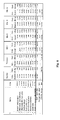
- the table presented in the Fig. 6 shows types of wastes, their calorific value measured at the input to the system and the quantities and calorific value after the process of preparing the wastes to be mineralised. Additionally, it is presented 4 types exemplary mixtures.
- the basic assumption made in order to prepare mixtures is to obtain a batch material for the assumed amount of chemical energy for each of them at the specified range of amount of processed material and within the range of calorific values.
- Fig. 3 presents schematically a longitudinal cross-section of the mineraliser
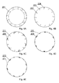
- Fig. 4A-4E present schematically lateral cross-sections of mineraliser along the lines, respectively: A-A, B-B, C-C, D-D, E-E from Fig. 3
- Fig. 4F presents schematically lateral cross-sections of the individual vanes
- Fig. 5 presents schematically the mineraliser in an oblique view, with a considerable inclination.
- the mineraliser has the construction of adjustable configuration that is adjustable accordingly to the moisture content and net calorific value of the mixture supplied from a mixer to a given mineraliser.
- the mineraliser is a steel tube 200, made of high temperature resistant metal sheet and is tilted to the ground at an angle of approx. 1°.
- the mineraliser lies on two raceways and is rotated around its longitudinal symmetry axis through a gear driven by a motor.
- the rotation of tube causes the movement of batch material on vanes 201-211, looking up in the lateral cross-section of the tube, and its falling from a height related with a shape of given vane.
- the inclination of the tube makes the batch material moving slowly along the tube axis.
- the time of passing of the batch material through entire tube, diameter of approx. 2 meters and length of approx. 20 metres is about 30 to 60 minutes, according to adjusted operational parameters of the mineraliser.
- the rotational speed is from approx. 0.5 rpm to approx. 2 rpm.
- the mineraliser is heated as follows: after the ignition of gas burners fuelled with e.g. natural gas or diesel fuel, the heating of tube takes place up to its set temperature, i.e. to approx. 600 °C, and then the gas burners are switched off, and the process is self-sustained.
- gas burners fuelled with e.g. natural gas or diesel fuel the heating of tube takes place up to its set temperature, i.e. to approx. 600 °C, and then the gas burners are switched off, and the process is self-sustained.
- the batch material is fed into the mineraliser through s screw conveyor and the inert waste is received at the end of mineraliser and cooled to a temperature that allows for further transport.
- the rotational speed of mineraliser can be regulated in two ways: (i) with the use of inverters, and (ii) by means of an appropriate adjustment of driving gears.
- an evaporation zone 220 where the evaporation of moisture content takes place
- a mineralisation zone 230 where the appropriate process of gasification and the conversion of waste into the gas and inorganic waste occurs
- a final zone 240 in which there is no more waste but the gas only, where the reception of non-mineralised waste occurs.
- the vanes 201 In the first part of the evaporation zone 220, presented in the cross section of Fig. 4A , the vanes 201 have a shape of flat sheets intended for the initial mixing the batch material.
- vanes 211 are arranged in parallel to the longitudinal symmetry of tube 200, so the angle of inclination with reference to the level is equal to the inclination level of tube 200. These vanes constitute both the means to move the batch material inside the tube and the structure stiffening of the tube 200. Vanes 205-210 have the adjustable inclination angle along the longitudinal symmetry axis of tube 200, preferably within the range of - 1% to +7.5%. The adjustment of inclination angle for vanes 205-210 to a negative value will slow down the movement of batch material along the tube.
- the adjustment of inclination angle of vanes 205-210 contrary to the direction of inclination of the tube results that the material on vanes 205-210 is not moved towards the outlet of the tube and is moved only on vanes 211.
- the adjustment of inclination angle of vanes 205-210 to zero induces that the material on vanes 211 and 205-210 is moved with the same speed.
- the adjustment of inclination angle of vanes 205-210 to a positive angle results that the material on vanes 205-210 is moved faster than the material on vanes 211.
- the adjustment of inclination angle of vanes 205-210 enables to adjust the speed transporting the batch material along mineralization zone 230.
- Vanes 205-210 in mineralization zone have a shape of vessels, the depth of which decreases towards the outlet of tube 200 due to a decreasing amount of material which remains to be mineralised in the direction towards outlet of tube 200.
- vanes 201 arranged as the vanes 201 in the first part of evaporation zone 220, which play a role of limiters for possible residues of non-mineralised material.
- the process of mineralisation in the presented mineraliser can be controlled by changing rotational speed of tube 200 and by the change of inclination angle of vane 205-210.
- rotational speed of tube 200 By changing rotational speed of tube 200, the intensity of pouring the material in cross section of the tube is modified.
- Increasing the rotational speed of mineraliser allows for a faster evaporation of the batch material in zone 220, thus the greater rotational speed should be adjusted for the materials with lower moisture content.
- Change the angle of inclination for vanes 205-210 induces change the speed of moving the material through the mineralization zone 230.
- Increasing the angle of inclination for vanes 205-210 allows for faster passage of the batch material through zone 230, and therefore this adjustment should be applied for materials with a higher calorific value, that are mineralised faster.
- each of mineralisers: 139, 140, 141 may have adjusted other angle of inclination for vanes 205-210 of the mineralization zone. Then, by using suitable mixers 136, 137, 138, each mineraliser has adapted such a combination of the batch material that is processed in its optimal way. For example, if mineraliser 139 has the inclination angle of vanes less than the vane angle adjusted for mineraliser 140, as the batch material for mineraliser 139 should be chosen Mixture II in Fig. 6 , and as the batch material for mineraliser 140 should be chosen Mixture IV in Fig. 6 . For each of the mixtures fed to mineralisers their mean moisture content is calculated on the basis of the data from analysers: 114, 118, 122, 127, 129 and 131 and taking into account the moisture content, the rotational speed of the tube is adjusted.
- In mineralisers 139, 140, 141 follows the process of converting the waste mixture into the high energy reaction gas that is then supplied to the high temperature filters 142 and a catalytic-oxidising afterburner 143, and a secondary afterburner 144, where it is subject to full oxidation to H 2 O and CO 2 in the multi-catalytic system, with large quantities of the reaction heat release, the part of which is returned to sustain the process, and mainly to evaporate water from wastes.
- a hazardous liquid waste 106 can be supplied onto the bed of oxidising catalyst, which increases the energy value of the process of waste disposal.
- the reaction of reduction of nitrogen oxides to N 2 is carried out, if any existed in the processed waste. Then gas is supplied to the heat exchanger 146, where the heat is passed from the gas to the liquid water.
- An alkaline scrubber 148 is activated, when the processed wastes contain halogens or sulphur compounds and is used for their absorption from the purified gas. Gas after the alkaline scrubber is addressed to the heat exchanger 149, in which the gas returns heat to water passed through the heat exchanger, which may be disposed to e.g. municipal heating system or to the dryer 112 or 120 shown in Fig. 1 .
- the cooled gas is directed through the adsorber 150 to the atmosphere, already as practically pure inert gas for the environment, and its purity is to be monitored by using a monitoring system 151.
- a monitoring system 151 may be used for the individual mineralisers or for groups of mineralisers processing wastes of a similar type.
- the gas after purification process is directed to the heat exchanger 146, where the process of exchange of heat between the gas from the process of mineralisation and the air or water supplied to the heat exchanger, the hot, high pressure air or hot and high pressure water steam is formed that are directed to an electricity and heat generating unit 147, in which electricity and heat are produced.
- an adequate number of turbines 147 can be built in to ensure electric power supply resulting from the calorific value of processed wastes and the composition of generated gas.
Landscapes
- Engineering & Computer Science (AREA)
- Mechanical Engineering (AREA)
- General Engineering & Computer Science (AREA)
- Processing Of Solid Wastes (AREA)
- Manufacture And Refinement Of Metals (AREA)
Applications Claiming Priority (1)
| Application Number | Priority Date | Filing Date | Title |
|---|---|---|---|
| PL400076A PL231570B1 (pl) | 2012-07-21 | 2012-07-21 | Sposób produkcji energii elektrycznej i ciepła w procesie termicznego przekształcania różnych rodzajów odpadów w zintegrowanej instalacji oraz zintegrowana instalacja do produkcji energii elektrycznej |
Publications (4)
| Publication Number | Publication Date |
|---|---|
| EP2687782A2 true EP2687782A2 (de) | 2014-01-22 |
| EP2687782A8 EP2687782A8 (de) | 2014-03-12 |
| EP2687782A3 EP2687782A3 (de) | 2015-10-07 |
| EP2687782B1 EP2687782B1 (de) | 2017-05-10 |
Family
ID=46880605
Family Applications (1)
| Application Number | Title | Priority Date | Filing Date |
|---|---|---|---|
| EP12183661.3A Active EP2687782B1 (de) | 2012-07-21 | 2012-09-10 | Verfahren zur Erzeugung von Elektrizität und Wärme in einem Verfahren für Wärmeumwandlung aus verschiedenen Abfällen in einer integrierten Anlage und integrierte Anlage zur Erzeugung von Elektrizität |
Country Status (2)
| Country | Link |
|---|---|
| EP (1) | EP2687782B1 (de) |
| PL (1) | PL231570B1 (de) |
Citations (1)
| Publication number | Priority date | Publication date | Assignee | Title |
|---|---|---|---|---|
| PL364331A1 (en) | 2004-01-08 | 2005-07-11 | Wysocki Michał | A system for mineralization of organic materials used in the power industry, organic, municipal, and industrial wastes as well as mineralization of sludge |
Family Cites Families (4)
| Publication number | Priority date | Publication date | Assignee | Title |
|---|---|---|---|---|
| FR2649187A1 (fr) * | 1989-06-28 | 1991-01-04 | Graffeo Alphonse | Appareil et procede industriel pour l'incineration de boues grasses de laminoirs et de terres polluees |
| FI114116B (fi) * | 2002-06-03 | 2004-08-13 | Metso Automation Oy | Menetelmä ja laitteisto voimakattilan yhteydessä |
| US20080163803A1 (en) * | 2006-12-22 | 2008-07-10 | Covanta Energy Corporation | Method and systems to control municipal solid waste density and higher heating value for improved waste-to-energy boiler operation |
| IT1406771B1 (it) * | 2010-12-23 | 2014-03-07 | Sea Marconi Technologies Di Vander Tumiatti S A S | Impianto modulare per la conduzione di procedimenti di conversione di matrici carboniose |
-
2012
- 2012-07-21 PL PL400076A patent/PL231570B1/pl unknown
- 2012-09-10 EP EP12183661.3A patent/EP2687782B1/de active Active
Patent Citations (1)
| Publication number | Priority date | Publication date | Assignee | Title |
|---|---|---|---|---|
| PL364331A1 (en) | 2004-01-08 | 2005-07-11 | Wysocki Michał | A system for mineralization of organic materials used in the power industry, organic, municipal, and industrial wastes as well as mineralization of sludge |
Non-Patent Citations (1)
| Title |
|---|
| POLISH JOURNAL OF LAWS, no. 112, 2001 |
Also Published As
| Publication number | Publication date |
|---|---|
| EP2687782B1 (de) | 2017-05-10 |
| PL231570B1 (pl) | 2019-03-29 |
| EP2687782A8 (de) | 2014-03-12 |
| PL400076A1 (pl) | 2014-02-03 |
| EP2687782A3 (de) | 2015-10-07 |
Similar Documents
| Publication | Publication Date | Title |
|---|---|---|
| Zhang et al. | Status and development of sludge incineration in China | |
| Kijo-Kleczkowska et al. | Experimental research of sewage sludge with coal and biomass co-combustion, in pellet form | |
| AU2007243632B2 (en) | Method and plant for processing waste | |
| US7189074B2 (en) | Method and process for co-combustion in a waste to-energy facility | |
| EP2860450B1 (de) | Verfahren zur thermischen behandlung von organischen abfallstoffen | |
| CN104058615B (zh) | 一种水泥窑协同处置生活垃圾的系统 | |
| CN203791331U (zh) | 一种水泥窑协同处理城市生活垃圾的系统 | |
| Fang et al. | Using sewage sludge as a denitration agent and secondary fuel in a cement plant: A case study | |
| CN103934254B (zh) | 一种水泥窑协同处理城市生活垃圾的系统及方法 | |
| CN107417061B (zh) | 污泥的处理方法及处理系统 | |
| CN110513693B (zh) | 一种污泥焚烧方法 | |
| CN201748434U (zh) | 垃圾焚烧处理装置 | |
| RU2663312C1 (ru) | Устройство для термической утилизации углеводородсодержащих отходов, оснащенное вихревой камерой сгорания с внутренним пиролизным реактором, и способ его работы | |
| CN1186559C (zh) | 回转炉床垃圾气化焚烧处理方法 | |
| CN201272768Y (zh) | 不用常规燃料助燃的生活垃圾转化系统及设备 | |
| CN105945028B (zh) | 生活垃圾焚烧再生利用工艺 | |
| EP2687782B1 (de) | Verfahren zur Erzeugung von Elektrizität und Wärme in einem Verfahren für Wärmeumwandlung aus verschiedenen Abfällen in einer integrierten Anlage und integrierte Anlage zur Erzeugung von Elektrizität | |
| JP7628577B2 (ja) | 二酸化炭素吸収剤、二酸化炭素吸収設備、二酸化炭素吸収方法及び二酸化炭素吸収剤の製造方法 | |
| RU2570331C1 (ru) | Способ переработки твердых бытовых и промышленных отходов и установка для его реализации | |
| JP3707754B2 (ja) | 廃棄物処理システムと方法及びそれにより製造されたセメント | |
| CN217763445U (zh) | 一种工业固废及污泥处置系统 | |
| RU2502017C1 (ru) | Способ экологически чистой переработки твердых бытовых отходов с производством тепловой энергии и строительных материалов и мусоросжигательный завод для его осуществления | |
| Xie et al. | A burning experiment study of an integral medical waste incinerator | |
| PL231914B1 (pl) | Sposób termicznego przekształcania odpadów organicznych oraz układ do termicznego przekształcania odpadów organicznych | |
| RU2502018C1 (ru) | Комплексная районная тепловая станция для экологически чистой переработки твердых бытовых отходов с производством тепловой энергии и строительных материалов |
Legal Events
| Date | Code | Title | Description |
|---|---|---|---|
| PUAI | Public reference made under article 153(3) epc to a published international application that has entered the european phase |
Free format text: ORIGINAL CODE: 0009012 |
|
| AK | Designated contracting states |
Kind code of ref document: A2 Designated state(s): AL AT BE BG CH CY CZ DE DK EE ES FI FR GB GR HR HU IE IS IT LI LT LU LV MC MK MT NL NO PL PT RO RS SE SI SK SM TR |
|
| AX | Request for extension of the european patent |
Extension state: BA ME |
|
| RIN1 | Information on inventor provided before grant (corrected) |
Inventor name: WYSOCKI, ZYGMUNT Inventor name: WYSOCKI, MICHAL Inventor name: BAK, TADEUSZ |
|
| PUAL | Search report despatched |
Free format text: ORIGINAL CODE: 0009013 |
|
| AK | Designated contracting states |
Kind code of ref document: A3 Designated state(s): AL AT BE BG CH CY CZ DE DK EE ES FI FR GB GR HR HU IE IS IT LI LT LU LV MC MK MT NL NO PL PT RO RS SE SI SK SM TR |
|
| AX | Request for extension of the european patent |
Extension state: BA ME |
|
| RIC1 | Information provided on ipc code assigned before grant |
Ipc: F23G 5/20 20060101AFI20150902BHEP Ipc: F23G 5/00 20060101ALI20150902BHEP |
|
| 17P | Request for examination filed |
Effective date: 20160519 |
|
| RBV | Designated contracting states (corrected) |
Designated state(s): AL AT BE BG CH CY CZ DE DK EE ES FI FR GB GR HR HU IE IS IT LI LT LU LV MC MK MT NL NO PL PT RO RS SE SI SK SM TR |
|
| GRAP | Despatch of communication of intention to grant a patent |
Free format text: ORIGINAL CODE: EPIDOSNIGR1 |
|
| INTG | Intention to grant announced |
Effective date: 20161007 |
|
| STAA | Information on the status of an ep patent application or granted ep patent |
Free format text: STATUS: GRANT OF PATENT IS INTENDED |
|
| GRAS | Grant fee paid |
Free format text: ORIGINAL CODE: EPIDOSNIGR3 |
|
| GRAA | (expected) grant |
Free format text: ORIGINAL CODE: 0009210 |
|
| STAA | Information on the status of an ep patent application or granted ep patent |
Free format text: STATUS: THE PATENT HAS BEEN GRANTED |
|
| AK | Designated contracting states |
Kind code of ref document: B1 Designated state(s): AL AT BE BG CH CY CZ DE DK EE ES FI FR GB GR HR HU IE IS IT LI LT LU LV MC MK MT NL NO PL PT RO RS SE SI SK SM TR |
|
| REG | Reference to a national code |
Ref country code: GB Ref legal event code: FG4D |
|
| REG | Reference to a national code |
Ref country code: AT Ref legal event code: REF Ref document number: 892757 Country of ref document: AT Kind code of ref document: T Effective date: 20170515 Ref country code: CH Ref legal event code: EP |
|
| REG | Reference to a national code |
Ref country code: IE Ref legal event code: FG4D |
|
| REG | Reference to a national code |
Ref country code: DE Ref legal event code: R096 Ref document number: 602012032180 Country of ref document: DE |
|
| REG | Reference to a national code |
Ref country code: NL Ref legal event code: MP Effective date: 20170510 |
|
| REG | Reference to a national code |
Ref country code: LT Ref legal event code: MG4D |
|
| REG | Reference to a national code |
Ref country code: AT Ref legal event code: MK05 Ref document number: 892757 Country of ref document: AT Kind code of ref document: T Effective date: 20170510 |
|
| PG25 | Lapsed in a contracting state [announced via postgrant information from national office to epo] |
Ref country code: NO Free format text: LAPSE BECAUSE OF FAILURE TO SUBMIT A TRANSLATION OF THE DESCRIPTION OR TO PAY THE FEE WITHIN THE PRESCRIBED TIME-LIMIT Effective date: 20170810 Ref country code: GR Free format text: LAPSE BECAUSE OF FAILURE TO SUBMIT A TRANSLATION OF THE DESCRIPTION OR TO PAY THE FEE WITHIN THE PRESCRIBED TIME-LIMIT Effective date: 20170811 Ref country code: FI Free format text: LAPSE BECAUSE OF FAILURE TO SUBMIT A TRANSLATION OF THE DESCRIPTION OR TO PAY THE FEE WITHIN THE PRESCRIBED TIME-LIMIT Effective date: 20170510 Ref country code: HR Free format text: LAPSE BECAUSE OF FAILURE TO SUBMIT A TRANSLATION OF THE DESCRIPTION OR TO PAY THE FEE WITHIN THE PRESCRIBED TIME-LIMIT Effective date: 20170510 Ref country code: AT Free format text: LAPSE BECAUSE OF FAILURE TO SUBMIT A TRANSLATION OF THE DESCRIPTION OR TO PAY THE FEE WITHIN THE PRESCRIBED TIME-LIMIT Effective date: 20170510 Ref country code: ES Free format text: LAPSE BECAUSE OF FAILURE TO SUBMIT A TRANSLATION OF THE DESCRIPTION OR TO PAY THE FEE WITHIN THE PRESCRIBED TIME-LIMIT Effective date: 20170510 Ref country code: LT Free format text: LAPSE BECAUSE OF FAILURE TO SUBMIT A TRANSLATION OF THE DESCRIPTION OR TO PAY THE FEE WITHIN THE PRESCRIBED TIME-LIMIT Effective date: 20170510 |
|
| PG25 | Lapsed in a contracting state [announced via postgrant information from national office to epo] |
Ref country code: LV Free format text: LAPSE BECAUSE OF FAILURE TO SUBMIT A TRANSLATION OF THE DESCRIPTION OR TO PAY THE FEE WITHIN THE PRESCRIBED TIME-LIMIT Effective date: 20170510 Ref country code: SE Free format text: LAPSE BECAUSE OF FAILURE TO SUBMIT A TRANSLATION OF THE DESCRIPTION OR TO PAY THE FEE WITHIN THE PRESCRIBED TIME-LIMIT Effective date: 20170510 Ref country code: NL Free format text: LAPSE BECAUSE OF FAILURE TO SUBMIT A TRANSLATION OF THE DESCRIPTION OR TO PAY THE FEE WITHIN THE PRESCRIBED TIME-LIMIT Effective date: 20170510 Ref country code: BG Free format text: LAPSE BECAUSE OF FAILURE TO SUBMIT A TRANSLATION OF THE DESCRIPTION OR TO PAY THE FEE WITHIN THE PRESCRIBED TIME-LIMIT Effective date: 20170810 Ref country code: RS Free format text: LAPSE BECAUSE OF FAILURE TO SUBMIT A TRANSLATION OF THE DESCRIPTION OR TO PAY THE FEE WITHIN THE PRESCRIBED TIME-LIMIT Effective date: 20170510 Ref country code: PL Free format text: LAPSE BECAUSE OF FAILURE TO SUBMIT A TRANSLATION OF THE DESCRIPTION OR TO PAY THE FEE WITHIN THE PRESCRIBED TIME-LIMIT Effective date: 20170510 Ref country code: IS Free format text: LAPSE BECAUSE OF FAILURE TO SUBMIT A TRANSLATION OF THE DESCRIPTION OR TO PAY THE FEE WITHIN THE PRESCRIBED TIME-LIMIT Effective date: 20170910 |
|
| PG25 | Lapsed in a contracting state [announced via postgrant information from national office to epo] |
Ref country code: EE Free format text: LAPSE BECAUSE OF FAILURE TO SUBMIT A TRANSLATION OF THE DESCRIPTION OR TO PAY THE FEE WITHIN THE PRESCRIBED TIME-LIMIT Effective date: 20170510 Ref country code: SK Free format text: LAPSE BECAUSE OF FAILURE TO SUBMIT A TRANSLATION OF THE DESCRIPTION OR TO PAY THE FEE WITHIN THE PRESCRIBED TIME-LIMIT Effective date: 20170510 Ref country code: RO Free format text: LAPSE BECAUSE OF FAILURE TO SUBMIT A TRANSLATION OF THE DESCRIPTION OR TO PAY THE FEE WITHIN THE PRESCRIBED TIME-LIMIT Effective date: 20170510 Ref country code: CZ Free format text: LAPSE BECAUSE OF FAILURE TO SUBMIT A TRANSLATION OF THE DESCRIPTION OR TO PAY THE FEE WITHIN THE PRESCRIBED TIME-LIMIT Effective date: 20170510 Ref country code: DK Free format text: LAPSE BECAUSE OF FAILURE TO SUBMIT A TRANSLATION OF THE DESCRIPTION OR TO PAY THE FEE WITHIN THE PRESCRIBED TIME-LIMIT Effective date: 20170510 |
|
| REG | Reference to a national code |
Ref country code: DE Ref legal event code: R097 Ref document number: 602012032180 Country of ref document: DE |
|
| PG25 | Lapsed in a contracting state [announced via postgrant information from national office to epo] |
Ref country code: SM Free format text: LAPSE BECAUSE OF FAILURE TO SUBMIT A TRANSLATION OF THE DESCRIPTION OR TO PAY THE FEE WITHIN THE PRESCRIBED TIME-LIMIT Effective date: 20170510 Ref country code: IT Free format text: LAPSE BECAUSE OF FAILURE TO SUBMIT A TRANSLATION OF THE DESCRIPTION OR TO PAY THE FEE WITHIN THE PRESCRIBED TIME-LIMIT Effective date: 20170510 |
|
| PLBE | No opposition filed within time limit |
Free format text: ORIGINAL CODE: 0009261 |
|
| STAA | Information on the status of an ep patent application or granted ep patent |
Free format text: STATUS: NO OPPOSITION FILED WITHIN TIME LIMIT |
|
| 26N | No opposition filed |
Effective date: 20180213 |
|
| PGFP | Annual fee paid to national office [announced via postgrant information from national office to epo] |
Ref country code: GB Payment date: 20180326 Year of fee payment: 6 |
|
| REG | Reference to a national code |
Ref country code: CH Ref legal event code: PL |
|
| PG25 | Lapsed in a contracting state [announced via postgrant information from national office to epo] |
Ref country code: SI Free format text: LAPSE BECAUSE OF FAILURE TO SUBMIT A TRANSLATION OF THE DESCRIPTION OR TO PAY THE FEE WITHIN THE PRESCRIBED TIME-LIMIT Effective date: 20170510 Ref country code: MC Free format text: LAPSE BECAUSE OF FAILURE TO SUBMIT A TRANSLATION OF THE DESCRIPTION OR TO PAY THE FEE WITHIN THE PRESCRIBED TIME-LIMIT Effective date: 20170510 |
|
| REG | Reference to a national code |
Ref country code: IE Ref legal event code: MM4A |
|
| REG | Reference to a national code |
Ref country code: BE Ref legal event code: MM Effective date: 20170930 |
|
| PG25 | Lapsed in a contracting state [announced via postgrant information from national office to epo] |
Ref country code: LU Free format text: LAPSE BECAUSE OF NON-PAYMENT OF DUE FEES Effective date: 20170910 |
|
| REG | Reference to a national code |
Ref country code: FR Ref legal event code: ST Effective date: 20180531 |
|
| PG25 | Lapsed in a contracting state [announced via postgrant information from national office to epo] |
Ref country code: CH Free format text: LAPSE BECAUSE OF NON-PAYMENT OF DUE FEES Effective date: 20170930 Ref country code: LI Free format text: LAPSE BECAUSE OF NON-PAYMENT OF DUE FEES Effective date: 20170930 Ref country code: IE Free format text: LAPSE BECAUSE OF NON-PAYMENT OF DUE FEES Effective date: 20170910 |
|
| PG25 | Lapsed in a contracting state [announced via postgrant information from national office to epo] |
Ref country code: FR Free format text: LAPSE BECAUSE OF NON-PAYMENT OF DUE FEES Effective date: 20171002 Ref country code: BE Free format text: LAPSE BECAUSE OF NON-PAYMENT OF DUE FEES Effective date: 20170930 |
|
| PG25 | Lapsed in a contracting state [announced via postgrant information from national office to epo] |
Ref country code: MT Free format text: LAPSE BECAUSE OF NON-PAYMENT OF DUE FEES Effective date: 20170910 |
|
| GBPC | Gb: european patent ceased through non-payment of renewal fee |
Effective date: 20180910 |
|
| PG25 | Lapsed in a contracting state [announced via postgrant information from national office to epo] |
Ref country code: HU Free format text: LAPSE BECAUSE OF FAILURE TO SUBMIT A TRANSLATION OF THE DESCRIPTION OR TO PAY THE FEE WITHIN THE PRESCRIBED TIME-LIMIT; INVALID AB INITIO Effective date: 20120910 |
|
| PG25 | Lapsed in a contracting state [announced via postgrant information from national office to epo] |
Ref country code: GB Free format text: LAPSE BECAUSE OF NON-PAYMENT OF DUE FEES Effective date: 20180910 Ref country code: CY Free format text: LAPSE BECAUSE OF NON-PAYMENT OF DUE FEES Effective date: 20170510 |
|
| PG25 | Lapsed in a contracting state [announced via postgrant information from national office to epo] |
Ref country code: MK Free format text: LAPSE BECAUSE OF FAILURE TO SUBMIT A TRANSLATION OF THE DESCRIPTION OR TO PAY THE FEE WITHIN THE PRESCRIBED TIME-LIMIT Effective date: 20170510 |
|
| PG25 | Lapsed in a contracting state [announced via postgrant information from national office to epo] |
Ref country code: TR Free format text: LAPSE BECAUSE OF FAILURE TO SUBMIT A TRANSLATION OF THE DESCRIPTION OR TO PAY THE FEE WITHIN THE PRESCRIBED TIME-LIMIT Effective date: 20170510 |
|
| PG25 | Lapsed in a contracting state [announced via postgrant information from national office to epo] |
Ref country code: PT Free format text: LAPSE BECAUSE OF FAILURE TO SUBMIT A TRANSLATION OF THE DESCRIPTION OR TO PAY THE FEE WITHIN THE PRESCRIBED TIME-LIMIT Effective date: 20170510 |
|
| PG25 | Lapsed in a contracting state [announced via postgrant information from national office to epo] |
Ref country code: AL Free format text: LAPSE BECAUSE OF FAILURE TO SUBMIT A TRANSLATION OF THE DESCRIPTION OR TO PAY THE FEE WITHIN THE PRESCRIBED TIME-LIMIT Effective date: 20170510 |
|
| REG | Reference to a national code |
Ref country code: DE Ref legal event code: R082 Ref document number: 602012032180 Country of ref document: DE Representative=s name: HEILEIN IP LAW, DE |
|
| PGFP | Annual fee paid to national office [announced via postgrant information from national office to epo] |
Ref country code: DE Payment date: 20260302 Year of fee payment: 14 |