EP2687825A2 - Débitmètre à noyau magnétique - Google Patents
Débitmètre à noyau magnétique Download PDFInfo
- Publication number
- EP2687825A2 EP2687825A2 EP20130003370 EP13003370A EP2687825A2 EP 2687825 A2 EP2687825 A2 EP 2687825A2 EP 20130003370 EP20130003370 EP 20130003370 EP 13003370 A EP13003370 A EP 13003370A EP 2687825 A2 EP2687825 A2 EP 2687825A2
- Authority
- EP
- European Patent Office
- Prior art keywords
- magnetization
- magnetic field
- medium
- segment
- nuclear magnetic
- Prior art date
- Legal status (The legal status is an assumption and is not a legal conclusion. Google has not performed a legal analysis and makes no representation as to the accuracy of the status listed.)
- Granted
Links
Images


Classifications
-
- G—PHYSICS
- G01—MEASURING; TESTING
- G01F—MEASURING VOLUME, VOLUME FLOW, MASS FLOW OR LIQUID LEVEL; METERING BY VOLUME
- G01F1/00—Measuring the volume flow or mass flow of fluid or fluent solid material wherein the fluid passes through a meter in a continuous flow
- G01F1/704—Measuring the volume flow or mass flow of fluid or fluent solid material wherein the fluid passes through a meter in a continuous flow using marked regions or existing inhomogeneities within the fluid stream, e.g. statistically occurring variations in a fluid parameter
- G01F1/708—Measuring the time taken to traverse a fixed distance
- G01F1/716—Measuring the time taken to traverse a fixed distance using electron paramagnetic resonance [EPR] or nuclear magnetic resonance [NMR]
-
- G—PHYSICS
- G01—MEASURING; TESTING
- G01F—MEASURING VOLUME, VOLUME FLOW, MASS FLOW OR LIQUID LEVEL; METERING BY VOLUME
- G01F1/00—Measuring the volume flow or mass flow of fluid or fluent solid material wherein the fluid passes through a meter in a continuous flow
- G01F1/56—Measuring the volume flow or mass flow of fluid or fluent solid material wherein the fluid passes through a meter in a continuous flow by using electric or magnetic effects
Definitions
- the invention relates to a nuclear magnetic flowmeter for flow measurement of a medium flowing through a measuring tube with a magnetizing device for magnetizing the flowing through the measuring tube medium over a magnetization along the longitudinal axis of the measuring tube, wherein the magnetizing means is provided for generating the magnetization of the medium serving magnetic field with permanent magnets and at least two magnetization segments arranged one after the other in the direction of the longitudinal axis of the measuring tube.
- the atomic nuclei of elements possessing a nuclear spin also possess a magnetic moment caused by the nuclear spin.
- the nuclear spin can be thought of as an angular momentum writable by a vector and, correspondingly, the magnetic moment can also be described by a vector that is parallel to the vector of the angular momentum.
- the vector of the magnetic moment of an atomic nucleus aligns in the presence of a macroscopic magnetic field parallel to the vector of the macroscopic magnetic field at the location of the atomic nucleus.
- the vector of the magnetic moment of the atomic nucleus precesses around the vector of the macroscopic magnetic field at the point of the atomic nucleus.
- the frequency of the precession is called the Larmor frequency ⁇ L and is proportional to the magnitude of the magnetic field strength B.
- Nuclear magnetic resonance measurement or analysis techniques Measurement and analysis techniques that exploit the property of precession of atomic nuclei with a magnetic moment in the presence of a macroscopic magnetic field are referred to as nuclear magnetic resonance measurement or analysis techniques.
- the term for nuclear magnetic resonance is nuclear magnetic resonance.
- the voltages induced by the precessing atomic nuclei under different boundary conditions in a sensor coil are used as output variables for the measurement and analysis methods.
- An example of measuring devices that exploit the nuclear magnetic resonance the nuclear magnetic Flowmeters that measure the flow of the multiphase medium flowing through the measuring tube and analyze the medium.
- the prerequisite for an analysis using nuclear magnetic resonance is that the phases of the medium to be analyzed can be excited into distinguishable nuclear magnetic resonances.
- the analysis may include the flow rates of the individual phases of the medium and the relative proportions of the individual phases on the multiphase medium.
- Nuclear magnetic flowmeters may e.g. B. are used for the analysis of funded from oil wells multiphase medium.
- the medium consists essentially of the phases crude oil, natural gas and salt water, all phases containing hydrogen nuclei.
- test separators The analysis of the pumped from oil sources medium can also be done with so-called test separators. These divert a small portion of the pumped medium, separate the individual phases of the medium from each other and determine the proportions of the individual phases of the medium.
- test separators are unable to reliably measure crude oil levels less than 5%. Since the crude oil content of each source steadily decreases and the crude oil content of a variety of sources is already less than 5%, it is currently not possible to economically exploit these sources using test separators. In order to continue to exploit sources with a very low crude oil content, correspondingly accurate flowmeters are required.
- the Larmor frequency ⁇ L is proportional to the magnitude of the magnetic field strength B of the macroscopic magnetic field in the medium to be examined and thus the amount of magnetic field strength also acts directly on the frequency of the voltage induced in the sensor coil .
- the direction of the macroscopic magnetic field with respect to the orientation of the sensor coil also influences the voltages induced in the sensor coil. In general, deviations of the macroscopic magnetic field passing through the medium from the ideal of the homogeneous magnetic field lead to a reduced measurement quality and thus to inaccurate measurement results.
- the nuclear magnetic flowmeter is known, from which the invention proceeds.
- the magnetization elements belonging to the magnetization device they are of hollow-cylindrical design and have a homogeneous magnetic field in their interiors.
- the magnetization segments are arranged one behind the other on the measuring tube such that their concentric longitudinal axes coincide with the longitudinal axis of the measuring tube.
- the magnetization of the medium flowing through the measuring tube can thereby be adjusted in different ways, that is to say be varied, so that the homogeneous magnetic fields of the individual magnetizing elements are aligned either parallel or antiparallel to one another.
- Figure 7 of the American patent application 2008 / 0,174,309 shows in detail a magnetization device with six successively arranged magnetization segments.
- all magnetization segments are adjusted so that the homogeneous magnetic fields of the individual magnetization segments in the medium are aligned parallel to each other.
- three magnetization segments are combined to form a group in the realization according to the sketch b).
- the homogeneous magnetic fields of the magnetization segments are aligned parallel to each other.
- the homogeneous magnetic fields of one group are aligned antiparallel to the homogeneous magnetic fields of the other group.
- the object of the invention is to specify a nuclear magnetic flowmeter improved with regard to the achievable quality of the measurement results.
- the nuclear magnetic flowmeter according to the invention is initially and essentially characterized in that the magnetic field also has the same direction over the length of the magnetization path of different magnetic field strength in the medium over the entire magnetization path or all magnetic fields have the same direction.
- a nuclear magnetic flowmeter constructed in accordance with the invention determines the flow rates of the individual phases of the medium and the relative proportions of individual phases on a multiphase medium in the measuring tube more accurately than a nuclear magnetic flowmeter not according to the invention, for example is as previously described in detail.
- nuclear magnetic flowmeter in the context of the invention is primarily a nuclear magnetic flowmeter, but that what the nuclear magnetic flowmeter according to the invention features according to the invention is not limited to the application of nuclear magnetic flowmeters, but also can be used elsewhere, for Example in general in the petrochemical industry or in the chemical industry.
- the magnetic field has the same direction in the medium over the entire magnetization path or all magnetic fields have the same direction, this does not mean that this same direction can only be a very specific one. Rather, the magnetic field or all magnetic fields can have any direction, with the restriction that they all have the same direction.
- a particularly preferred embodiment of the nuclear magnetic flowmeter according to the invention is additionally characterized in that each of the magnetization segments has an inner carrier equipped with permanent magnets and an outer carrier equipped with permanent magnets and the inner carrier is arranged around the measuring tube and the outer carrier around the inner carrier and that for varying the magnetic field strength in Medium and thus also for the variation of the magnetization of the medium, the orientation between the inner support and the outer support by rotation of the inner support and / or the outer support is adjustable about a segment rotation axis, wherein usually the segment axis of rotation coincides with the longitudinal axis of the measuring tube.
- the magnetic field strength in the medium which is caused by superposition of the magnetic field generated by the permanent magnet of the inner support and the magnetic field generated by the permanent magnet of the outer support results, adjustable.
- the magnetization of the medium flowing through the measuring tube can also be set.
- An adjustment option is characterized in that the magnetic fields of the inner support and the outer support "add up", the resulting magnetic field thus has a magnetic field strength which is twice as large as the magnetic field strength realized by the inner support or the magnetic field strength realized by the outer support.
- the magnetic fields cancel each other, so that no magnetic field is effective in the medium.
- the orientation between the inner support and the outer support can be realized that both the inner support and the outer support is rotated about the segment axis of rotation.
- the inner support is realized fixed in relation to the measuring tube and the outer support, arranged concentrically around the inner support, is rotatable about the segment rotation axis.
- the rotatable realization of the outer support with respect to the inner support is advantageous over the rotatable arrangement of the inner support with respect to the outer support, because the inner support is covered by the outer support and therefore the operation of the outer support is easier to implement than the operation of the inner support.
- the rotatable about the segment axis of rotation storage of the outer support can be implemented by the fact that the inner support is connected at each of its two ends with respect to the segment axis of rotation with one segment carrier and the outer carrier with the segment carriers at least forms a thrust bearing, while the outer carrier with the inner carrier forms at least one radial slide bearing.
- the freedom of movement of the outer carrier remaining through the axial sliding bearing and the radial sliding bearing is the rotatability of the outer carrier about the segment rotational axis.
- the actuation of the rotatably mounted outer carrier can be effected by an actuator.
- the actuator may comprise a sprocket arranged concentrically to the segment rotational axis on the outer carrier, a pinion engaging in the sprocket and an electric motor rotating the pinion.
- the electric motor By driving the electric motor, the torque applied by the electric motor is transmitted via the pinion to the ring gear, so that the outer support is rotated with respect to the inner support.
- electric motors can be used synchronous motor and, preferably stepper motors.
- the actuator can also be designed to set the orientation with the maximum rotating field in the medium and the minimum magnetic field in the medium.
- the orientation with the maximum magnetic field in the medium and with the minimum magnetic field in the medium is known by the number of steps in a given direction of rotation, starting from a known initial orientation.
- the initial orientation may be detectable by a flag on the outer support and a non-co-rotating light barrier.
- the orientation with the maximum magnetic field in the medium and with the minimum magnetic field in the medium can be signaled by flags and light barriers.
- the use of a stepping motor is not required and, for example, a synchronous motor may be used.
- other orientations between the inner support and the outer support can be reproducibly adjusted by the means described above.
- the medium is magnetized by a magnetization segment of a second type equipped with permanent magnets, in which the magnetic resistance for varying the magnetic field strength in the medium and thus also for varying the magnetization of the medium is adjustable.
- the adjustability of the magnetic resistance can be implemented, for example, in that the magnetization segment consists of a first sub-segment and of a second sub-segment and are spaced apart by the sub-segments.
- the gap resulting in spacing between the first sub-segment and the second sub-segment represents the magnetic resistance of the magnetization segment and is adjustable over the size of the gap.
- the magnetic resistance can also be influenced in this yoke.
- this yoke there may be a slot through which the magnetic flux flows, and by inserting or withdrawing a good magnetic conducting filling into the slot, the magnetic resistance may be adjusted.
- the magnetization device or at least one magnetization segment is arranged movably along the longitudinal axis of the measuring tube. Due to the adjustable distance of the magnetization device or the magnetization segment along the longitudinal axis of the measuring tube to a measuring device, the magnetization of the medium is adjustable on the measuring device. In this way measurements can be made with different magnetizations of the medium.
- both the permanent magnets of the inner support are then arranged as a Halbach array and the permanent magnets of the outer support are arranged as a Halbach array.
- the magnetic field of the inner support extends outside of the inner support substantially into the interior of the inner support.
- the magnetic field of the outer carrier outside the outer carrier extends substantially into the interior of the outer carrier.
- the magnetization of the medium flowing through the measuring tube is effected exclusively by magnetic fields generated by permanent magnets.
- the variation of the magnetic field strength in the medium takes place by rotation of the outer carrier and the inner carrier to each other and optionally by varying the magnetic resistance.
- the variation of the magnetic field strength takes place by mechanical changes to the magnetization device.
- at least one electromagnet is arranged on the magnetization device such that the magnetic field of the electromagnet is aligned parallel or antiparallel to the magnetic field of the magnetization device.
- the electromagnet By means of the electromagnet, it is thus possible to either reduce the magnetic field present in the medium by the magnetic field strength generated by the electromagnet or to increase the magnetic field strength by the magnetic field strength generated by the electromagnet. Mechanical changes to the variation of the magnetic field strength in the medium are therefore no longer necessary.
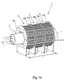
- the invention relates to a nuclear magnetic flowmeter for measuring a medium 6 flowing through a measuring tube 5 with a magnetizing device 1 for magnetizing the medium 6 flowing through the measuring tube 5 over a magnetizing path 7 along the longitudinal axis 8 of the measuring tube 5.
- the magnetizing device 1 is for generating of the magnetization of the medium 6 serving magnetic field 3, 4 provided with permanent magnets 2 and the magnetization device 1 at least two in the direction of the longitudinal axis 8 of the measuring tube 5 successively arranged magnetization segments 9. This is largely not shown in the figures, because the figures essentially show the magnetization device 1 belonging to the nuclear magnetic flowmeter according to the invention.
- the magnetic field 3, 4 in the medium 6 over the entire magnetization 7 on the same direction.
- the figures show an embodiment of a magnetization device 1 belonging to the nuclear magnetic flowmeter according to the invention, wherein in the Fig. 1a the magnetization device 1 is shown in its entirety.
- a plurality of rod-shaped permanent magnets 2, see FIGS. 2a to 5b generates a magnetic field 3, 4, see the Figures 1b and 3 to 5b , which passes through a flowing through a measuring tube 5 medium 6.
- the geomagnetic field is disregarded.
- the enforcement of the medium 6 with the magnetic field 3, 4 via a magnetization path 7, which extends along the Longitudinal axis 8 of the measuring tube 5 extends.
- the measuring tube 5, at least over the magnetization section 7, of a material which does not affect magnetic fields.
- the magnetization of the flowing medium 6 takes place during the residence time of the medium 6 in the region of the magnetization path 7 resulting from the length of the magnetization path 7 and the flow velocity of the medium 6.
- the magnetization device 1 is modularly constructed from individual magnetization segments 9, that is, it can comprise any number of magnetization segments 9.
- the embodiment comprises three magnetization segments 9, see Fig. 1a but could also have fewer or more magnetization segments 9 due to the modularity.
- the three magnetization segments 9 each have the same length Colourmagnet Deutschensumblen, which together form the magnetization 7.
- the magnetic field 3, 4 generated by the permanent magnets 2 in the medium 6 via the magnetization path 7 has only a single direction, see Fig. 1b , If we speak here of a single direction of the magnetic field 3, 4 in the medium 6 over the magnetization path 7, then the variation of the direction does not exclude. However, the variations of the direction are so small that the desired measurement accuracy is achieved. Edge effects of the magnetic field 3, 4, as they occur, for example, at the ends of the magnetization path 7, are not shown in the figures.
- the magnetization segment 9 comprises a basically hollow-cylindrical inner support 10 with the concentric inner longitudinal axis 11 and a basically hollow cylindrical outer support 12 with the concentric outer longitudinal axis 13, wherein the outer support 12 is rotatable about a segment axis of rotation 14.
- the inner support 10 consists essentially of a basically hollow cylindrical inner magnet carrier 15 and two disc-ring-shaped inner rings 16a, 16b, and the inner radius of the inner support 10 about the inner support longitudinal axis 11 is greater than the outer radius of the measuring tube 5.
- a plurality of rod magnetic recordings 17 is provided in the inner magnet carrier 15, a plurality of rod magnetic recordings 17 is provided.
- Each of the bar magnet holders 17 has an axis parallel to the inner longitudinal axis 11 and consists of a plurality of concentric with their respective axis Stabmagnetausappel 18.
- the bar magnet 17 extend over the entire length of the inner magnet carrier 15, and all belonging to a bar magnet holder 17 StabmagnetausEnglishtown 18 have same rectangular inner cross section. When talking about the length of a body, it is meant the extension of the body along its longitudinal axis.
- the rod-shaped permanent magnets 2 are used.
- the permanent magnets 2 are inserted from one or the other end face of the inner magnet carrier 15 into the bar magnet receptacles 17, and the length of the inserted permanent magnet 2 corresponds to the length of the inner magnet carrier 15.
- the inner cross sections of the Stabmagnetaus traditions 18 are adapted to the outer cross sections of the permanent magnet 2 in that the inner magnetic carrier 15 non-rotatably aligns the permanent magnets 2 inserted in the bar magnet holders 17 about their respective longitudinal axis.
- the inner magnet carrier 15 prevents any movements of the permanent magnet 2 used in the direction of the inner longitudinal axis 11, which is why the permanent magnet 2 used are movable in this direction.
- the inner ring 16a is fixedly connected to the one end face, the inner ring 16b to the other end face of the inner magnet carrier 15 by screw connections.
- the inner rings 16a and 16b connected to the inner magnet carrier 15 prevent movements of the permanent magnets 2 used in the direction of the inner longitudinal axis 11.
- the permanent magnets 2 are completely fixed by the matched cross-sectional areas of the permanent magnets 2 and the Stabmagnetaus principle 18 and by the inner rings 16a, 16b ,
- the outwardly directed end face of each of the inner rings 16a, 16b lies in a plane perpendicular to the inner longitudinal axis 11 of the support.
- the outwardly directed concentric surface of the inner ring 16a and the outwardly directed concentric surface of the inner ring 16b lie in a common inner circle cylinder surface, which is not pierced by the inner magnetic carrier 15.
- the inner magnet carrier 15 and connected to this inner rings 16a, 16b are aligned concentrically to the inner longitudinal axis 11 of the carrier.
- the outer support 12 consists essentially of a basically hollow cylindrical outer magnet carrier 19 and two disc-ring-shaped outer rings 20a, 20b.
- a plurality of bar magnet holders 17 are provided in the outer magnetic carrier 19, a plurality of bar magnet holders 17 are provided.
- Each of the bar magnet holders 17 has an axis parallel to the outer carrier longitudinal axis 13 and consists of a plurality of concentric to their respective axis provided Stabmagnetausappel 18.
- the bar magnet receptacles 17 extend over the entire length of the outer magnet carrier 19, and all belonging to a bar magnet holder 17 StabmagnetausEnglishtown 18 have same rectangular inner cross section.
- the rectangular, rod-shaped permanent magnet 2 are used in the bar magnet holders 17, the rectangular, rod-shaped permanent magnet 2 are used.
- the permanent magnets 2 are inserted from one or the other end face of the outer magnet carrier 19 into the bar magnet holders 17 and the length of the permanent magnets 2 used corresponds to the length of the outer magnet carrier 19.
- the inner cross sections of the bar magnet recesses 18 are adapted to the outer cross sections of the permanent magnets, that the outer magnetic carrier 19, the permanent magnet 2 inserted into the rod magnetic recordings 17 against rotation about their respective longitudinal axis aligns.
- the inner magnet carrier 15 prevents any movements of the permanent magnet 2 used in the direction of the outer longitudinal axis 13, which is why the permanent magnet 2 used are movable in this direction.
- the outer ring 20a is firmly connected to the one, the outer ring 20b with the other end face of the outer magnetic carrier 19 by screw.
- the outer rings 20a, 20b connected to the outer magnetic carrier 19 prevent movements of the permanent magnets 2 used in the direction of the outer longitudinal axis 13.
- the permanent magnets 2 used are completely matched by the cross-sectional areas matched to the permanent magnets 2 and the bar magnet recesses 18 and through the outer rings 20a, 20b fixed.
- the outwardly directed end face of each of the outer rings 20a, 20b lies in a plane perpendicular to the outer longitudinal axis 13 of the support.
- the inward concentric Surface of the outer ring 20a and the inward concentric surface of the outer ring 20b are located in a common outer circle cylinder surface, which is not pierced by the outer magnetic carrier 19.
- the outer magnet carrier 19 and the inner rings 20a, 20b connected thereto are aligned concentrically with the outer carrier longitudinal axis 13.
- the length of the inner support 10 is slightly larger than the length of the outer support 12, and the radius of the outer circle cylinder surface is slightly larger than the radius of the inner circle cylinder surface.
- the inner support 10 and the outer support 12 are joined together by the outer support 12 is guided over the inner support.
- inner longitudinal axis 11 and outer longitudinal axis 13 of the support collapse and the outwardly directed end surfaces of the inner rings 16a, 16b project slightly beyond the outwardly directed end surfaces of the outer rings 20a, 20b.
- Each of the magnetization segments 9 essentially comprises, in addition to the inner support 10 and the outer support 12, two flat plate-shaped segment supports 21a, 21b.
- a circular pipe recess 22 for the passage of the measuring tube 5 is provided in each of the segment carriers 21a, 21b.
- the segment carrier 21 a is fixed by screw with the inner ring 16 a and the segment carrier 21 b is connected by screw firmly connected to the inner ring 16 b.
- the extension of the segment carriers 21a, 21b in a plane perpendicular to the inner carrier longitudinal axis 11 projects beyond the extent of the outer carrier 12 in this plane.
- the first radial sliding bearing is formed by the inward radial surface of the outer ring 20a together with the outward radial surfaces of the inner ring 16a, and the second radial sliding bearing becomes of the inward radial surface of the outer ring 20b together with the outward radial surfaces formed of the inner ring 16b.
- the first thrust bearing is formed by the outward-facing surface of the end face of the outer race 20a together with the inward surface of the segment carrier 21a, and the second thrust bearing becomes from the outward-facing surface of the end face of the outer race 20b together with the inward one Surface of the segment carrier 21b formed.
- the only remaining freedom of movement of the outer support 12 with respect to the inner support 10 is a rotation about the outer support longitudinal axis 13.
- the segment longitudinal axis 14 coincides by definition with the outer support longitudinal axis 13.
- the aforementioned slight difference of radii of the outer circle cylinder surface and the inner circle cylinder surface is dimensioned to ensure the function of the radial sliding bearings, and the aforementioned slight difference in the lengths of the inner support 10 and the outer support 12 is dimensioned so as to ensure the function of the Axialgleitlager ,
- the surfaces of the radial plain bearings and the axial plain bearings which are in contact with one another are configured such that the wear and the torque required for rotation are as low as possible when the outer carrier 12 is rotated relative to the inner carrier 10.
- the magnetic field 3, 4 in the cylindrical interior of the inner magnetic carrier 15 results from the superposition of the magnetic field 3 of the permanent magnet 2 of the inner magnetic carrier 15 and the magnetic field 4 of the permanent magnet 2 of the outer magnetic carrier 19.
- the magnetic field strength of the magnetic field 3, 4 in the medium 6 along any line parallel to the segment rotation axis 14 over the length of the magnetization segment 9 is constant.
- the magnetic field 3, 4 over the length of the magnetization segment 9 is homogeneous. If here is spoken by a constant magnetic field strength or homogeneity of the magnetic field 3, 4 in the medium 6 over the length of the magnetization segment 9, so the fluctuations of the magnetic field strength and inhomogeneities of the magnetic field 3, 4 does not exclude. However, the variations in the magnetic field strength and inhomogeneities are so low that the desired measurement accuracy is achieved.
- the orientation of the outer magnetic carrier 19 with respect to the inner magnetic carrier 15 is characterized by an orientation mark 23a on the front side of the inner magnetic carrier 15 and by an orientation mark 23b on the front side of the outer magnetic carrier 19.
- the radial distance of the inner magnetic carrier 15 from the measuring tube 5 and the radial distance of the outer magnetic carrier 19 from the inner magnetic carrier 15 are as small as possible. Due to the small distances, the volume to be flooded with the magnetic field 3, 4, in which the measuring tube 5 is also arranged, is minimal, and correspondingly, the magnetic flux to be applied by the permanent magnets 2 is also minimal. Larger radial distances would therefore require more permanent magnet material.
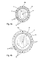
- Fig. 4a shows the inner magnet carrier 15 with the introduced permanent magnet 2 in plan view.
- the inner magnetic carrier 15 aligns the introduced permanent magnets 2 to form a Halbach array whose magnetic field 3 extends outside the inner magnetic carrier 15 substantially into the cylindrical inner space of the inner magnetic carrier 15 and is homogeneous in the medium 6.
- Fig. 4b shows the outer magnet carrier 19 with the introduced permanent magnet 2 in plan view.
- the outer magnetic carrier 19 also aligns the introduced permanent magnets 2 to form a Halbach array, the magnetic field 4 of which extends outside the outer magnetic carrier 19 essentially into the cylindrical inner space of the outer magnetic carrier 19 and is homogeneous in the medium 6.
- the two Halbach arrays are matched to one another such that the magnitudes of the field strengths of the magnetic field 3 and the magnetic field 4 in the medium 6 are equal. Due to the fact that the magnetic field 3 does not substantially extend into the outer space of the inner support 15, essentially only the friction of the radial sliding bearings and the axial sliding bearings is to be overcome for rotating the outer support 12.
- Fig. 5a shows the inner magnet carrier 15 and the outer magnet carrier 19 with the introduced permanent magnet 2 in a first orientation to each other.
- the magnetic field 3 and the magnetic field 4 are aligned parallel to each other.
- the magnetic field strength of the superimposed magnetic field is therefore twice as large as the magnetic field strength of the magnetic field 3 or 4 of the magnetic field considered in isolation.
- Fig. 5b shows the inner magnet carrier 15 and the outer magnet carrier 19 with the introduced Permanent magnet 2 in a second orientation to each other.
- the magnetic field 3 and the magnetic field 4 are aligned in anti-parallel to each other.
- no magnetic field is present. If no magnetic field in the medium 6 is mentioned here, this does not exclude a magnetic field with a low magnetic field strength present in the medium 6. However, the remaining magnetic field strength is so low that the desired measurement accuracy is achieved.
- the three magnetization segments 9 of the magnetization device 1, see Fig. 1a are aligned with each other such that their segment axes of rotation 14 coincide with the longitudinal axis 8 of the measuring tube 5.
- the inner supports 10 are oriented relative to each other such that their magnetic fields 3 are parallel.
- Each of the outer supports 12 is rotatable independently of the other outer supports 12 about the longitudinal axis 8 of the measuring tube 5, and a rotation of each of the outer support 12 is effected by an - not visible in the figures - actuator.
- the actuators can set arbitrary orientations of the outer supports 12 with respect to the inner supports 10.
- the three outer supports 12 are always oriented relative to one another by the actuators such that the magnetic fields 4 are parallel to one another. Accordingly, rotations of the three outer supports 12 take place together and uniformly with respect to the inner supports 10.
- the magnetic field 3, 4 in the medium 6 via the magnetization path 7 set to arbitrary magnetic field strengths between zero and twice the magnetic field strength of the magnetic field 3 or the magnetic field 4 considered.
- the magnetic field 3, 4 in the medium 6 has only a single direction over the magnetization path 7.
- the magnetic field strength of the magnetic field 3, 4 in the medium 6 is constant along the magnetization path 7 along any line parallel to the longitudinal axis 8 of the measuring tube 5.
- the magnetic field 3, 4 on the magnetization path 7 is homogeneous.
- the outer supports 12 of the three magnetization segments 9 become independent of one another oriented. Only two different orientations of each of the outer supports 12 with respect to its inner support 10 are set. In the first orientation, the magnetic field 3 and the magnetic field 4 of the respective magnetization segment 9 are aligned in parallel. The magnetic field strength of the magnetic field 3, 4 in the medium 6 is considered twice the magnetic field strength of the magnetic field 3 or the magnetic field 4 in itself. In the second orientation, the magnetic field 3 and the magnetic field 4 are aligned in anti-parallel. The magnetic field strength 3, 4 in the medium 6 is zero. In the case of the magnetizations of the medium 6 that can be generated by this method, the magnetization always takes place with the same magnetic field strength in the medium 6. The magnetic field 3, 4 in the medium 6 has only a single one regardless of the orientations of the outer supports 12 of the individual magnetization segments 9 via the magnetization path 7 Direction up.
Landscapes
- Physics & Mathematics (AREA)
- Fluid Mechanics (AREA)
- General Physics & Mathematics (AREA)
- Measuring Volume Flow (AREA)
- Magnetic Resonance Imaging Apparatus (AREA)
Applications Claiming Priority (1)
| Application Number | Priority Date | Filing Date | Title |
|---|---|---|---|
| DE102012013935.7A DE102012013935A1 (de) | 2012-07-16 | 2012-07-16 | Magnetisierungsvorrichtung und Verfahren zum Betreiben einer Magnetisierungsvorrichtung |
Publications (3)
| Publication Number | Publication Date |
|---|---|
| EP2687825A2 true EP2687825A2 (fr) | 2014-01-22 |
| EP2687825A3 EP2687825A3 (fr) | 2015-06-24 |
| EP2687825B1 EP2687825B1 (fr) | 2020-08-26 |
Family
ID=48782126
Family Applications (1)
| Application Number | Title | Priority Date | Filing Date |
|---|---|---|---|
| EP13003370.7A Active EP2687825B1 (fr) | 2012-07-16 | 2013-07-03 | Débitmètre à noyau magnétique |
Country Status (14)
| Country | Link |
|---|---|
| US (1) | US9429456B2 (fr) |
| EP (1) | EP2687825B1 (fr) |
| JP (1) | JP6198497B2 (fr) |
| KR (1) | KR102031217B1 (fr) |
| CN (1) | CN103542899B (fr) |
| AR (1) | AR091761A1 (fr) |
| AU (1) | AU2013206720B2 (fr) |
| BR (1) | BR102013018079A2 (fr) |
| CA (1) | CA2820828C (fr) |
| DE (1) | DE102012013935A1 (fr) |
| MX (1) | MX2013008206A (fr) |
| MY (1) | MY172631A (fr) |
| RU (1) | RU2606546C2 (fr) |
| SA (1) | SA113340718B1 (fr) |
Cited By (1)
| Publication number | Priority date | Publication date | Assignee | Title |
|---|---|---|---|---|
| US12228437B2 (en) | 2022-09-01 | 2025-02-18 | Saudi Arabian Oil Company | Multiphase flow meter |
Families Citing this family (19)
| Publication number | Priority date | Publication date | Assignee | Title |
|---|---|---|---|---|
| US9395222B2 (en) * | 2011-11-20 | 2016-07-19 | Krohne Ag | Magnetization device for a nuclear magnetic flow meter |
| US10174569B2 (en) | 2013-06-20 | 2019-01-08 | Aspect International (2015) Private Limited | NMR/MRI-based integrated system for analyzing and treating of a drilling mud for drilling mud recycling process and methods thereof |
| US9494503B2 (en) | 2013-11-06 | 2016-11-15 | Aspect Imaging Ltd. | Inline rheology/viscosity, density, and flow rate measurement |
| DE102015001161A1 (de) * | 2014-08-29 | 2016-03-03 | Krohne Ag | Verfahren zum Betreiben eines kernmagnetischen Durchflussmessgeräts und kernmagnetisches Durchflussmessgerät |
| DE102015005300A1 (de) * | 2014-11-27 | 2016-06-02 | Krohne Ag | Verfahren zum Betreiben eines kernmagnetischen Durchflussmessgeräts |
| US10436619B2 (en) * | 2015-01-16 | 2019-10-08 | Sanofi-Aventis Deutschland Gmbh | Flow rate sensor |
| US10670574B2 (en) | 2015-01-19 | 2020-06-02 | Aspect International (2015) Private Limited | NMR-based systems for crude oil enhancement and methods thereof |
| CN106053299B (zh) | 2015-04-12 | 2020-10-30 | 艾斯拜克特Ai有限公司 | 非圆形横截面管道中的流体的nmr成像 |
| CN106324010A (zh) | 2015-07-02 | 2017-01-11 | 艾斯拜克特Ai有限公司 | 使用mr设备对在管道中流动的流体的分析 |
| US10655996B2 (en) | 2016-04-12 | 2020-05-19 | Aspect Imaging Ltd. | System and method for measuring velocity profiles |
| DE102016109993A1 (de) * | 2016-05-31 | 2017-11-30 | Krohne Ag | Verfahren zum Betreiben eines kernmagnetischen Durchflussmessgeräts und kernmagnetisches Durchflussmessgerät |
| WO2018187825A1 (fr) * | 2017-04-13 | 2018-10-18 | The University Of Queensland | Agencement d'aimant de mesure |
| US11460330B2 (en) | 2020-07-06 | 2022-10-04 | Saudi Arabian Oil Company | Reducing noise in a vortex flow meter |
| CN111759306B (zh) * | 2020-08-04 | 2023-11-24 | 重庆邮电大学 | 一种单边磁粒子成像检测装置 |
| US11428557B2 (en) | 2020-08-31 | 2022-08-30 | Saudi Arabian Oil Company | Determining fluid properties |
| US11525723B2 (en) | 2020-08-31 | 2022-12-13 | Saudi Arabian Oil Company | Determining fluid properties |
| US11549836B2 (en) | 2021-05-26 | 2023-01-10 | Saudi Arabian Oil Company | Liquid NMR signal boost during NMR flow metering of wet gas flow using enhanced signal relaxation and/or dynamic nuclear polarisation using immobilised radicals |
| RU207846U1 (ru) * | 2021-09-06 | 2021-11-19 | ООО "Мехатрон сервис" | Электромагнитный расходомер |
| CN119642910B (zh) * | 2023-09-15 | 2026-04-28 | 中国石油天然气股份有限公司 | 磁共振流量计探头结构 |
Citations (1)
| Publication number | Priority date | Publication date | Assignee | Title |
|---|---|---|---|---|
| US20080174309A1 (en) | 2006-11-29 | 2008-07-24 | Spinlock Srl | Magnetic resonance based apparatus and method to analyze and to measure the bi-directional flow regime in a transport or a production conduit of complex fluids, in real time and real flow-rate |
Family Cites Families (16)
| Publication number | Priority date | Publication date | Assignee | Title |
|---|---|---|---|---|
| US4782295A (en) * | 1987-06-01 | 1988-11-01 | Lew Hyok S | Nuclear magnetic resonance flowmeter |
| US4862128A (en) * | 1989-04-27 | 1989-08-29 | The United States Of America As Represented By The Secretary Of The Army | Field adjustable transverse flux sources |
| GB2291198B (en) * | 1994-07-06 | 1999-01-13 | Alwin Bayer | Detection of magnetised fluid flows |
| RU2152006C1 (ru) * | 1998-03-12 | 2000-06-27 | ТОО "Фирма "Юстас" | Ядерно-магнитный расходомер для многофазной среды |
| US6535092B1 (en) * | 1999-09-21 | 2003-03-18 | Magnetic Solutions (Holdings) Limited | Device for generating a variable magnetic field |
| US6320488B1 (en) * | 2000-07-31 | 2001-11-20 | The United States Of America As Represented By The Secretary Of The Army | Magic cylinder adjustable in field strength |
| US6577125B2 (en) * | 2000-12-18 | 2003-06-10 | Halliburton Energy Services, Inc. | Temperature compensated magnetic field apparatus for NMR measurements |
| US6737864B2 (en) * | 2001-03-28 | 2004-05-18 | Halliburton Energy Services, Inc. | Magnetic resonance fluid analysis apparatus and method |
| US8248067B2 (en) * | 2004-09-24 | 2012-08-21 | Baker Hughes Incorporated | Apparatus and methods for estimating downhole fluid compositions |
| GB0421266D0 (en) * | 2004-09-24 | 2004-10-27 | Quantx Wellbore Instrumentatio | Measurement apparatus and method |
| US6989730B1 (en) * | 2005-05-24 | 2006-01-24 | The United States Of America As Represented By The Secretary Of The Army | Adjustable toroidal magnet |
| DE102006031425A1 (de) * | 2006-07-05 | 2008-01-10 | Forschungszentrum Jülich GmbH | Magnetsystem mit variabler Feldstärke |
| DE102006032896A1 (de) * | 2006-07-15 | 2008-01-17 | Fachhochschule Kiel | Magnetisch-induktiver Durchflussmesser |
| KR20100099054A (ko) * | 2009-03-02 | 2010-09-10 | 신에쓰 가가꾸 고교 가부시끼가이샤 | 영구 자석식 자계 발생 장치 |
| DE102014010324B3 (de) * | 2014-05-23 | 2015-02-05 | Krohne Ag | Kernmagnetisches Durchflussmessgerät und Verfahren zum Betreiben eines kernmagnetischen Durchflussmessgeräts |
| DE102014015943B3 (de) * | 2014-07-10 | 2015-07-09 | Krohne Ag | Verfahren zum Betreiben eines kernmagnetischen Durchflussmessgeräts |
-
2012
- 2012-07-16 DE DE102012013935.7A patent/DE102012013935A1/de not_active Ceased
-
2013
- 2013-07-03 EP EP13003370.7A patent/EP2687825B1/fr active Active
- 2013-07-05 AU AU2013206720A patent/AU2013206720B2/en not_active Ceased
- 2013-07-11 CA CA2820828A patent/CA2820828C/fr not_active Expired - Fee Related
- 2013-07-11 MY MYPI2013701215A patent/MY172631A/en unknown
- 2013-07-15 AR ARP130102504 patent/AR091761A1/es active IP Right Grant
- 2013-07-15 BR BRBR102013018079-3A patent/BR102013018079A2/pt not_active IP Right Cessation
- 2013-07-15 SA SA113340718A patent/SA113340718B1/ar unknown
- 2013-07-15 MX MX2013008206A patent/MX2013008206A/es active IP Right Grant
- 2013-07-15 RU RU2013132613A patent/RU2606546C2/ru active
- 2013-07-15 KR KR1020130082828A patent/KR102031217B1/ko not_active Expired - Fee Related
- 2013-07-16 JP JP2013147874A patent/JP6198497B2/ja not_active Expired - Fee Related
- 2013-07-16 CN CN201310297215.XA patent/CN103542899B/zh not_active Expired - Fee Related
- 2013-07-16 US US13/943,108 patent/US9429456B2/en active Active
Patent Citations (1)
| Publication number | Priority date | Publication date | Assignee | Title |
|---|---|---|---|---|
| US20080174309A1 (en) | 2006-11-29 | 2008-07-24 | Spinlock Srl | Magnetic resonance based apparatus and method to analyze and to measure the bi-directional flow regime in a transport or a production conduit of complex fluids, in real time and real flow-rate |
Cited By (1)
| Publication number | Priority date | Publication date | Assignee | Title |
|---|---|---|---|---|
| US12228437B2 (en) | 2022-09-01 | 2025-02-18 | Saudi Arabian Oil Company | Multiphase flow meter |
Also Published As
| Publication number | Publication date |
|---|---|
| JP2014021118A (ja) | 2014-02-03 |
| JP6198497B2 (ja) | 2017-09-20 |
| CA2820828A1 (fr) | 2014-01-16 |
| US9429456B2 (en) | 2016-08-30 |
| EP2687825A3 (fr) | 2015-06-24 |
| DE102012013935A1 (de) | 2014-01-16 |
| CN103542899A (zh) | 2014-01-29 |
| AU2013206720A1 (en) | 2014-01-30 |
| RU2606546C2 (ru) | 2017-01-10 |
| SA113340718B1 (ar) | 2016-08-17 |
| KR20140010341A (ko) | 2014-01-24 |
| CA2820828C (fr) | 2018-12-11 |
| KR102031217B1 (ko) | 2019-10-11 |
| CN103542899B (zh) | 2018-03-13 |
| RU2013132613A (ru) | 2015-01-20 |
| EP2687825B1 (fr) | 2020-08-26 |
| MX2013008206A (es) | 2014-01-21 |
| BR102013018079A2 (pt) | 2015-06-30 |
| MY172631A (en) | 2019-12-06 |
| US20140028310A1 (en) | 2014-01-30 |
| AU2013206720B2 (en) | 2019-03-14 |
| AR091761A1 (es) | 2015-02-25 |
Similar Documents
| Publication | Publication Date | Title |
|---|---|---|
| EP2687825B1 (fr) | Débitmètre à noyau magnétique | |
| DE102014010324B3 (de) | Kernmagnetisches Durchflussmessgerät und Verfahren zum Betreiben eines kernmagnetischen Durchflussmessgeräts | |
| EP2604983B1 (fr) | Dispositif de magnétisation pour un appareil de mesure de débit à noyau magnétique | |
| DE2809237A1 (de) | Signalgeber fuer kernmagnetische resonanz | |
| EP3356693B1 (fr) | Palier, en particulier pour un ensemble de sustentation magnétique | |
| DE3333755A1 (de) | Magneteinrichtung einer anlage der kernspin-tomographie mit einer abschirmvorrichtung | |
| EP3036511B1 (fr) | Débitmètre nucléaire magnétique et procédé permettant de faire fonctionner des débitmètres nucléaires magnétiques | |
| DE102008033886A1 (de) | Apparatur zur Durchführung von DNP-NMR Messungen mit Kompensationsanordnung, sowie Verfahren zur Auslegung der Kompensationsanordnung | |
| EP2910907A1 (fr) | Débitmètre doté d'un dispositif de mesure convertissant un principe de mesure tomographique | |
| EP3614162A1 (fr) | Dispositif aimant permanent permettant de générer un champ homogène (« 3d halbach ») | |
| DE102012016402B4 (de) | Magnetbaugruppe für ein kernmagnetisches Druchflussmessgerät | |
| EP2169356B1 (fr) | Dispositif de détermination de la position axiale du rotor d'un moteur linéaire | |
| EP2840410B1 (fr) | Dispositif d'homogénéisation d'un champ magnétique | |
| DE68915751T2 (de) | Vorrichtung zur Erzeugung eines Magnetfeldes für ein Elektronspinresonanzsystem. | |
| EP0177869B1 (fr) | Aménagement d'un aimant avec un dispositif d'écran pour une installation de tomographie de spin nucléaire | |
| DE19912428C2 (de) | Kernspinresonanzgerät | |
| WO1991011731A2 (fr) | Debitmetre inductif | |
| DE60009182T2 (de) | Drehkupplung für die magnetische Anordnung von zwei Bauteilen, einem Kraftbauteil und einem Arbeitsbauteil | |
| DE2929404C2 (de) | Differenzfeldsonde | |
| EP0184656A1 (fr) | Dispositif magnétique pour la tomographie à résonance de spin nucléaire comportant une structure de blindage à forme approximativement cylindrique | |
| DE102019115339B4 (de) | Sensorvorrichtung zur Messung von Wechselströmen mit einem verbesserten Schließmechanismus | |
| DE421129C (de) | Elektrischer Messapparat mit beweglichen Eisenmassen | |
| DE10004765A1 (de) | MR-Gerät mit einer Gradientenspulen-Anordnung | |
| DE1498482A1 (de) | Induktions-Durchflussmesser | |
| EP2315044B1 (fr) | Sonde de magnétomètre différentiel |
Legal Events
| Date | Code | Title | Description |
|---|---|---|---|
| PUAI | Public reference made under article 153(3) epc to a published international application that has entered the european phase |
Free format text: ORIGINAL CODE: 0009012 |
|
| AK | Designated contracting states |
Kind code of ref document: A2 Designated state(s): AL AT BE BG CH CY CZ DE DK EE ES FI FR GB GR HR HU IE IS IT LI LT LU LV MC MK MT NL NO PL PT RO RS SE SI SK SM TR |
|
| AX | Request for extension of the european patent |
Extension state: BA ME |
|
| PUAL | Search report despatched |
Free format text: ORIGINAL CODE: 0009013 |
|
| AK | Designated contracting states |
Kind code of ref document: A3 Designated state(s): AL AT BE BG CH CY CZ DE DK EE ES FI FR GB GR HR HU IE IS IT LI LT LU LV MC MK MT NL NO PL PT RO RS SE SI SK SM TR |
|
| AX | Request for extension of the european patent |
Extension state: BA ME |
|
| RIC1 | Information provided on ipc code assigned before grant |
Ipc: G01F 1/56 20060101AFI20150520BHEP Ipc: G01F 1/716 20060101ALI20150520BHEP |
|
| 17P | Request for examination filed |
Effective date: 20151222 |
|
| RBV | Designated contracting states (corrected) |
Designated state(s): AL AT BE BG CH CY CZ DE DK EE ES FI FR GB GR HR HU IE IS IT LI LT LU LV MC MK MT NL NO PL PT RO RS SE SI SK SM TR |
|
| STAA | Information on the status of an ep patent application or granted ep patent |
Free format text: STATUS: EXAMINATION IS IN PROGRESS |
|
| 17Q | First examination report despatched |
Effective date: 20190117 |
|
| GRAP | Despatch of communication of intention to grant a patent |
Free format text: ORIGINAL CODE: EPIDOSNIGR1 |
|
| STAA | Information on the status of an ep patent application or granted ep patent |
Free format text: STATUS: GRANT OF PATENT IS INTENDED |
|
| GRAS | Grant fee paid |
Free format text: ORIGINAL CODE: EPIDOSNIGR3 |
|
| INTG | Intention to grant announced |
Effective date: 20200226 |
|
| GRAA | (expected) grant |
Free format text: ORIGINAL CODE: 0009210 |
|
| STAA | Information on the status of an ep patent application or granted ep patent |
Free format text: STATUS: THE PATENT HAS BEEN GRANTED |
|
| AK | Designated contracting states |
Kind code of ref document: B1 Designated state(s): AL AT BE BG CH CY CZ DE DK EE ES FI FR GB GR HR HU IE IS IT LI LT LU LV MC MK MT NL NO PL PT RO RS SE SI SK SM TR |
|
| REG | Reference to a national code |
Ref country code: GB Ref legal event code: FG4D Free format text: NOT ENGLISH |
|
| REG | Reference to a national code |
Ref country code: CH Ref legal event code: EP |
|
| REG | Reference to a national code |
Ref country code: DE Ref legal event code: R096 Ref document number: 502013015051 Country of ref document: DE |
|
| REG | Reference to a national code |
Ref country code: AT Ref legal event code: REF Ref document number: 1306807 Country of ref document: AT Kind code of ref document: T Effective date: 20200915 |
|
| REG | Reference to a national code |
Ref country code: IE Ref legal event code: FG4D Free format text: LANGUAGE OF EP DOCUMENT: GERMAN |
|
| REG | Reference to a national code |
Ref country code: NL Ref legal event code: FP |
|
| REG | Reference to a national code |
Ref country code: LT Ref legal event code: MG4D |
|
| PG25 | Lapsed in a contracting state [announced via postgrant information from national office to epo] |
Ref country code: SE Free format text: LAPSE BECAUSE OF FAILURE TO SUBMIT A TRANSLATION OF THE DESCRIPTION OR TO PAY THE FEE WITHIN THE PRESCRIBED TIME-LIMIT Effective date: 20200826 Ref country code: HR Free format text: LAPSE BECAUSE OF FAILURE TO SUBMIT A TRANSLATION OF THE DESCRIPTION OR TO PAY THE FEE WITHIN THE PRESCRIBED TIME-LIMIT Effective date: 20200826 Ref country code: FI Free format text: LAPSE BECAUSE OF FAILURE TO SUBMIT A TRANSLATION OF THE DESCRIPTION OR TO PAY THE FEE WITHIN THE PRESCRIBED TIME-LIMIT Effective date: 20200826 Ref country code: BG Free format text: LAPSE BECAUSE OF FAILURE TO SUBMIT A TRANSLATION OF THE DESCRIPTION OR TO PAY THE FEE WITHIN THE PRESCRIBED TIME-LIMIT Effective date: 20201126 Ref country code: LT Free format text: LAPSE BECAUSE OF FAILURE TO SUBMIT A TRANSLATION OF THE DESCRIPTION OR TO PAY THE FEE WITHIN THE PRESCRIBED TIME-LIMIT Effective date: 20200826 Ref country code: GR Free format text: LAPSE BECAUSE OF FAILURE TO SUBMIT A TRANSLATION OF THE DESCRIPTION OR TO PAY THE FEE WITHIN THE PRESCRIBED TIME-LIMIT Effective date: 20201127 Ref country code: PT Free format text: LAPSE BECAUSE OF FAILURE TO SUBMIT A TRANSLATION OF THE DESCRIPTION OR TO PAY THE FEE WITHIN THE PRESCRIBED TIME-LIMIT Effective date: 20201228 |
|
| REG | Reference to a national code |
Ref country code: NO Ref legal event code: T2 Effective date: 20200826 |
|
| PG25 | Lapsed in a contracting state [announced via postgrant information from national office to epo] |
Ref country code: IS Free format text: LAPSE BECAUSE OF FAILURE TO SUBMIT A TRANSLATION OF THE DESCRIPTION OR TO PAY THE FEE WITHIN THE PRESCRIBED TIME-LIMIT Effective date: 20201226 Ref country code: PL Free format text: LAPSE BECAUSE OF FAILURE TO SUBMIT A TRANSLATION OF THE DESCRIPTION OR TO PAY THE FEE WITHIN THE PRESCRIBED TIME-LIMIT Effective date: 20200826 Ref country code: RS Free format text: LAPSE BECAUSE OF FAILURE TO SUBMIT A TRANSLATION OF THE DESCRIPTION OR TO PAY THE FEE WITHIN THE PRESCRIBED TIME-LIMIT Effective date: 20200826 Ref country code: LV Free format text: LAPSE BECAUSE OF FAILURE TO SUBMIT A TRANSLATION OF THE DESCRIPTION OR TO PAY THE FEE WITHIN THE PRESCRIBED TIME-LIMIT Effective date: 20200826 |
|
| PG25 | Lapsed in a contracting state [announced via postgrant information from national office to epo] |
Ref country code: CZ Free format text: LAPSE BECAUSE OF FAILURE TO SUBMIT A TRANSLATION OF THE DESCRIPTION OR TO PAY THE FEE WITHIN THE PRESCRIBED TIME-LIMIT Effective date: 20200826 Ref country code: EE Free format text: LAPSE BECAUSE OF FAILURE TO SUBMIT A TRANSLATION OF THE DESCRIPTION OR TO PAY THE FEE WITHIN THE PRESCRIBED TIME-LIMIT Effective date: 20200826 Ref country code: DK Free format text: LAPSE BECAUSE OF FAILURE TO SUBMIT A TRANSLATION OF THE DESCRIPTION OR TO PAY THE FEE WITHIN THE PRESCRIBED TIME-LIMIT Effective date: 20200826 Ref country code: SM Free format text: LAPSE BECAUSE OF FAILURE TO SUBMIT A TRANSLATION OF THE DESCRIPTION OR TO PAY THE FEE WITHIN THE PRESCRIBED TIME-LIMIT Effective date: 20200826 Ref country code: RO Free format text: LAPSE BECAUSE OF FAILURE TO SUBMIT A TRANSLATION OF THE DESCRIPTION OR TO PAY THE FEE WITHIN THE PRESCRIBED TIME-LIMIT Effective date: 20200826 |
|
| REG | Reference to a national code |
Ref country code: DE Ref legal event code: R097 Ref document number: 502013015051 Country of ref document: DE |
|
| PG25 | Lapsed in a contracting state [announced via postgrant information from national office to epo] |
Ref country code: AL Free format text: LAPSE BECAUSE OF FAILURE TO SUBMIT A TRANSLATION OF THE DESCRIPTION OR TO PAY THE FEE WITHIN THE PRESCRIBED TIME-LIMIT Effective date: 20200826 Ref country code: ES Free format text: LAPSE BECAUSE OF FAILURE TO SUBMIT A TRANSLATION OF THE DESCRIPTION OR TO PAY THE FEE WITHIN THE PRESCRIBED TIME-LIMIT Effective date: 20200826 |
|
| PG25 | Lapsed in a contracting state [announced via postgrant information from national office to epo] |
Ref country code: SK Free format text: LAPSE BECAUSE OF FAILURE TO SUBMIT A TRANSLATION OF THE DESCRIPTION OR TO PAY THE FEE WITHIN THE PRESCRIBED TIME-LIMIT Effective date: 20200826 |
|
| PLBE | No opposition filed within time limit |
Free format text: ORIGINAL CODE: 0009261 |
|
| STAA | Information on the status of an ep patent application or granted ep patent |
Free format text: STATUS: NO OPPOSITION FILED WITHIN TIME LIMIT |
|
| 26N | No opposition filed |
Effective date: 20210527 |
|
| PG25 | Lapsed in a contracting state [announced via postgrant information from national office to epo] |
Ref country code: SI Free format text: LAPSE BECAUSE OF FAILURE TO SUBMIT A TRANSLATION OF THE DESCRIPTION OR TO PAY THE FEE WITHIN THE PRESCRIBED TIME-LIMIT Effective date: 20200826 |
|
| REG | Reference to a national code |
Ref country code: CH Ref legal event code: PL |
|
| PG25 | Lapsed in a contracting state [announced via postgrant information from national office to epo] |
Ref country code: MC Free format text: LAPSE BECAUSE OF FAILURE TO SUBMIT A TRANSLATION OF THE DESCRIPTION OR TO PAY THE FEE WITHIN THE PRESCRIBED TIME-LIMIT Effective date: 20200826 |
|
| REG | Reference to a national code |
Ref country code: BE Ref legal event code: MM Effective date: 20210731 |
|
| PG25 | Lapsed in a contracting state [announced via postgrant information from national office to epo] |
Ref country code: LI Free format text: LAPSE BECAUSE OF NON-PAYMENT OF DUE FEES Effective date: 20210731 Ref country code: CH Free format text: LAPSE BECAUSE OF NON-PAYMENT OF DUE FEES Effective date: 20210731 |
|
| PG25 | Lapsed in a contracting state [announced via postgrant information from national office to epo] |
Ref country code: LU Free format text: LAPSE BECAUSE OF NON-PAYMENT OF DUE FEES Effective date: 20210703 |
|
| PG25 | Lapsed in a contracting state [announced via postgrant information from national office to epo] |
Ref country code: IE Free format text: LAPSE BECAUSE OF NON-PAYMENT OF DUE FEES Effective date: 20210703 Ref country code: BE Free format text: LAPSE BECAUSE OF NON-PAYMENT OF DUE FEES Effective date: 20210731 |
|
| REG | Reference to a national code |
Ref country code: AT Ref legal event code: MM01 Ref document number: 1306807 Country of ref document: AT Kind code of ref document: T Effective date: 20210703 |
|
| PG25 | Lapsed in a contracting state [announced via postgrant information from national office to epo] |
Ref country code: AT Free format text: LAPSE BECAUSE OF NON-PAYMENT OF DUE FEES Effective date: 20210703 |
|
| PG25 | Lapsed in a contracting state [announced via postgrant information from national office to epo] |
Ref country code: HU Free format text: LAPSE BECAUSE OF FAILURE TO SUBMIT A TRANSLATION OF THE DESCRIPTION OR TO PAY THE FEE WITHIN THE PRESCRIBED TIME-LIMIT; INVALID AB INITIO Effective date: 20130703 |
|
| PG25 | Lapsed in a contracting state [announced via postgrant information from national office to epo] |
Ref country code: CY Free format text: LAPSE BECAUSE OF FAILURE TO SUBMIT A TRANSLATION OF THE DESCRIPTION OR TO PAY THE FEE WITHIN THE PRESCRIBED TIME-LIMIT Effective date: 20200826 |
|
| P01 | Opt-out of the competence of the unified patent court (upc) registered |
Effective date: 20230607 |
|
| PG25 | Lapsed in a contracting state [announced via postgrant information from national office to epo] |
Ref country code: MK Free format text: LAPSE BECAUSE OF FAILURE TO SUBMIT A TRANSLATION OF THE DESCRIPTION OR TO PAY THE FEE WITHIN THE PRESCRIBED TIME-LIMIT Effective date: 20200826 |
|
| PG25 | Lapsed in a contracting state [announced via postgrant information from national office to epo] |
Ref country code: TR Free format text: LAPSE BECAUSE OF FAILURE TO SUBMIT A TRANSLATION OF THE DESCRIPTION OR TO PAY THE FEE WITHIN THE PRESCRIBED TIME-LIMIT Effective date: 20200826 |
|
| PGFP | Annual fee paid to national office [announced via postgrant information from national office to epo] |
Ref country code: NL Payment date: 20240719 Year of fee payment: 12 |
|
| PG25 | Lapsed in a contracting state [announced via postgrant information from national office to epo] |
Ref country code: MT Free format text: LAPSE BECAUSE OF FAILURE TO SUBMIT A TRANSLATION OF THE DESCRIPTION OR TO PAY THE FEE WITHIN THE PRESCRIBED TIME-LIMIT Effective date: 20200826 |
|
| PGFP | Annual fee paid to national office [announced via postgrant information from national office to epo] |
Ref country code: DE Payment date: 20240924 Year of fee payment: 12 |
|
| PGFP | Annual fee paid to national office [announced via postgrant information from national office to epo] |
Ref country code: GB Payment date: 20240722 Year of fee payment: 12 |
|
| PGFP | Annual fee paid to national office [announced via postgrant information from national office to epo] |
Ref country code: FR Payment date: 20240730 Year of fee payment: 12 |
|
| PGFP | Annual fee paid to national office [announced via postgrant information from national office to epo] |
Ref country code: NO Payment date: 20240723 Year of fee payment: 12 Ref country code: IT Payment date: 20240725 Year of fee payment: 12 |
|
| REG | Reference to a national code |
Ref country code: DE Ref legal event code: R119 Ref document number: 502013015051 Country of ref document: DE |
|
| REG | Reference to a national code |
Ref country code: NL Ref legal event code: MM Effective date: 20250801 |
|
| GBPC | Gb: european patent ceased through non-payment of renewal fee |
Effective date: 20250703 |
|
| PG25 | Lapsed in a contracting state [announced via postgrant information from national office to epo] |
Ref country code: GB Free format text: LAPSE BECAUSE OF NON-PAYMENT OF DUE FEES Effective date: 20250703 |
|
| PG25 | Lapsed in a contracting state [announced via postgrant information from national office to epo] |
Ref country code: DE Free format text: LAPSE BECAUSE OF NON-PAYMENT OF DUE FEES Effective date: 20260203 Ref country code: NO Free format text: LAPSE BECAUSE OF NON-PAYMENT OF DUE FEES Effective date: 20250731 |
|
| PG25 | Lapsed in a contracting state [announced via postgrant information from national office to epo] |
Ref country code: NL Free format text: LAPSE BECAUSE OF NON-PAYMENT OF DUE FEES Effective date: 20250801 |
|
| PG25 | Lapsed in a contracting state [announced via postgrant information from national office to epo] |
Ref country code: FR Free format text: LAPSE BECAUSE OF NON-PAYMENT OF DUE FEES Effective date: 20250731 |