EP2687860B1 - Richtungs-Erkennung eines empfindlichen Mittelspannungs-Erdschlusses durch lineare Korrelation - Google Patents
Richtungs-Erkennung eines empfindlichen Mittelspannungs-Erdschlusses durch lineare Korrelation Download PDFInfo
- Publication number
- EP2687860B1 EP2687860B1 EP13172415.5A EP13172415A EP2687860B1 EP 2687860 B1 EP2687860 B1 EP 2687860B1 EP 13172415 A EP13172415 A EP 13172415A EP 2687860 B1 EP2687860 B1 EP 2687860B1
- Authority
- EP
- European Patent Office
- Prior art keywords
- current
- mem
- fault
- network
- representative
- Prior art date
- Legal status (The legal status is an assumption and is not a legal conclusion. Google has not performed a legal analysis and makes no representation as to the accuracy of the status listed.)
- Active
Links
Images


Classifications
-
- H—ELECTRICITY
- H02—GENERATION; CONVERSION OR DISTRIBUTION OF ELECTRIC POWER
- H02H—EMERGENCY PROTECTIVE CIRCUIT ARRANGEMENTS
- H02H1/00—Details of emergency protective circuit arrangements
- H02H1/0061—Details of emergency protective circuit arrangements concerning transmission of signals
-
- G—PHYSICS
- G01—MEASURING; TESTING
- G01R—MEASURING ELECTRIC VARIABLES; MEASURING MAGNETIC VARIABLES
- G01R31/00—Arrangements for testing electric properties; Arrangements for locating electric faults; Arrangements for electrical testing characterised by what is being tested not provided for elsewhere
- G01R31/08—Locating faults in cables, transmission lines, or networks
- G01R31/088—Aspects of digital computing
-
- H—ELECTRICITY
- H02—GENERATION; CONVERSION OR DISTRIBUTION OF ELECTRIC POWER
- H02H—EMERGENCY PROTECTIVE CIRCUIT ARRANGEMENTS
- H02H5/00—Emergency protective circuit arrangements for automatic disconnection directly responsive to an undesired change from normal non-electric working conditions with or without subsequent reconnection
- H02H5/10—Emergency protective circuit arrangements for automatic disconnection directly responsive to an undesired change from normal non-electric working conditions with or without subsequent reconnection responsive to mechanical injury, e.g. rupture of line, breakage of earth connection
Definitions
- the invention relates to fault detection on an electrical distribution network, in particular medium voltage.
- the invention proposes a principle for detecting resistant faults between a medium-voltage electrical conductor and earth, a defect for example caused by the breaking of said conductor, as well as a suitable device.
- Parameters resulting from the processing of the only signals representative of the currents of each phase of the network allow the directional localization, without using values representing the voltage between phases, nor representative values of the simple voltages.
- the invention also relates to a fault signaling device and a tripping relay comprising current sensors associated with each phase of the network and supplying the preceding detection device with the signals enabling the signaling, for example by light, or the triggering of a cut-off device of the network.
- Ground fault detection devices are particularly used in medium-voltage three-phase electrical distribution networks.
- distribution networks 1 can be broken down into different levels, with a first very high voltage and high voltage distribution and distribution network 2 THT / HT (from 35 to more than 200 kV), used to transport or distribute electrical energy from production plants over long distances.
- a three-phase transformer 3 serves a medium voltage MV distribution network 4, usually between 1 and 35 kV, more precisely 11 kV single voltage in France, for smaller scale transport, to customers of industrial type or substations transforming the average low voltage LV (in particular 0.4 kV in France).
- the main line thus feeds start lines 5, 5 ', composed of overhead lines and / or underground cables, some of which may comprise at the head a circuit breaker or other cut-off device 6 protecting them.
- start lines 5, 5 ' composed of overhead lines and / or underground cables, some of which may comprise at the head a circuit breaker or other cut-off device 6 protecting them.
- the network 4 is subject to various defects, which it is important to detect and locate in order to overcome the problems generated: power failure, degradation of the behavior of the insulation materials, not to mention the peoples' security.
- the most common are the single-phase faults 7, located outside the source station, in which a phase is in contact with the ground, or the rupture of an aerial cable in case of bad weather in particular.
- the starting lines 5 ', or line sections 5, may then comprise a device 8 for detecting an earth fault.
- the device 8 can serve as a fault passing indicator, for example lighting a light indicator; a device 8 1 may also be associated or integrated with a protective relay 9 adapted to control the opening of the contacts of the circuit breaker 6.
- An option for detecting this type of fault 7 is to measure the current flowing, or parameters relating to it. These measurements are however supplemented by measurements on the three-phase voltages, if we want to give the relative direction (upstream or downstream) with respect to the fault detection equipment.
- the voltage MT of the network 4 generates a complication in the access to the measurement points, and problems of isolation of the electronic equipment: this type of directional detection is difficult to implement.
- the directional detection of a ground fault in a multiphase network is based on the dispersion of unsigned linear correlation factors between the phase currents and the zero sequence current.
- the use of mean and standard deviation of this correlation coefficient makes it possible to determine whether the defect is upstream or downstream of the measurement of the phase current sensors of the detectors 8 i , 8 i + 1 without using a voltage measurement.
- this is known as a ground fault (or sensitive earth) when the level of the fault current is low (and therefore difficult to detect), either because the fault resistance is high or because the the neutral earth at the transformer of the source substation limits this fault current (case of a compensation coil, or an isolated neutral for example), or because the ground itself is of resistive nature.
- the document EP 1 603 211 relates to a communicating equipment installed at the ends of the lines: the conductor break detection is performed by simple detection of line voltage loss. More theoretical studies indicate the possibility of using the reverse voltage and / or the zero-sequence voltage on the MT 4 network; however, the problems inherent in measuring the voltage on previously mentioned medium voltage phase conductors remain intact.
- the invention aims at overcoming disadvantages of existing earth-resistant defect directional detection devices and methods.
- the directionality principle used is based on the analysis of correlation coefficients between the variations of the signal representative of the homopolar current and those of the signals representative of the phase currents, without using the different voltages of the network, while allowing manage the detection and localization of sensitive earth faults.
- the invention relates to a directional earth fault detection method in a multiphase network, preferably three-phase, in which signals representative of the zero sequence current and of each of the phases flowing in the line segment. monitored is stored in a predetermined storage period, at least equal to one period of the network.
- the storage is carried out slidably, that is to say that over the fixed storage period, the last measured values replace the first corresponding values as and when, so that the values in memory are representative charging current as close as possible to the measurement time.
- the signals representative of the phase currents are filtered, in particular analogically, and / or sampled, preferably at a frequency enabling at least thirty points to be obtained over the predetermined duration, for example of the order of 1.5 kHz at least for a 50 Hz network and a period.
- the directional detection method includes a first fault detection step by comparing a signal representative of the zero sequence current flowing in the monitored line section to a detection threshold.
- the signal representative of the homopolar current can be obtained directly or by calculation from the signals representative of the currents of each phase conductor of said section.
- the storage of the values stops, so that the stored values are representative of the load current at the time of the fault, without having been altered by the latter.
- the second stage of the method is triggered. The second stage is based on the processing of the signals representative of the currents of each phase of said section and of the fault current of the same section, these signals being obtained over a sufficient predetermined duration, for example an integer number of periods of the network, less than or equal to the storage time of the stored values; the signals representative of the phase and homopolar currents are obtained in the same way as for the storage, with the same filtering and sampling.
- the signal processing comprises, according to the invention, the calculation of the variation of the signals representative of the homopolar current of each of the phase currents, the calculation of normalized linear correlation coefficients between the signal representative of the variation of the homopolar current of the section and each of the variations of the signals representative of the phase currents; preferably, the Pearson-Bravais formula and / or signed coefficients are used.
- the dispersion of said coefficients is then analyzed, in particular by calculating their mean and their standard deviation.
- the dispersion of the coefficients is achieved by formulating a comparative relationship.
- the difference between the standard deviation and the absolute value of the average multiplied by two-thirds of the square root of two is positive, then the defect is downstream of the detection; any other comparison based on inequality 3 ⁇ ⁇ > 2 ⁇ 2 ⁇ ⁇ can be used.
- said directional detection method is associated with an actuation of a cut-off device for isolating the section from the point downstream of which a fault has been detected.
- the invention in another aspect, relates to a directional detection device for a ground fault of a line in a multiphase network, preferably three-phase, adapted for the above method.
- the directional detection device according to the invention can be associated with current sensors of each of the phases of the line, for example detection cores, which provide the signals representative of said currents.
- the directional detection device may furthermore be part of a fault-passing indicator, for example by activating light-type warning means if a defect downstream to the sensors is detected.
- the directional detection device according to the invention is associated with a protection relay of the line, the warning means causing the actuation of a cutoff device of the line to isolate the section on which a fault has been detected.
- the directional detection device of an earth-resistant defect comprises first means for receiving signals representative of currents of each phase of the line to be monitored as well as second means for receiving a signal representative of the homopolar current of said line, these second means preferably comprising means for deriving signals representative of the phase currents, in particular by summation, said signal representative of the homopolar current.
- the first signal reception means representative of the phase currents are associated with means for filtering said signals, for example an analog filter; preferably, the first means comprise sampling means to obtain a sufficient number of discrete values, for example at a frequency greater than 1.5 kHz.
- the device further comprises means for storing values of the signals representative of the homopolar current and the current of each of the phases for a predetermined storage duration, greater than a period of the network and preferably corresponding to an integer of periods.
- the storage means are advantageously adapted for sliding storage, that is to say for storing the values over the last considered period, by replacing the first values stored by the latter as and when they are acquired.
- the device according to the invention comprises representative signal processing means obtained associated with activation means of said processing means, the activation means being triggered by the detection of the occurrence of a ground fault.
- the detection of the occurrence of a ground fault actuating the activation means is carried out by the device according to the invention which comprises suitable means, in particular means for comparing the signal representative of the homopolar current with a detection limit.
- the detection of the occurrence of a ground fault also causes stopping of the data storage, the storage means comprising corresponding deactivation means, so that the stored values relate to the state of the front network. occurrence of the defect.
- the signal processing means of the device comprise means for calculating the normalized linear correlation coefficients signed, preferably according to the Bravais-Pearson formula, between the signal representative of the variation of the zero sequence current and each of the representative signals. variations in phase currents.
- the calculation means are associated with timing means for acquiring the signals for a duration corresponding to an integer number of periods of the network and less, preferably equal to the storage duration.
- the calculated data is transmitted to a module for calculating the arithmetic mean and the standard deviation, coupled to output means of interpretation comparing the results to determine whether the defect is upstream or downstream of the point of obtaining signals representative of the phase currents; the means of interpretation may be of the graphical or computational type.
- the directional fault detection device 10 can be used in any multiphase network 1, such as that described in FIG. figure 1 instead of existing devices 8.
- line 5 on which the device 10 is set up comprises three phase conductors 5A, 5B, 5 C and the network is balanced, that is that is, the homopolar current I 0 is zero in the absence of a fault.
- the network may comprise another number of phases.
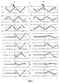
- the current of said phase I A ideally becomes zero downstream of the fault 7 and sees its amplitude increase upstream; however, if the earth fault 7 is very strong, the current variations induced by the fault 7 are very small, up to 20 to 40 times less than the load current, and can be masked by the capacitive currents. As illustrated in figure 2 , a current sensor 12A on the faulty conductor 5A then provides a signal representative of the current I A which does not mark a clear break at the level of the fault 7, because the fault current is low and is hardly noticeable.
- the invention shows that it is possible to overcome this problem of scale by subtracting the load current measured before defect of the fault current I A : as illustrated in FIG. figure 2 , a clear break in the signal provided by the sensor 12A becomes visible. Moreover, the variation of current ⁇ I A in the faulty phase differs according to whether the device according to the invention is disposed upstream 10 i + 1 or downstream 10 i of said sensor 12.
- the correlation coefficients between the different curves are used to determine whether the fault 7 is located upstream or downstream of the sensors 12 supplying signals representative of the currents of the line 5.
- the resemblance between the variation of the homopolar current I 0 and that of the current I A of the faulty phase is important, in contrast to the weak resemblance between the variation of the homopolar current I 0 and that of the currents I B , I C of the other phases; thus, the correlation coefficients normalized with that of the homopolar current I 0 should be, in absolute value, close to unity for phase A and low, for example close to ⁇ 0.1, for the other phases.
- the normalized linear correlation coefficient used in the process according to the invention is preferably obtained by the Bravais-Pearson formula and signed: in fact, the sensors 12 provide an alternating current signal flowing in each of the phases 5A , 5B , C it is preferred to sample so as to obtain a defined number of discrete values representative of the current.
- the number N of values provided by the sampling is adapted to the acquisition duration T acq to optimize the reproducibility and reliability of the results of the Bravais-Pearson formula, that is to say preferably more than 30 values in the case of an acquisition duration T acq equal to a period of the network, with for example a sampling frequency of the order of 1.5 kHz for a 4-phase network at 50 Hz.
- the calculation of the respective variations of the phase currents and of the homopolar current ⁇ I is carried out point by point, with, for each measured value, the subtraction of the value of the load current before defect at the same instant on the sinusoid of the signal. It is preferred not to use a fixed memory window for the reference currents, although this parameter is conventionally used for, for example, measurement and / or qualimetry functions requiring the subtraction of reference values. In fact, most networks 4 have fluctuations in terms of charge and frequency: the frequency of 50 Hz (or 60 Hz) remains the average value with respect to the actual frequency which is not fixed.
- N-point sampling can lead to measurements shifted by a few microseconds on the sinusoid compared to the reference times taken in a fixed window, especially if it is far from the measurement point, which would generate differences in the calculation of the current variation ⁇ I.
- the reference values representative of the charge current just before the fault are thus stored according to the principle of sliding memory, over a window of a duration at least equivalent to T acq : as long as there is no detected fault, the representative values of the signal measured by the sensors 12 replace the first values stored for the same instant on the sinusoid, in order to preserve the samples immediately prior to the fault, which minimizes the possible offsets caused by a fluctuation of the frequency and / or the load.
- the signals representative of the phase currents are acquired over an acquisition period T acq and then sampled; same time, the zero-sequence current I 0 is calculated for the same period, or it can be measured directly via a dedicated core 12.
- the values are stored in an acquisition period T acq in a suitable memory, said storage being slippery, that is, as long as no fault is detected, the last value measured / acquired replaces the previous one.
- the values stored in the memory I 0_MEM , I A_MEM , I B_MEM , I C_MEM are conserved without being replaced, and the signals representative of the phase currents, preferably filtered as before defect, are acquired over an acquisition period T acq , and then sampled; in parallel, the homopolar current I 0 is calculated for the same duration.
- r A , r B , r C Three normalized linear correlation coefficients are thus obtained r A , r B , r C.
- the coefficients A r are closer to 1 or 0.
- the arithmetic mean ⁇ and the standard -type ⁇ of the distribution of the correlation coefficients are used.
- a mean / standard deviation ( ⁇ , ⁇ ) at high average and low standard deviation corresponds to an upstream fault, unlike an average / deviation pair.
- -type ( ⁇ , ⁇ ) with low average and high standard deviation for example ⁇ ⁇ 0.5 and ⁇ > 0.5
- the correlation coefficient is signed here, unlike the one used in the document FR 2 936 319 : the variations due to the fault current are low and the information provided by the sign can not be ignored.
- the comparison according to relation (2), or any directly derived relation thereto is performed and, depending on the result, the directional interpretation L as to the position of the fault is given, either signaled externally, or transmitted to a relay 9 to cut a circuit breaker 6 upstream, or any other use.
- the method according to the invention can be implemented in a protection relay 9, in a fault indicator with warning system, by implementation in a suitable ground fault direction detection device 10.
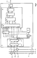
- a device 10 is schematized in figure 4 . It comprises means 14 making it possible to obtain signals representative of the phase currents supplied by suitable sensors 12A, 12B, 12C, for example detection cores, advantageously with filtering by means 16 adapted as an analog filter.
- the filtered I Af , I Bf , I Cf , signals are further conditionned by sampling and the means for obtaining the representative signals 14 comprise a sampling module 18, advantageously operating at more than 1 , 5 kHz, thus providing filtered sampled signals to be processed I Af *, I Bf *, I Cf *.
- the device 10 further comprises means 14 'for obtaining a signal representative of the homopolar current I 0 .
- These means can be coupled directly to a toroid 12 for detecting the current concerned surrounding the line 5 (dashed lines); alternatively, the means 14 'relating to the value of the homopolar current I 0 determine said current by processing the signals relating to the currents of phase I A , I B , I C (not illustrated), advantageously filtered I Af , I Bf , I Cf (not shown), possibly sampled I Af *, I Bf *, I Cf * (solid lines).
- the device 10 further comprises storage means 20 adapted to store in sliding memory on a window of predetermined duration the previous values of the filtered sampled signals of a current of phase I Af *, I Bf *, I Cf * and signal representative of a homopolar current I 0 ; the signals thus stored are stored in the form of reference values I A_MEM , I B_MEM , I C_MEM , I 0_MEM .
- the signals representative of the filtered sampled phase currents I Af *, I Bf *, I Cf * are transmitted to a module processing circuit 30 which comprises a fourth input for the signal representative of the zero sequence current I 0 , four other inputs for the values stored in the storage means 20, and which is activated according to the detection D of a ground fault 10.
- the processing module 30 is connected to any fault detection device, preferably here a module for comparing the zero sequence current I 0 with a detection threshold S d : if the threshold is exceeded, then a fault D is detected and the processing module 30 is activated.
- the processing module 30 successively comprises a computing device 32 for the respective variations of the input signals I Af *, I Bf *, I Cf *, I 0 , with respect to the stored input signals I A_MEM , I B_MEM , I C_MEM , I 0_MEM , a device 34 for calculating normalized correlation coefficients r from the four input signals ⁇ I Af *, ⁇ I Bf *, ⁇ I Cf *, ⁇ I 0 , a computing device 36 of the arithmetic mean ⁇ and of the standard deviation ⁇ of the three data entries r A , r B , r C , a comparison device 38 with two inputs ( ⁇ , ⁇ ) and which is connected to interpretation means 40 whose output is a signal L directional earth fault detection downstream or upstream of the sensors 12 according to the result of the interpretation.
- These means provide at the output the variations of the sampled filtered signals of the phase currents ⁇ I Af *, ⁇ I Bf *, ⁇ I Cf * and the variation of the signal representative of the homopolar current ⁇ I 0 .
- the means for calculating standardized correlated coefficients signed 34 preferably use the Bravais-Pearson formula (1) and are associated with delay means to ensure that the variations of the sampled filtered signals of the phase currents ⁇ I Af * , ⁇ I Bf *, ⁇ I Cf * and the variation of the signal representative of the homopolar current ⁇ I 0 have been acquired over a sufficient period T acq , for example a period of the network 1, or more.
- the comparison means 38 supplying the value to the interpretation module 40 may use different functions.
- the comparison means 38 can include a graphical comparison by two entered values with respect to a half-plane delimited by the half-lines of equation (3); the means 38 can determine the difference between nine eighths of the square of the standard deviation and the square of the average, to compare it to zero; any other option is possible.
- the device 10 of the figure 4 may advantageously be associated with a protection relay 9 for electrical networks, or with a fault-passing indicator for underground medium voltage lines connected in network 1, the output of the interpretation module triggering the breaking of a circuit breaker 6 , lighting a warning light or any other means of security and / or warning.
- a method and a device for directionally detecting a ground fault 7 of a line 5 of a multiphase network 1 have been produced without voltage measurement, which lightens the devices as much as their implementation, for detecting and locating sensitive earth faults on a charged network.
- the embodiment is particularly suitable for the directional detection of a sensitive earth fault, especially when the amplitude of the fault current is less than 10% of the load current, it applies of course in the other cases in place of the process described in FR 2 936 319 although more cumbersome to implement.
- the invention has been described with reference to a three-phase distribution network in which the neutral is grounded by compensated impedance, it is not limited thereto: other types of multiphase networks may be concerned by the invention; in particular, any neutral scheme is appropriate.
- the method according to the invention can use the variation of said current I 0 with respect to its value determined over a prior period: this variant s is particularly interesting in the case of networks having a slight imbalance between phases, whose homopolar current I 0 is therefore non-zero in the off-fault situation.
- the various circuits, modules and functions presented in the context of the preferred embodiment of the invention can be made of analog components, digital or in a programmable form operating with microcontrollers or microprocessors, and the representative signals described may have forms of electrical or electronic signals, data values or information in memories or registers, optical signals viewable in particular on lights or screens, or mechanical signals acting with actuators.
- the current sensors may be different from the described transformers, such as Hall effect sensors or magnetoresistors.
Landscapes
- Physics & Mathematics (AREA)
- Electromagnetism (AREA)
- Engineering & Computer Science (AREA)
- Mathematical Physics (AREA)
- Theoretical Computer Science (AREA)
- General Physics & Mathematics (AREA)
- Emergency Protection Circuit Devices (AREA)
- Testing Of Short-Circuits, Discontinuities, Leakage, Or Incorrect Line Connections (AREA)
- Locating Faults (AREA)
Claims (15)
- Vorrichtung (10) zur Richtungserkennung eines Erdschlusses (7) in einem Mehrphasennetz, die Folgendes aufweist:- erste Mittel (14) zum Empfangen von Signalen, die für den Strom (IA, IB, IC) von jeder der Phasen charakteristisch sind;- zweite Mittel (14') zum Empfangen eines Signals, das für den Nullstrom (I0) sämtlicher Phasen charakteristisch ist;- Mittel (30) zur Verarbeitung der Signale, die für Strom charakteristisch sind, die Mittel (34) zur Berechnung normalisierter Korrelationskoeffizienten (rA, rB, rC) und Mittel (36) zur Berechnung des Mittels (µ) und der Standardabweichung (σ) zwischen den berechneten Korrelationskoeffizienten aufweisen;- Mittel zur Aktivierung der Verarbeitungsmittel (30) in Abhängigkeit von einem Signal (D) der Ermittlung des Auftretens eines Erdschlusses in dem Netz (1);- Mittel zur Interpretation der Ergebnisse der Verarbeitung der Signale, die Mittel zum Vergleich des Mittels (µ) und der Standardabweichung (σ) aufweist, um zu bestimmen, ob der Erdschluss der Vorrichtung (10) vor- oder nachgeschaltet liegt;dadurch gekennzeichnet, dass die Vorrichtung (10) ferner Mittel (20) zur Speicherung von Signalwerten, die für den Nullstrom und jede der Phasen (I0_MEM, IA_MEM, IB_MEM, IC_MEM) charakteristisch sind, während einer Speicherungsdauer (Tacq) vor dem Signal (D) der Ermittlung des Auftretens eines Erdschlusses (7) aufweist, und die Mittel zur Verarbeitung der Signale (30) Mittel zur Bestimmung der Veränderung des Signals, das für den Nullstrom und für jede der Phasen (ΔI0, ΔIA, ΔIB, ΔIC) charakteristisch ist, in Bezug zu den gespeicherten Werten (I0_MEM, IA_MEM, IB_MEM, IC_MEM) während einer vorbestimmten Dauer, die kleiner oder gleich der Speicherungsdauer ist, aufweisen, wobei die Mittel zur Berechnung der normalisierten Korrelationskoeffizienten (34) angepasst sind, um den Korrelationskoeffizienten (rA, rB, rC) zwischen der Veränderung des Signals, das für den Nullstrom (ΔI0) charakteristisch ist, und der Veränderung von jedem der Signale zu berechnen, die für den Phasenstrom (ΔIA, ΔIB, ΔIC) charakteristisch sind.
- Vorrichtung zur Richtungserkennung (10) nach Anspruch 1, wobei die Speicherungsdauer einer ganzen Zahl von Perioden des Netzes (1) entspricht und die bestimmte Dauer gleich der Speicherungsdauer (Tacq) ist.
- Erkennungsvorrichtung nach einem der Ansprüche 1 oder 2, wobei die Speicherungsmittel (20) angepasst sind, um die Werte über einen gleitenden Zeitraum zu speichern und Mittel zur Deaktivierung in Abhängigkeit von einem Signal (D) der Erkennung des Auftretens eines Erdschlusses in dem Netz (1) aufweisen.
- Richtungserkennungsvorrichtung (10) nach einem der Ansprüche 1 bis 3, die ferner Mittel (18) zur Erkennung des Auftretens eines Erdschlusses in dem Netz aufweisen, die mit den Mitteln zur Aktivierung der Mittel zur Verarbeitung der Signale (30) und mit den Speicherungsmitteln (20) verbunden sind, die einen Komparator des Signals, das für den Nullstrom (l0) charakteristisch ist, mit einer Erkennungsschwelle (S0) aufweisen.
- Richtungserkennungsvorrichtung (10) nach einem der Ansprüche 1 bis 4, wobei die ersten Mittel (14) zum Empfang von Signalen, die für die Ströme von jeder Phase (IA, IB, IC) charakteristisch sind, Abtastungsmittel (18) aufweisen, die angepasst sind, um eine genügende Anzahl von Werten während der vorbestimmten Dauer und der Speicherungsdauer (Tacq) zu liefern.
- Erdschlussanzeiger, der Stromsensoren (12A, 12B, 12C) aufweist, die auf jedem Phasenleiter (5A, 5B, 5C) eines zu überwachenden Stromnetzes (1) angeordnet sind, und eine Vorrichtung zur Richtungserkennung eines Erdschlusses (10) nach einem der Ansprüche 1 bis 5 aufweist, die mit den Stromsensoren (12A, 12B, 12C) verbunden ist, um Signale zu empfangen, die für den Phasenstrom (IA, IB, IC) charakteristisch sind.
- Erdschluss-Schutzrelais (9), das mindestens einen Erdschlussanzeiger nach Anspruch 6 und Mittel zur Betätigung einer Abschaltvorrichtung (6) in Abhängigkeit von den Ergebnissen der Interpretationsmittel (40) der Richtungserkennungsvorrichtung (10) des Anzeigers aufweist.
- Verfahren zur Richtungserkennung (D, L) eines Erdschlusses (7) in einem Mehrphasennetz (1), wobei die Signale, die für den Nullstrom (I0_MEM) und jeden der Phasenströme (IA_MEM, IB_MEM, IC_MEM) charakteristisch sind, während einer Dauer (Tacq) von mindestens einer Netzperiode gespeichert werden, das die Auslösung der Richtungserkennung (L) des Erdschlusses (10) infolge des Erhalts eines Signals (D), das das Vorhandensein des Erdschlusses (10) angibt, aufweist, wobei die Richtungserkennung die folgenden aufeinanderfolgenden Schritte aufweist:- Erhalt von Signalen, die für jeden der Phasenströme (IA, IB, IC) über eine vorbestimmte Dauer (Tacq) charakteristisch sind, die kleiner oder gleich der Speicherungsdauer ist;- Erhalt eines Signals, das für den Nullstrom (l0) charakteristisch ist, der in dem Netz während der gleichen vorbestimmten Dauer (Tacq) fließt;- Verarbeitung von Signalen, die für die Phasen- und Erdschlussströme (I0, IA, IB, IC) charakteristisch sind;- Interpretation der Ergebnisse der Verarbeitung der Signale, um anzugeben, ob der erkannte Erdschluss (D) sich dem Ort, an dem die Signale erhalten wurden, die für die Phasenströme (IA, IB, IC) charakteristisch sind, vor- oder nachgeschaltet befindet;dadurch gekennzeichnet, dass der Schritt der Verarbeitung der Signale Folgendes aufweist:- die Berechnung der Veränderung des Nullstroms (I0) von jedem der Phasenströme (IA, IB, IC) über die vorbestimmte Dauer (Tacq) in Bezug zu den gespeicherten Werten (I0_MEM, IA_MEM, IB_MEM, IC_MEM);- die Berechnung der normalisierten Korrelationskoeffizienten (rA, rB, rC) zwischen den Schwankungen der Signale des Nullstroms (ΔI0) und von jedem der Phasenströme (ΔIA, ΔIB, ΔIC) über die vorbestimmte Dauer (Tacq);- die Berechnung des arithmetischen Mittels (µ) und der Standardabweichung (σ) der Korrelationskoeffizienten (rA, rB, rC);- wobei die Interpretation durch einen Vergleich unter Verwendung des Mittels (µ) und der Standardabweichung (σ) ausgeführt wird.
- Verfahren zur Richtungserkennung nach Anspruch 8, wobei die Speicherung der charakteristischen Werte (I0_MEM, IA_MEM, IB_MEM, IC_MEM) auf gleitende Weise erhalten wird, solange das Signal, das das Vorhandensein des Erdschlusses (D) anzeigt, nicht erhalten wird.
- Verfahren zur Richtungserkennung nach Anspruch 8 oder 9, wobei das Signal (D), das das Vorhandensein eines Erdschlusses (7) anzeigt, durch den Empfang eines Signals, das für den Nullstrom (l0) charakteristisch ist, der in dem Netz (1) fließt, und das Ergebnis eines Vergleichs des Nullstromsignals (I0) mit einer Erdschluss-Erkennungsschwelle (S0) erhalten wird.
- Verfahren zur Richtungserkennung nach einem der Ansprüche 8 bis 10, wobei der Interpretationsschritt den Vergleich der Differenz zwischen dem Quadrat des Dreifachen der Standardabweichung (σ) und dem Achtfachen des Quadrates des Mittels (µ) mit Null aufweist.
- Verfahren zur Richtungserkennung nach einem der Ansprüche 8 bis 10, wobei der Schritt der Interpretation den grafischen Vergleich des Mittels (µ) und der Standardabweichung (σ) mit zwei Halbgeraden der Gleichung

- Verfahren zur Richtungserkennung nach einem der Ansprüche 8 bis 12, wobei der Schritt der Lieferung der Signale, die für die Phasenströme (IA, IB, IC) charakteristisch sind, eine Abtastung des Stroms mit einer Frequenz von über 1,5 kHz aufweist.
- Verfahren zur Richtungserkennung nach einem der Ansprüche 8 bis 13, wobei die Berechnung von normalisierten Korrelationskoeffizienten (rA, rB, rC) gemäß der Bravais-Pearson-Formel ausgeführt wird.
- Verfahren zum Schutz einer Stromleitung (5) beim Auftreten eines Erdschlusses (7), das die Betätigung einer Abschaltvorrichtung (6) der Leitung (5) aufweist, wenn ein Erdschluss (7) durch ein Verfahren nach einem der Ansprüche 8 bis 14 der Abschaltvorrichtung (6) nachgelagert erkannt wurde.
Applications Claiming Priority (1)
| Application Number | Priority Date | Filing Date | Title |
|---|---|---|---|
| FR1257023A FR2993670B1 (fr) | 2012-07-20 | 2012-07-20 | Detection directionnelle de defaut terre sensible moyenne tension par correlation lineaire |
Publications (2)
| Publication Number | Publication Date |
|---|---|
| EP2687860A1 EP2687860A1 (de) | 2014-01-22 |
| EP2687860B1 true EP2687860B1 (de) | 2016-03-23 |
Family
ID=47191891
Family Applications (1)
| Application Number | Title | Priority Date | Filing Date |
|---|---|---|---|
| EP13172415.5A Active EP2687860B1 (de) | 2012-07-20 | 2013-06-18 | Richtungs-Erkennung eines empfindlichen Mittelspannungs-Erdschlusses durch lineare Korrelation |
Country Status (5)
| Country | Link |
|---|---|
| EP (1) | EP2687860B1 (de) |
| CN (1) | CN103576045B (de) |
| ES (1) | ES2569080T3 (de) |
| FR (1) | FR2993670B1 (de) |
| RU (1) | RU2631025C2 (de) |
Families Citing this family (16)
| Publication number | Priority date | Publication date | Assignee | Title |
|---|---|---|---|---|
| FR3023444B1 (fr) | 2014-07-02 | 2018-02-16 | Schneider Electric Industries Sas | Module d'alimentation pour equipement modulaire de tele-conduite et equipement le comprenant |
| FR3023429A1 (fr) | 2014-07-02 | 2016-01-08 | Schneider Electric Ind Sas | Equipement modulaire de tele-conduite |
| ES2537131B2 (es) * | 2014-12-23 | 2016-10-07 | Universidad Politécnica de Madrid | Método y sistema direccional de detección de defectos a tierra en redes de corriente continua de cables aislados |
| CN105807174B (zh) * | 2014-12-30 | 2019-02-15 | 施耐德电器工业公司 | 输配电系统保护中的电流互感器断线检测方法 |
| US9829519B2 (en) * | 2015-05-27 | 2017-11-28 | Eaton Corporation | Method and apparatus to commission voltage sensors and branch circuit current sensors for branch circuit monitoring systems |
| US9897647B2 (en) * | 2015-05-27 | 2018-02-20 | Eaton Corporation | Method and apparatus to commission voltage sensors and branch circuit current sensors for branch circuit monitoring systems |
| FI126892B (fi) * | 2016-05-23 | 2017-07-31 | Emtele Oy | Vikavirtaindikaattori |
| WO2018129340A1 (en) * | 2017-01-06 | 2018-07-12 | Liebert Corporation | System and method of identifying path of residual current flow through an intelligent power strip |
| CN112119556B (zh) * | 2018-05-18 | 2023-01-24 | Abb瑞士股份有限公司 | 用于在接地故障保护中使用的方法和设备 |
| ES2911035T3 (es) | 2018-05-18 | 2022-05-17 | Abb Schweiz Ag | Método y aparato para su uso en la protección contra fallos de toma de tierra |
| CN109188177B (zh) * | 2018-10-01 | 2023-12-19 | 江苏国传电气有限公司 | 一种大功率npc三电平逆变器短路电流在线检测系统 |
| CN110927516B (zh) * | 2019-11-14 | 2022-01-21 | 长沙理工大学 | 基于接地变压器分接抽头接地的配电网单相接地故障辨识方法及系统 |
| CN112415327B (zh) * | 2020-10-22 | 2022-04-15 | 中国矿业大学 | 基于接地线电流方向差异的电缆配电网故障区段辨识方法 |
| CN113791310A (zh) * | 2021-09-17 | 2021-12-14 | 威胜电气有限公司 | 一种配电网故障协同处理装置 |
| CN117706281B (zh) * | 2024-02-05 | 2024-06-07 | 昆明理工大学 | 基于相不对称的配电网的故障选线方法、系统及存储介质 |
| CN119001332A (zh) * | 2024-09-10 | 2024-11-22 | 国网北京市电力公司 | 一种高低压配电网故障检测方法与系统 |
Family Cites Families (13)
| Publication number | Priority date | Publication date | Assignee | Title |
|---|---|---|---|---|
| RU95102709A (ru) * | 1995-02-23 | 1996-11-27 | Дагестанский Политехнический Институт | Способ определения направления замыкания на землю в воздушных распределительных сетях |
| JP3384481B2 (ja) * | 1997-02-24 | 2003-03-10 | 東光電気株式会社 | 高圧配電線の地絡検出装置 |
| US6584417B1 (en) * | 1999-10-22 | 2003-06-24 | Abb Inc. | Method and directional element for fault direction determination in a capacitance-compensated line |
| SI21482A (sl) | 2004-06-01 | 2004-10-31 | Marjan Bezjak | Naprava za odkrivanje in izklop prekinjenega polizoliranega vodnika v električnih vodih srednje napetosti |
| RU2006101433A (ru) * | 2006-01-18 | 2007-07-27 | ООО "Электроавтоматика" (RU) | Способ определения направления замыкания на землю |
| EP2169799B1 (de) * | 2008-09-25 | 2019-09-04 | Schneider Electric Industries SAS | Bestimmung der Richtung eines Erdschluss-Fehlers |
| FR2936319B1 (fr) * | 2008-09-25 | 2010-09-10 | Schneider Electric Ind Sas | Detection directionnelle d'un defaut a la terre par correlation lineaire |
| CN101539607B (zh) * | 2009-04-09 | 2011-10-26 | 北京市天利自动化设备研究所 | 一种小电流接地系统接地选线的方法和装置 |
| CN101858948B (zh) * | 2009-04-10 | 2015-01-28 | 阿海珐输配电英国有限公司 | 用于在三相中压配电系统中进行暂态和间歇性接地故障检测和方向确定的方法和系统 |
| EP2278676A1 (de) * | 2009-07-24 | 2011-01-26 | ABB Technology AG | Fehlerrichtungsanzeigevorrichtung und zugehörige Verfahren |
| FR2963967B1 (fr) * | 2010-08-20 | 2012-08-17 | Schneider Electric Ind Sas | Detection directionnelle d'un defaut a la terre avec un seul capteur |
| FR2976363B1 (fr) | 2011-06-07 | 2013-05-24 | Schneider Electric Ind Sas | Detection directionnelle de defaut terre resistant et de rupture de conducteur moyenne tension |
| CN102435896B (zh) * | 2011-09-07 | 2014-01-15 | 中国人民解放军海军工程大学 | 船舶中压电力系统中间歇性接地故障的快速识别方法 |
-
2012
- 2012-07-20 FR FR1257023A patent/FR2993670B1/fr not_active Expired - Fee Related
-
2013
- 2013-06-18 ES ES13172415.5T patent/ES2569080T3/es active Active
- 2013-06-18 EP EP13172415.5A patent/EP2687860B1/de active Active
- 2013-07-19 CN CN201310305593.8A patent/CN103576045B/zh active Active
- 2013-07-19 RU RU2013133963A patent/RU2631025C2/ru active
Also Published As
| Publication number | Publication date |
|---|---|
| CN103576045B (zh) | 2017-06-23 |
| FR2993670B1 (fr) | 2014-07-11 |
| EP2687860A1 (de) | 2014-01-22 |
| RU2013133963A (ru) | 2015-01-27 |
| FR2993670A1 (fr) | 2014-01-24 |
| RU2631025C2 (ru) | 2017-09-15 |
| ES2569080T3 (es) | 2016-05-06 |
| CN103576045A (zh) | 2014-02-12 |
Similar Documents
| Publication | Publication Date | Title |
|---|---|---|
| EP2687860B1 (de) | Richtungs-Erkennung eines empfindlichen Mittelspannungs-Erdschlusses durch lineare Korrelation | |
| EP2741390B1 (de) | Richtungserkennung einer Störung, insbesondere in einem Netz mit kompensiertem oder isoliertem Nulleiter | |
| EP2169799B1 (de) | Bestimmung der Richtung eines Erdschluss-Fehlers | |
| EP2383856B1 (de) | Identifizierung und richtungserfassung eines defekts in einem dreiphasennetz | |
| EP3814788B1 (de) | System und verfahren zur fehlerlokalisierung in einem mehrphasigen leistungssystem unter verwendung der entwicklung von vorwärts- und rückwärtsspannung | |
| EP2421110B1 (de) | Richtungserkennung eines Erdschlusses mit einem einzigen Sensor | |
| FR2936319A1 (fr) | Detection directionnelle d'un defaut a la terre par correlation lineaire | |
| EP2533060B1 (de) | Richtungserkennung eines widerstandsfähigen Erdschlusses und der Unterbrechung eines Leiters mittlerer Spannung | |
| EP1890165B1 (de) | Verfahren zur Richtungserkennung eines Massefehlers und Vorrichtung zur Umsetzung dieses Verfahrens | |
| EP4232834B1 (de) | Verfahren zur erkennung eines fehlers einer batteriemodulgruppe | |
| EP3106887B1 (de) | Verfahren und vorrichtung zur detektion einer störung in einem stromnetz | |
| EP3583432B1 (de) | Verfahren zur überprüfung der verdrahtung eines zählers | |
| EP3001524A1 (de) | Richtungserfassung des masseschlusses in einem stromverteilungsnetz | |
| FR2936378A1 (fr) | Detection directionnelle d'un defaut a la terre a faible echantillonnage | |
| EP4300112B1 (de) | Neutralverlustdetektion | |
| EP0537066B1 (de) | Verfahren zur selektiven Detektion von Widerstandsdefekten in Stromverteilungsnetzwerken | |
| EP2910958A1 (de) | Störungserkennung, insbesondere einer vorübergehenden Störung, in einem Stromnetz | |
| EP3879288B1 (de) | Verfahren zum testen des abschaltens des kapazitiven stroms eines leistungsschalters | |
| FR2999295A1 (fr) | Detection directionnelle d'un defaut dans un reseau a neutre isole | |
| FR2999294A1 (fr) | Detection directionnelle d'un defaut, notamment dans un reseau a neutre compense | |
| EP3798648B1 (de) | Verfahren zur bestimmung der position einer fehlervorstufe in einem in betrieb befindlichen hochspannungskabel | |
| EP1083644B1 (de) | Lichtbogenstromsensitiver Erdfehlerschutz, Auslöser und Schutzschalter mit einer solchen Vorrichtung | |
| EP1290456A1 (de) | Verfahren zur detektion von widerstandsbehafteten fehlern | |
| FR2756051A1 (fr) | Dispositif et procede d'analyse de defauts sur les reseaux de distribution electrique | |
| FR2764071A1 (fr) | Procede d'identification de defauts monophases et dispositif pour la mise en oeuvre d'un tel procede |
Legal Events
| Date | Code | Title | Description |
|---|---|---|---|
| PUAI | Public reference made under article 153(3) epc to a published international application that has entered the european phase |
Free format text: ORIGINAL CODE: 0009012 |
|
| AK | Designated contracting states |
Kind code of ref document: A1 Designated state(s): AL AT BE BG CH CY CZ DE DK EE ES FI FR GB GR HR HU IE IS IT LI LT LU LV MC MK MT NL NO PL PT RO RS SE SI SK SM TR |
|
| AX | Request for extension of the european patent |
Extension state: BA ME |
|
| 17P | Request for examination filed |
Effective date: 20140204 |
|
| RBV | Designated contracting states (corrected) |
Designated state(s): AL AT BE BG CH CY CZ DE DK EE ES FI FR GB GR HR HU IE IS IT LI LT LU LV MC MK MT NL NO PL PT RO RS SE SI SK SM TR |
|
| GRAP | Despatch of communication of intention to grant a patent |
Free format text: ORIGINAL CODE: EPIDOSNIGR1 |
|
| INTG | Intention to grant announced |
Effective date: 20151204 |
|
| GRAS | Grant fee paid |
Free format text: ORIGINAL CODE: EPIDOSNIGR3 |
|
| GRAA | (expected) grant |
Free format text: ORIGINAL CODE: 0009210 |
|
| AK | Designated contracting states |
Kind code of ref document: B1 Designated state(s): AL AT BE BG CH CY CZ DE DK EE ES FI FR GB GR HR HU IE IS IT LI LT LU LV MC MK MT NL NO PL PT RO RS SE SI SK SM TR |
|
| REG | Reference to a national code |
Ref country code: GB Ref legal event code: FG4D Free format text: NOT ENGLISH |
|
| REG | Reference to a national code |
Ref country code: CH Ref legal event code: EP |
|
| REG | Reference to a national code |
Ref country code: AT Ref legal event code: REF Ref document number: 783679 Country of ref document: AT Kind code of ref document: T Effective date: 20160415 |
|
| REG | Reference to a national code |
Ref country code: IE Ref legal event code: FG4D Free format text: LANGUAGE OF EP DOCUMENT: FRENCH |
|
| REG | Reference to a national code |
Ref country code: DE Ref legal event code: R096 Ref document number: 602013005649 Country of ref document: DE |
|
| REG | Reference to a national code |
Ref country code: ES Ref legal event code: FG2A Ref document number: 2569080 Country of ref document: ES Kind code of ref document: T3 Effective date: 20160506 |
|
| REG | Reference to a national code |
Ref country code: FR Ref legal event code: PLFP Year of fee payment: 4 |
|
| REG | Reference to a national code |
Ref country code: LT Ref legal event code: MG4D |
|
| REG | Reference to a national code |
Ref country code: NL Ref legal event code: MP Effective date: 20160323 |
|
| PG25 | Lapsed in a contracting state [announced via postgrant information from national office to epo] |
Ref country code: NO Free format text: LAPSE BECAUSE OF FAILURE TO SUBMIT A TRANSLATION OF THE DESCRIPTION OR TO PAY THE FEE WITHIN THE PRESCRIBED TIME-LIMIT Effective date: 20160623 Ref country code: GR Free format text: LAPSE BECAUSE OF FAILURE TO SUBMIT A TRANSLATION OF THE DESCRIPTION OR TO PAY THE FEE WITHIN THE PRESCRIBED TIME-LIMIT Effective date: 20160624 Ref country code: HR Free format text: LAPSE BECAUSE OF FAILURE TO SUBMIT A TRANSLATION OF THE DESCRIPTION OR TO PAY THE FEE WITHIN THE PRESCRIBED TIME-LIMIT Effective date: 20160323 Ref country code: FI Free format text: LAPSE BECAUSE OF FAILURE TO SUBMIT A TRANSLATION OF THE DESCRIPTION OR TO PAY THE FEE WITHIN THE PRESCRIBED TIME-LIMIT Effective date: 20160323 |
|
| REG | Reference to a national code |
Ref country code: AT Ref legal event code: MK05 Ref document number: 783679 Country of ref document: AT Kind code of ref document: T Effective date: 20160323 |
|
| PG25 | Lapsed in a contracting state [announced via postgrant information from national office to epo] |
Ref country code: LV Free format text: LAPSE BECAUSE OF FAILURE TO SUBMIT A TRANSLATION OF THE DESCRIPTION OR TO PAY THE FEE WITHIN THE PRESCRIBED TIME-LIMIT Effective date: 20160323 Ref country code: RS Free format text: LAPSE BECAUSE OF FAILURE TO SUBMIT A TRANSLATION OF THE DESCRIPTION OR TO PAY THE FEE WITHIN THE PRESCRIBED TIME-LIMIT Effective date: 20160323 Ref country code: SE Free format text: LAPSE BECAUSE OF FAILURE TO SUBMIT A TRANSLATION OF THE DESCRIPTION OR TO PAY THE FEE WITHIN THE PRESCRIBED TIME-LIMIT Effective date: 20160323 Ref country code: NL Free format text: LAPSE BECAUSE OF FAILURE TO SUBMIT A TRANSLATION OF THE DESCRIPTION OR TO PAY THE FEE WITHIN THE PRESCRIBED TIME-LIMIT Effective date: 20160323 Ref country code: LT Free format text: LAPSE BECAUSE OF FAILURE TO SUBMIT A TRANSLATION OF THE DESCRIPTION OR TO PAY THE FEE WITHIN THE PRESCRIBED TIME-LIMIT Effective date: 20160323 |
|
| PG25 | Lapsed in a contracting state [announced via postgrant information from national office to epo] |
Ref country code: PL Free format text: LAPSE BECAUSE OF FAILURE TO SUBMIT A TRANSLATION OF THE DESCRIPTION OR TO PAY THE FEE WITHIN THE PRESCRIBED TIME-LIMIT Effective date: 20160323 Ref country code: IS Free format text: LAPSE BECAUSE OF FAILURE TO SUBMIT A TRANSLATION OF THE DESCRIPTION OR TO PAY THE FEE WITHIN THE PRESCRIBED TIME-LIMIT Effective date: 20160723 Ref country code: EE Free format text: LAPSE BECAUSE OF FAILURE TO SUBMIT A TRANSLATION OF THE DESCRIPTION OR TO PAY THE FEE WITHIN THE PRESCRIBED TIME-LIMIT Effective date: 20160323 |
|
| PG25 | Lapsed in a contracting state [announced via postgrant information from national office to epo] |
Ref country code: SM Free format text: LAPSE BECAUSE OF FAILURE TO SUBMIT A TRANSLATION OF THE DESCRIPTION OR TO PAY THE FEE WITHIN THE PRESCRIBED TIME-LIMIT Effective date: 20160323 Ref country code: AT Free format text: LAPSE BECAUSE OF FAILURE TO SUBMIT A TRANSLATION OF THE DESCRIPTION OR TO PAY THE FEE WITHIN THE PRESCRIBED TIME-LIMIT Effective date: 20160323 Ref country code: PT Free format text: LAPSE BECAUSE OF FAILURE TO SUBMIT A TRANSLATION OF THE DESCRIPTION OR TO PAY THE FEE WITHIN THE PRESCRIBED TIME-LIMIT Effective date: 20160725 Ref country code: CZ Free format text: LAPSE BECAUSE OF FAILURE TO SUBMIT A TRANSLATION OF THE DESCRIPTION OR TO PAY THE FEE WITHIN THE PRESCRIBED TIME-LIMIT Effective date: 20160323 Ref country code: SK Free format text: LAPSE BECAUSE OF FAILURE TO SUBMIT A TRANSLATION OF THE DESCRIPTION OR TO PAY THE FEE WITHIN THE PRESCRIBED TIME-LIMIT Effective date: 20160323 Ref country code: RO Free format text: LAPSE BECAUSE OF FAILURE TO SUBMIT A TRANSLATION OF THE DESCRIPTION OR TO PAY THE FEE WITHIN THE PRESCRIBED TIME-LIMIT Effective date: 20160323 |
|
| PG25 | Lapsed in a contracting state [announced via postgrant information from national office to epo] |
Ref country code: BE Free format text: LAPSE BECAUSE OF NON-PAYMENT OF DUE FEES Effective date: 20160630 |
|
| REG | Reference to a national code |
Ref country code: DE Ref legal event code: R097 Ref document number: 602013005649 Country of ref document: DE |
|
| PLBE | No opposition filed within time limit |
Free format text: ORIGINAL CODE: 0009261 |
|
| STAA | Information on the status of an ep patent application or granted ep patent |
Free format text: STATUS: NO OPPOSITION FILED WITHIN TIME LIMIT |
|
| PG25 | Lapsed in a contracting state [announced via postgrant information from national office to epo] |
Ref country code: MC Free format text: LAPSE BECAUSE OF FAILURE TO SUBMIT A TRANSLATION OF THE DESCRIPTION OR TO PAY THE FEE WITHIN THE PRESCRIBED TIME-LIMIT Effective date: 20160323 Ref country code: DK Free format text: LAPSE BECAUSE OF FAILURE TO SUBMIT A TRANSLATION OF THE DESCRIPTION OR TO PAY THE FEE WITHIN THE PRESCRIBED TIME-LIMIT Effective date: 20160323 |
|
| REG | Reference to a national code |
Ref country code: CH Ref legal event code: PL |
|
| PG25 | Lapsed in a contracting state [announced via postgrant information from national office to epo] |
Ref country code: BG Free format text: LAPSE BECAUSE OF FAILURE TO SUBMIT A TRANSLATION OF THE DESCRIPTION OR TO PAY THE FEE WITHIN THE PRESCRIBED TIME-LIMIT Effective date: 20160623 |
|
| 26N | No opposition filed |
Effective date: 20170102 |
|
| REG | Reference to a national code |
Ref country code: IE Ref legal event code: MM4A |
|
| PG25 | Lapsed in a contracting state [announced via postgrant information from national office to epo] |
Ref country code: CH Free format text: LAPSE BECAUSE OF NON-PAYMENT OF DUE FEES Effective date: 20160630 Ref country code: LI Free format text: LAPSE BECAUSE OF NON-PAYMENT OF DUE FEES Effective date: 20160630 |
|
| PG25 | Lapsed in a contracting state [announced via postgrant information from national office to epo] |
Ref country code: IE Free format text: LAPSE BECAUSE OF NON-PAYMENT OF DUE FEES Effective date: 20160618 Ref country code: SI Free format text: LAPSE BECAUSE OF FAILURE TO SUBMIT A TRANSLATION OF THE DESCRIPTION OR TO PAY THE FEE WITHIN THE PRESCRIBED TIME-LIMIT Effective date: 20160323 |
|
| REG | Reference to a national code |
Ref country code: FR Ref legal event code: PLFP Year of fee payment: 5 |
|
| PG25 | Lapsed in a contracting state [announced via postgrant information from national office to epo] |
Ref country code: HU Free format text: LAPSE BECAUSE OF FAILURE TO SUBMIT A TRANSLATION OF THE DESCRIPTION OR TO PAY THE FEE WITHIN THE PRESCRIBED TIME-LIMIT; INVALID AB INITIO Effective date: 20130618 Ref country code: CY Free format text: LAPSE BECAUSE OF FAILURE TO SUBMIT A TRANSLATION OF THE DESCRIPTION OR TO PAY THE FEE WITHIN THE PRESCRIBED TIME-LIMIT Effective date: 20160323 |
|
| REG | Reference to a national code |
Ref country code: FR Ref legal event code: PLFP Year of fee payment: 6 |
|
| PG25 | Lapsed in a contracting state [announced via postgrant information from national office to epo] |
Ref country code: MT Free format text: LAPSE BECAUSE OF FAILURE TO SUBMIT A TRANSLATION OF THE DESCRIPTION OR TO PAY THE FEE WITHIN THE PRESCRIBED TIME-LIMIT Effective date: 20160323 Ref country code: TR Free format text: LAPSE BECAUSE OF FAILURE TO SUBMIT A TRANSLATION OF THE DESCRIPTION OR TO PAY THE FEE WITHIN THE PRESCRIBED TIME-LIMIT Effective date: 20160323 Ref country code: LU Free format text: LAPSE BECAUSE OF NON-PAYMENT OF DUE FEES Effective date: 20160618 Ref country code: MK Free format text: LAPSE BECAUSE OF FAILURE TO SUBMIT A TRANSLATION OF THE DESCRIPTION OR TO PAY THE FEE WITHIN THE PRESCRIBED TIME-LIMIT Effective date: 20160323 |
|
| PG25 | Lapsed in a contracting state [announced via postgrant information from national office to epo] |
Ref country code: AL Free format text: LAPSE BECAUSE OF FAILURE TO SUBMIT A TRANSLATION OF THE DESCRIPTION OR TO PAY THE FEE WITHIN THE PRESCRIBED TIME-LIMIT Effective date: 20160323 |
|
| PGFP | Annual fee paid to national office [announced via postgrant information from national office to epo] |
Ref country code: DE Payment date: 20250626 Year of fee payment: 13 |
|
| PGFP | Annual fee paid to national office [announced via postgrant information from national office to epo] |
Ref country code: GB Payment date: 20250617 Year of fee payment: 13 |
|
| PGFP | Annual fee paid to national office [announced via postgrant information from national office to epo] |
Ref country code: FR Payment date: 20250624 Year of fee payment: 13 |
|
| PGFP | Annual fee paid to national office [announced via postgrant information from national office to epo] |
Ref country code: ES Payment date: 20250710 Year of fee payment: 13 |
|
| PGFP | Annual fee paid to national office [announced via postgrant information from national office to epo] |
Ref country code: IT Payment date: 20250623 Year of fee payment: 13 |