EP2687867A2 - Affichage fusionné de géoradar pour antennes multiples - Google Patents
Affichage fusionné de géoradar pour antennes multiples Download PDFInfo
- Publication number
- EP2687867A2 EP2687867A2 EP13169794.8A EP13169794A EP2687867A2 EP 2687867 A2 EP2687867 A2 EP 2687867A2 EP 13169794 A EP13169794 A EP 13169794A EP 2687867 A2 EP2687867 A2 EP 2687867A2
- Authority
- EP
- European Patent Office
- Prior art keywords
- antenna
- output
- depth
- visual output
- range
- Prior art date
- Legal status (The legal status is an assumption and is not a legal conclusion. Google has not performed a legal analysis and makes no representation as to the accuracy of the status listed.)
- Granted
Links
Images





Classifications
-
- G—PHYSICS
- G01—MEASURING; TESTING
- G01S—RADIO DIRECTION-FINDING; RADIO NAVIGATION; DETERMINING DISTANCE OR VELOCITY BY USE OF RADIO WAVES; LOCATING OR PRESENCE-DETECTING BY USE OF THE REFLECTION OR RERADIATION OF RADIO WAVES; ANALOGOUS ARRANGEMENTS USING OTHER WAVES
- G01S7/00—Details of systems according to groups G01S13/00, G01S15/00, G01S17/00
- G01S7/02—Details of systems according to groups G01S13/00, G01S15/00, G01S17/00 of systems according to group G01S13/00
- G01S7/04—Display arrangements
- G01S7/06—Cathode-ray tube displays or other two dimensional or three-dimensional displays
- G01S7/20—Stereoscopic displays; Three-dimensional [3D] displays; Pseudo-3D displays
-
- G—PHYSICS
- G01—MEASURING; TESTING
- G01S—RADIO DIRECTION-FINDING; RADIO NAVIGATION; DETERMINING DISTANCE OR VELOCITY BY USE OF RADIO WAVES; LOCATING OR PRESENCE-DETECTING BY USE OF THE REFLECTION OR RERADIATION OF RADIO WAVES; ANALOGOUS ARRANGEMENTS USING OTHER WAVES
- G01S7/00—Details of systems according to groups G01S13/00, G01S15/00, G01S17/00
- G01S7/02—Details of systems according to groups G01S13/00, G01S15/00, G01S17/00 of systems according to group G01S13/00
- G01S7/04—Display arrangements
-
- G—PHYSICS
- G01—MEASURING; TESTING
- G01S—RADIO DIRECTION-FINDING; RADIO NAVIGATION; DETERMINING DISTANCE OR VELOCITY BY USE OF RADIO WAVES; LOCATING OR PRESENCE-DETECTING BY USE OF THE REFLECTION OR RERADIATION OF RADIO WAVES; ANALOGOUS ARRANGEMENTS USING OTHER WAVES
- G01S13/00—Systems using the reflection or reradiation of radio waves, e.g. radar systems; Analogous systems using reflection or reradiation of waves whose nature or wavelength is irrelevant or unspecified
- G01S13/88—Radar or analogous systems specially adapted for specific applications
- G01S13/885—Radar or analogous systems specially adapted for specific applications for ground probing
-
- G—PHYSICS
- G01—MEASURING; TESTING
- G01S—RADIO DIRECTION-FINDING; RADIO NAVIGATION; DETERMINING DISTANCE OR VELOCITY BY USE OF RADIO WAVES; LOCATING OR PRESENCE-DETECTING BY USE OF THE REFLECTION OR RERADIATION OF RADIO WAVES; ANALOGOUS ARRANGEMENTS USING OTHER WAVES
- G01S13/00—Systems using the reflection or reradiation of radio waves, e.g. radar systems; Analogous systems using reflection or reradiation of waves whose nature or wavelength is irrelevant or unspecified
- G01S13/87—Combinations of radar systems, e.g. primary radar and secondary radar
Definitions
- the disclosed technology relates generally to ground-penetrating radar (GPR), and, more specifically, to a technique for displaying GPR data.
- GPR ground-penetrating radar
- GPR ground-penetrating RADAR
- RADAR is "RAdio Detection And Ranging”
- GPR uses radio frequencies and is particularly useful in that it is both non-destructive and non-ionizing. In fact, GPR uses frequencies similar to a cellular phone, but at far lower power levels. Common applications include locating the precise position of rebar within a concrete wall/floor, identifying and locating buried objects underground, assessing the quality and uniformity of an asphalt or concrete highway surface, and detecting deterioration on bridge decks.
- GPR is used, for example, to detect cracks, fissures, or contamination in any one of the chip seal, pavement layers, gravel base, and so forth.
- a resolution of features of the road surface of less than one inch (2.54 cm) is desired.
- Such systems may be mounted on vehicles, travelling over the surface while acquiring measurement data.
- GPR systems are disclosed in more detail in U.S. Patent 5,499,029 to Bashforth, et al. , and U.S. Patent 5,384,715 to Lytton , which are hereby incorporated by reference.
- Ground Penetrating Radar (GPR) antennas are built in different sizes for different uses. Smaller antennas are generally higher in frequency, have higher resolution for displaying finer details and are not able to penetrate as deep as lower frequency antennas. Larger antennas are generally lower in frequency, are able to penetrate deeper, but have a lower resolution, and so are not able to discriminate fine details.
- GPR Ground Penetrating Radar
- a visual output of data from a ground-penetrating radar is displayed on a visual medium.
- the display has a first exhibition of output from a higher frequency range antenna, a second exhibition of output from a lower frequency range antenna (compared to the other antenna; see definition in the "detailed description"), and a transition area between the first and second exhibition having merged data from the higher frequency antenna and the lower frequency antenna.
- the depth range of this transition zone may be varied based on optimal depth range of each antenna, such as manually by a viewer viewing the visual output, which may occur in real-time, that is, while operating the radar and viewing the visual output thereof.
- the transition depth range and/or width of the transition region may be varied as part of post-processing.
- Post-processing for purposes of this disclosure, is defined as a time after all data used to produce the visual output has been collected. Real-time processing is defined as processing as the data is received, but is merged before being displayed on the visual output.
- the depth range of the transition region may be varied automatically, based on a detected amount of disjoined data per unit area in each output of each antenna, and/or based on a determined noise floor, and/or based on closeness of matching of data received from each antenna within a transition range. In this manner, the depth range is re-calculated as the scanning progresses. This may lead to having a non-linear transition region, which may include a different starting depth and/or ending depth of the transition region.
- any number of antennas may be used, each having a different optimal frequency range, with a transition depth range exhibited in the visual output between exhibition from each antenna.
- the display has part of a visual output from each determined best depth range and at least one transition region comprising a transitioned output between two best depth ranges.
- Figure 1 shows sample output graph of data generated by two ground-penetrating radar antennas, in an embodiment of the disclosed technology.
- Figure 2A shows an actual image generated using GPR with a high frequency antenna.
- Figure 2B shows an actual image generated using GPR with a low frequency antenna.
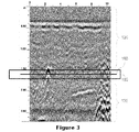
- Figure 3 shows a transition area between two image outputs from two different antennas, in an embodiment of the disclosed technology
- Figure 4A shows which portions of two image outputs are used to form a merged graphical output, in an embodiment of the disclosed technology.
- Figure 4B shows a merged image output, including a transition region, using the graphical outputs shown in Figure 4A , in an embodiment of the disclosed technology.
- Figure 5A shows a clean version of the two image outputs used to form a merged graphical output, of Figure 4A .
- Figure 5B shows a clean version of the merged image output of Figure 4B .
- Figure 6 shows output of a merged image output, of an embodiment of the disclosed technology.
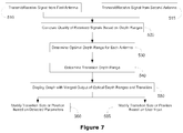
- Figure 7 is a high-level flow chart of steps taken to produce a graphical GPR output in embodiments of the disclosed technology.
- Figure 8 shows a high-level block diagram of a device that may be used to carry out the disclosed technology.
- a visual output of data from a ground-penetrating radar is displayed on a visual medium.
- the display has a first exhibition of output from a higher frequency range antenna, a second exhibition of output from a lower frequency range antenna (compared to the other antenna; see definition in the "detailed description"), and a transition area between the first and second exhibition having merged data from the lower frequency antenna and the higher frequency antenna.
- the depth range of the transition area may be varied based on optimal depth range of each antenna, such as manually by a viewer viewing the visual output, which may occur in real-time, that is, while operating the radar and viewing the visual output thereof.
- the transition depth range and/or width of the transition region may be varied as part of post-processing.
- Figure 1 shows sample output of data generated by two ground-penetrating radar antennas, in an embodiment of the disclosed technology.
- the high frequency output 100 is shown on the left graph
- the low frequency output 130 is shown in the middle graph
- a blended output 160 is shown in the graph on the right.
- the y-axis is measured in depth in meters
- the x-axis is the signal amplitude at each depth location.
- "High” or “higher” frequency and “low” or “lower” frequency are defined relative to each other. That is, when two antennas are used or claimed, it is to be understood that the "high” or “higher” frequency antennas is higher than the "low” or “lower” frequency antennas.
- An antenna used may be capable of measuring over the entire frequency range, however, a "high” or “low” frequency antenna, for purposes of this disclosure, is one that measures best at a higher or lower frequency band compared to another antenna used in a GPR system.
- GPR is often used in the range / band of 300 to 900 Mhz.
- a "higher” frequency antenna would be optimized (defined as producing the most precise resulting measurements, compared to other antennas used in conjunction to produce a graphical output) at the highest of the frequencies, in this example, at 900 Mhz and in the vicinity thereof (such as covering 10%, 25%, or 50% of the band, from the top).
- a "lower” frequency antenna would be optimized (defined, again, as producing the most precise resulting measurements, compared to other antennas used in conjunction to produce a graphical output), at the lowest of the frequencies. In this example, the lower frequency antenna would be optimized (produce a better result) at 300 Mhz and in the vicinity thereof.
- a plurality of antennas may be used to measure in other bands such as between 900 Mhz to 3000 Mhz for concrete, 10 Mhz to 400 Mhz for geological surveys, or 400 to 5000 Mhz in the transportation industry.
- the disclosed technology is limited to impulse-type antennas.
- the higher frequency antenna 100 has the most accurate (defined as optimal or precise) measurements at a range of 0 to about 1.6 meters in depth. Below this depth, the output of the high frequency antenna 100, in this example, is mostly noise.
- the lower frequency antenna 130 has the most accurate measurements at depths below about 1.6 meters.
- a blended graph 160 places the output of data generated from the higher frequency GPR antenna above transition depth point 180, and the output of data generated from the lower frequency GPR antenna below transition depth point 180.
- the transition depth point 180 is a depth defined where a center point of a transitional merger between output of two different antennas is located.
- the transitional merger range of depth, or transition area of the graph may vary in size (range of depth) based on a variety of factors.
- This manipulation of the line 180 may be done in real-time, while collecting GPR data, or after the data has been collected as part of post-processing.
- the transition area and methods of determining same is discussed in greater detail below.
- Figure 2A shows an actual graph generated using GPR with a high frequency antenna.
- Figure 2B shows an actual graph generated using GPR with a low frequency antenna.
- the graph from the high frequency antenna 105 shows much more data at smaller depths than the graph from the low frequency antenna 135.
- the low frequency antenna 135 graph has clearer (more precise) data at lower depths. Again, this is obvious to the naked eye, and as such, a user may indicate a depth for the center of the transition region 180. However, this may also be determined by knowing in advance the parameters of an antenna being used and pre-defining its best ranges.
- the high frequency antenna may be pre-defined, based on known characteristics to be used from 0 m downwards with a lower depth of not less than 1.5 m and not more than 2 m.
- the lower frequency antenna may be programmed between not less than 1.6 m to a depth of infinity.
- the maximum depth of the first antenna and the minimum depth of the second antenna may be averaged, or a preferred transition range may be specified.
- the user may simply select an antenna profile to use, from a pre-populated list of antennas associated with various antennas. Such a pre-populated list may further be modified based on usage - that is, the transition point previously selected by a user. Similarly, this method or combination thereof may be employed when using three or more antennas. Between each exhibition of data received by way of an antenna, is a transition region showing a merger of data from two graph regions, one for each of two antennas.
- a first method involves determining a noise floor for all but the lowest frequency band antenna.
- the noise floor is the measure of the signal created from the sum of all the noise sources and unwanted signals within a measurement system, where noise is defined as any signal other than the one being monitored and the noise floor is the deepest measured point where noise is within an acceptable range to adequately view the desired data. If the dominant noise is generated within the measuring equipment then this is an example of an instrumentation noise floor, as opposed to a physical noise floor.
- the noise floor 190 is shown, and at the minimum noise floor depth of around 260 meters, the visual output is no longer of use. As such, the transition region begins, in an embodiment of the disclosed technology, at or above the minimum noise floor depth.
- Another method of automatically determining where a transition depth is, and further, transition area where data from two graphs is merged together involves detecting an amount of disjoined data per unit area in each output of each antenna. This may be determined by viewing the output from a single antenna, converting the plot of the data to digital data, and determining the number of pixels which are a) not adjacent to another other pixel, and b) adjacent to only one other pixel, and c) determining the density of pixels within a square, rectangle, or circle around a lone pixel or pixel, such as with a diameter or length of 2, 4, 6, 8, 10 or 20 pixels.
- the disjoined data, in a pixel unit area, or density thereof may be compared to the graphical output in the same region from another antenna.
- Figure 3 highlights transition area between two graphical outputs from two different antennas, in an embodiment of the disclosed technology.
- Depth range / graphical output 105 is the same as part of the output shown in Figure 2A
- depth range / graphical output 135 is the same as part of the output shown in Figure 2B . That is, this figure shows the merger of the two graphical outputs, split at around 1.6 m.
- the size of transition area may be pre-defined, such as 2%, 5%, or 10% of the total graph or total size of two antenna depth ranges when using three or more antennas.
- a user may choose to modify the size of the transition region, in real-time or part of post processing.
- an optimal transition range may be determined where differences between output 105 and output 135 vary the least.
- the data outputted in the transition region 185 may then be blended together (defined as varied by software data tools sending commands to a processor to determine which groupings of pixels or lines of pixels are close enough together to move, as little as possible, to join lines and groupings of pixels into a fluid path with one another, and/or deleting or tapering off lines of pixels which would abruptly end when joining to output from another antenna).
- Figure 4A shows which portions of two graphical outputs are used to form a merged graphical output, in an embodiment of the disclosed technology.
- Figure 4B shows a merged graphical output, including a transition region, using the graphical outputs shown in Figure 4A , in an embodiment of the disclosed technology.
- a depth range is deleted as shown in selected region 106 of the output 105.
- a transition region 185 is created in Figure 4B , corresponding to the deleted region of Figure 4A .
- the selected region 106 of output 105 is that which is above and outside the depth range of the noise floor 190, in order to exclude the noise floor and anything beneath this floor in the merged output.
- a continuous graphical output over the regions 106 (the portion of output 105 selected for the merged output) and 136 (the portion of output 135 selected for the merged output), from two antennas, is created producing a result more clear and precise than either antenna could provide alone.
- Another method of determining transition position and range is overlap in measurements between output from two antennas. This, in turn, determines which portions (e.g. 106 and 136) of the outputs are used in the merged display. For example, a statistical sampling or comparison may be taken at regular intervals between two antennas, such as for example every .5 meters, 1 meter, or 2 meters in depth. If the output is exceedingly different (defined as more than 25% different) one may conclude (manually or automatically) that one is measuring at a depth which is optimal for only one antenna. However, if the output is exceedingly similar (defined as more than 90% identical or statistically similar where statistically similar is defined as within 2 pixels of each other, then one may conclude that this is a potentially optimal depth for two antennas. Since the matching is close, or closest, this depth may be used as a center of a transition region, such as region 185 as the merged data will roughly overlap, resulting in a smooth picture.
- this depth may be used as a center of a transition region, such as region 185 as
- Figure 5A shows a clean version of the two graphical outputs used to form a merged graphical output, of Figure 4A .
- Figure 5B shows a clean version of the merged graphical output of Figure 4B .
- Figure 6 shows output of a merged graphical output, of an embodiment of the disclosed technology.
- the two visual outputs of Figure 5A obtained with two different antennas produce output 105 and 135 respectively.
- a new output 200 is formed. This new output 200 is comprised of parts of the output from a first output 105, second output 135, and merged region 185.
- Figure 6 shows output of a merged graphical output, of an embodiment of the disclosed technology.
- the merged output 200 shows the clearest output across all depth regions.
- FIG. 7 is a high-level flow chart of steps taken to produce a graphical GPR output in embodiments of the disclosed technology.
- a signal is transmitted and received from a first antenna, and in 515, likewise from a second antenna.
- Each of the two antennas may have a transmitter and/or a receiver. Of all the antennas used, there must be at least one transmitter and at least one receiver, and at least two combinations of transmitter and receiver so that two different data sets are produced.
- the transmitter and receiver, on a single antenna may be two different electrically coupled physical devices, or may be the same physical device on the antenna. While two antennas are used in Figure 5 , it should be understand that at least two antennas are used, and the method may proceed similarly with three, four, five, or more antennas.
- step 520 the quality of the received signals is compared based on the signal at various depth ranges. As described above, this may be accomplished manually (by viewing the output), but semi-automated mechanisms (such as based on inputted or detected information about each antenna), or by fully automated mechanisms (such as by determining a noise floor and/or determining dis-joined or erroneous pixel density).
- optimal depth ranges for each antenna are determined in step 530, and then a transition depth range is determined in step 540.
- the transition depth range is the starting and ending depth where graphically outputted data is merged (based off of) output from two antennas, one being shown at a shallower depth than the transition depth range, and one being shown at a deeper depth than the transition depth range.
- the transition depth range thus includes output from two different antennas, merged together.
- the number of transition depth ranges is equal to the number of antennas used to produce the graphical output minus one.
- a first antenna may be determined to have an optimal depth range of 0 to 2 meters.
- a second from 2 to 10 meters.
- a third from 10 to 20 meters.
- a transition range between each of these depths be set by any one of, or a combination of, pre-setting or selecting a depth range, making such a determination based on aesthetic overlap of the graphs, optimizing for as much unmerged depth ranges as possible, and/or where noise and artifacts are most prominent for both antennas bordering the transition depth range).
- first transition depth range is 2 meters and a second transition depth range is 10 meters
- output as follows, would be displayed, in step 550: 0 - 1.8 meters first antenna 1.8 - 2.2 meters first transition 2.2 - 9.5 meters second antenna 9.5 - 10.5 meters second transition 10.5 - 20 meters third antenna
- a graphical output is displayed with merged output of optimal depth ranges and transition ranges.
- a user may decide to modify the transition size or position based on detected parameters, such as, based on viewing the output and deciding to adjust same with a slider.
- the transition size or position may be modified based on detected parameters, such as described above, based on determined dis-joined data and so forth.
- the radar data may be acquired by two antennas which are co-located, or by two physically connected antennas which are not co-located (that is, they are located at two different places but combine electrically or through post-processing to arrive at a better received signal for a particular position).
- Multiple antennas may also be moved over a target area, at different times such as sequentially within a short time span, so long as the data received overlaps within an acceptable tolerance level at a particular depth range, so that a transition range for the display may be determined by one of the methods described herein-above.
- Figure 8 shows a high-level block diagram of a device that may be used to carry out the disclosed technology.
- Device 700 comprises a processor 750 that controls the overall operation of the computer by executing the measurement device's program instructions which define such operation.
- the measurement device's program instructions may be stored in a storage device 720 (e.g., magnetic disk, flash disk, database) and loaded into memory 730 when execution of the measurement device's program instructions is desired.
- the measurement device's operation will be defined by the measurement device's program instructions stored in memory 730 and/or storage 720, and the measurement device will be controlled by processor 750 executing the measurement device's program instructions.
- a device 700 also includes one or a plurality of input network interfaces for communicating with other devices via a network (e.g., the internet).
- a device 700 also includes one or more output network interfaces 710 for communicating with other devices.
- Device 700 also includes input/output 740 representing devices which allow for user interaction with the computer 700 (e.g., display, keyboard, mouse, speakers, buttons, etc.).
- input/output 740 representing devices which allow for user interaction with the computer 700 (e.g., display, keyboard, mouse, speakers, buttons, etc.).
- Figure 7 is a high level representation of some of the components of such a measurement device for illustrative purposes. It should also be understood by one skilled in the art that the method and devices depicted in Figures 1 through 5 may be implemented on a device such as is shown in Figure 6 .
Landscapes
- Engineering & Computer Science (AREA)
- Physics & Mathematics (AREA)
- Radar, Positioning & Navigation (AREA)
- Remote Sensing (AREA)
- Computer Networks & Wireless Communication (AREA)
- General Physics & Mathematics (AREA)
- Electromagnetism (AREA)
- Radar Systems Or Details Thereof (AREA)
- Geophysics And Detection Of Objects (AREA)
Applications Claiming Priority (2)
| Application Number | Priority Date | Filing Date | Title |
|---|---|---|---|
| US201261672902P | 2012-07-18 | 2012-07-18 | |
| US13/588,183 US8957809B2 (en) | 2012-07-18 | 2012-08-17 | Merged ground penetrating radar display for multiple antennas |
Publications (3)
| Publication Number | Publication Date |
|---|---|
| EP2687867A2 true EP2687867A2 (fr) | 2014-01-22 |
| EP2687867A3 EP2687867A3 (fr) | 2014-08-13 |
| EP2687867B1 EP2687867B1 (fr) | 2017-07-12 |
Family
ID=48520793
Family Applications (1)
| Application Number | Title | Priority Date | Filing Date |
|---|---|---|---|
| EP13169794.8A Not-in-force EP2687867B1 (fr) | 2012-07-18 | 2013-05-29 | Affichage fusionné de géoradar pour antennes multiples |
Country Status (3)
| Country | Link |
|---|---|
| US (1) | US8957809B2 (fr) |
| EP (1) | EP2687867B1 (fr) |
| CN (1) | CN103576127B (fr) |
Cited By (2)
| Publication number | Priority date | Publication date | Assignee | Title |
|---|---|---|---|---|
| US20140022117A1 (en) * | 2012-07-18 | 2014-01-23 | Geophysical Survey Systems, Inc. | Merged Ground Penetrating Radar Display for Multiple Antennas |
| CN115755193A (zh) * | 2022-10-26 | 2023-03-07 | 广西北投交通养护科技集团有限公司 | 路面结构内部病害识别方法 |
Families Citing this family (7)
| Publication number | Priority date | Publication date | Assignee | Title |
|---|---|---|---|---|
| WO2007027760A2 (fr) | 2005-08-30 | 2007-03-08 | Troxler Electronic Laboratories, Inc. | Procedes, systemes et produits-programmes pour determiner une propriete d'un materiau de construction |
| IL221596A (en) * | 2012-08-23 | 2017-12-31 | Beeri Amir | METHOD AND DEVICE FOR VOLUME VISUALIZATION IN A WIDE RADAR IMAGING SYSTEM |
| US10809372B2 (en) * | 2015-05-11 | 2020-10-20 | Vayyar Imaging Ltd. | System, device and methods for imaging of objects using electromagnetic array |
| CN105117503B (zh) * | 2015-10-14 | 2016-04-06 | 山东工商学院 | 一种探地雷达数据可视化方法 |
| CN105488141B (zh) * | 2015-11-25 | 2018-02-06 | 山东工商学院 | 一种探地雷达数据的可视方法 |
| US10222465B2 (en) * | 2015-12-29 | 2019-03-05 | Geophysical Survey Systems, Inc. | Magnetic field detector and ground-penetrating radar device with merged display |
| ES2984945T3 (es) * | 2017-01-27 | 2024-10-31 | Massachusetts Inst Technology | Método y sistema para la localización de un vehículo utilizando un radar de penetración superficial |
Citations (2)
| Publication number | Priority date | Publication date | Assignee | Title |
|---|---|---|---|---|
| US5384715A (en) | 1993-08-27 | 1995-01-24 | The Texas A&M Univeristy System | System identification and analysis of subsurface radar signals |
| US5499029A (en) | 1992-07-14 | 1996-03-12 | Eg&G Energy Measurements, Inc. | Wide band stepped frequency ground penetrating radar |
Family Cites Families (44)
| Publication number | Priority date | Publication date | Assignee | Title |
|---|---|---|---|---|
| US5325095A (en) | 1992-07-14 | 1994-06-28 | The United States Of America As Represented By The United States Department Of Energy | Stepped frequency ground penetrating radar |
| US5835053A (en) | 1993-06-28 | 1998-11-10 | Road Radar Ltd. | Roadway ground penetrating radar system |
| US5502686A (en) | 1994-08-01 | 1996-03-26 | Western Atlas International | Method and apparatus for imaging a borehole sidewall |
| US5835054A (en) | 1996-03-01 | 1998-11-10 | The Regents Of The University Of California | Ultra wideband ground penetrating radar imaging of heterogeneous solids |
| US6094157A (en) | 1996-09-06 | 2000-07-25 | Underground Imaging, Inc. | Oblique scanning ground penetrating radar |
| US5912639A (en) | 1997-05-23 | 1999-06-15 | Power Spectra, Inc. | Ground penetrating radar with synthesized end-fire array |
| CA2266214C (fr) | 1998-03-20 | 2002-09-17 | Sensors & Software Inc. | Antenne a largeur de bande super-grande pour radar servant au sondage du sol et systemes radar uwb |
| US5952954A (en) | 1998-04-23 | 1999-09-14 | Power Spectra, Inc. | Ground penetrating radar with synthesized end-fire array |
| US6091354A (en) | 1998-04-23 | 2000-07-18 | Power Spectra, Inc. | Ground penetrating radar with synthesized end-fire array |
| CN1239778A (zh) * | 1998-06-18 | 1999-12-29 | 王惠琴 | 电磁波束定向发射勘查技术 |
| US6082466A (en) | 1998-10-28 | 2000-07-04 | Caterpillar Inc. | Rowcrop machine guidance using ground penetrating radar |
| US6501413B2 (en) | 1999-03-22 | 2002-12-31 | Sensors & Software Inc. | Timing and control and data acquisition for a multi transducer ground penetrating radar system |
| US6496137B1 (en) | 1999-09-19 | 2002-12-17 | Mala Geoscience Ab | Ground penetrating radar array and timing circuit |
| US6308787B1 (en) | 1999-09-24 | 2001-10-30 | Vermeer Manufacturing Company | Real-time control system and method for controlling an underground boring machine |
| NL1013661C2 (nl) | 1999-11-24 | 2001-06-14 | Univ Delft Tech | Gronddoordringende radarinrichting en werkwijze voor het detecteren van een object op of onder een grondoppervlak. |
| US6833795B1 (en) | 1999-11-30 | 2004-12-21 | Vermeer Manufacturing Company | Underground utility detection system and method employing ground penetrating radar |
| FR2802303B1 (fr) | 1999-12-14 | 2002-03-08 | Centre Nat Rech Scient | Procede d'obtention d'une imagerie du sous-sol utilisant un radar a penetration de sol |
| AUPQ592600A0 (en) | 2000-02-29 | 2000-03-23 | Cea Technologies Inc. | Ground penetrating radar |
| US6496136B1 (en) | 2000-05-15 | 2002-12-17 | Anthony N. Mucciardi | Ground penetrating radar system for non-invasive inspection of trees for internal decay |
| US6700526B2 (en) | 2000-09-08 | 2004-03-02 | Witten Technologies Inc. | Method and apparatus for identifying buried objects using ground penetrating radar |
| US6603422B2 (en) | 2000-11-17 | 2003-08-05 | James Burton Wright | Ground penetrating radar incorporating a real-time multi-target direction finding capability |
| US6915216B2 (en) | 2002-10-11 | 2005-07-05 | Troxler Electronic Laboratories, Inc. | Measurement device incorporating a locating device and a portable handheld computer device and associated apparatus, system and method |
| US6445334B1 (en) | 2000-12-29 | 2002-09-03 | Planning Systems Incorporated | Ground penetrating radar system |
| US6617996B2 (en) | 2001-06-14 | 2003-09-09 | Mala Geoscience Ab | Ground penetrating radar with audible output |
| GB0121370D0 (en) | 2001-09-04 | 2001-10-24 | Image Fusion Systems | Image fusion systems |
| US6940446B2 (en) * | 2003-10-08 | 2005-09-06 | David B. Cist | System and methods for obtaining ground conductivity information using GPR data |
| US7532679B2 (en) * | 2004-08-12 | 2009-05-12 | Texas Instruments Incorporated | Hybrid polar/cartesian digital modulator |
| US7167124B2 (en) | 2004-12-23 | 2007-01-23 | Sensors & Software Inc. | Data acquisition for a ground penetrating radar system |
| WO2007058670A2 (fr) | 2005-03-31 | 2007-05-24 | Southwest Research Institute | Procedes de traitement de signaux destines a un georadar a partir de plates-formes elevees |
| MX2007011513A (es) | 2005-05-27 | 2008-02-22 | Entech Eng Inc | Sistema de reparacion y deteccion de anomalias subterraneas. |
| WO2007027760A2 (fr) | 2005-08-30 | 2007-03-08 | Troxler Electronic Laboratories, Inc. | Procedes, systemes et produits-programmes pour determiner une propriete d'un materiau de construction |
| US9646415B2 (en) | 2006-05-16 | 2017-05-09 | Underground Imaging Technologies, Inc. | System and method for visualizing multiple-sensor subsurface imaging data |
| US7586433B1 (en) | 2007-03-26 | 2009-09-08 | Mala Geoscience Ab | Dual port memory trigger system for a ground penetrating radar |
| US8040272B1 (en) | 2007-04-20 | 2011-10-18 | Niitek Inc. | Leading and lagging aperture for linear ground penetrating radar array |
| US7893862B2 (en) | 2007-06-06 | 2011-02-22 | The Boeing Company | Method and apparatus for using collimated and linearly polarized millimeter wave beams at Brewster's angle of incidence in ground penetrating radar to detect objects located in the ground |
| US8896480B1 (en) * | 2011-09-28 | 2014-11-25 | Rockwell Collins, Inc. | System for and method of displaying an image derived from weather radar data |
| US7675454B2 (en) | 2007-09-07 | 2010-03-09 | Niitek, Inc. | System, method, and computer program product providing three-dimensional visualization of ground penetrating radar data |
| EP2217952A1 (fr) | 2007-10-30 | 2010-08-18 | Underground Imaging Technologies | Système et procédé de correction de positionnement pour radar à pénétration de sol monocanal et multicanal |
| WO2010014859A2 (fr) | 2008-07-30 | 2010-02-04 | Sal Amarillas | Dispositif et procédé pour évaluer l'état de routes en béton employant un système de détection et d'acquisition de données à base de radar |
| US20120194550A1 (en) * | 2010-02-28 | 2012-08-02 | Osterhout Group, Inc. | Sensor-based command and control of external devices with feedback from the external device to the ar glasses |
| US8392201B2 (en) * | 2010-07-30 | 2013-03-05 | Deutsche Telekom Ag | Method and system for distributed audio transcoding in peer-to-peer systems |
| US9041585B2 (en) * | 2012-01-10 | 2015-05-26 | Raytheon Company | SAR autofocus for ground penetration radar |
| US8884807B1 (en) * | 2012-05-09 | 2014-11-11 | Malå Geoscience USA | Pseudo real time receive signal sampling for ground penetrating radar |
| US8957809B2 (en) * | 2012-07-18 | 2015-02-17 | Geophysical Survey Systems, Inc. | Merged ground penetrating radar display for multiple antennas |
-
2012
- 2012-08-17 US US13/588,183 patent/US8957809B2/en active Active
-
2013
- 2013-05-29 EP EP13169794.8A patent/EP2687867B1/fr not_active Not-in-force
- 2013-06-17 CN CN201310239305.3A patent/CN103576127B/zh not_active Expired - Fee Related
Patent Citations (2)
| Publication number | Priority date | Publication date | Assignee | Title |
|---|---|---|---|---|
| US5499029A (en) | 1992-07-14 | 1996-03-12 | Eg&G Energy Measurements, Inc. | Wide band stepped frequency ground penetrating radar |
| US5384715A (en) | 1993-08-27 | 1995-01-24 | The Texas A&M Univeristy System | System identification and analysis of subsurface radar signals |
Non-Patent Citations (2)
| Title |
|---|
| "THE NEW GRED 3D V 2.0 - ADVANCED GPR PROCESSING & IMAGING SOFTWARE", IDS BULLETIN, September 2007 (2007-09-01), XP003035245 |
| IDS INGEGNERIA DEI SISTEMI S.P.A., GRED V. 02.01.008 - USER MANUAL (N DOC: MN/2008/029-REV.1.3), January 2008 (2008-01-01), pages 85, XP003035246 |
Cited By (3)
| Publication number | Priority date | Publication date | Assignee | Title |
|---|---|---|---|---|
| US20140022117A1 (en) * | 2012-07-18 | 2014-01-23 | Geophysical Survey Systems, Inc. | Merged Ground Penetrating Radar Display for Multiple Antennas |
| US8957809B2 (en) * | 2012-07-18 | 2015-02-17 | Geophysical Survey Systems, Inc. | Merged ground penetrating radar display for multiple antennas |
| CN115755193A (zh) * | 2022-10-26 | 2023-03-07 | 广西北投交通养护科技集团有限公司 | 路面结构内部病害识别方法 |
Also Published As
| Publication number | Publication date |
|---|---|
| CN103576127A (zh) | 2014-02-12 |
| US8957809B2 (en) | 2015-02-17 |
| EP2687867B1 (fr) | 2017-07-12 |
| EP2687867A3 (fr) | 2014-08-13 |
| US20140022117A1 (en) | 2014-01-23 |
| CN103576127B (zh) | 2018-04-06 |
Similar Documents
| Publication | Publication Date | Title |
|---|---|---|
| EP2687867B1 (fr) | Affichage fusionné de géoradar pour antennes multiples | |
| Mazumder et al. | Application of X-ray computed tomography for analyzing cleat spacing and cleat aperture in coal samples | |
| Wang et al. | Automatic detection of bridge deck condition from ground penetrating radar images | |
| JP5243476B2 (ja) | 空中電磁探査法による地盤の解析方法 | |
| Allroggen et al. | Attribute-based analysis of time-lapse ground-penetrating radar data | |
| Elkarmoty et al. | In-situ GPR test for three-dimensional mapping of the dielectric constant in a rock mass | |
| Solla et al. | GPR analysis to detect subsidence: A case study on a loaded reinforced concrete pavement | |
| CN110965439B (zh) | 基于沥青混合料介电模型的道路沉陷病害图像解译方法 | |
| KR101799813B1 (ko) | 공통반사표면법을 이용한 지하투과레이더 탐사의 자료처리 결과 신호대잡음비 향상과 브이알엠에스 역산과정을 이용한 씽크홀 탐사장치 및 그 방법 | |
| Yalçıner et al. | Non-destructive damage analysis in Kariye (Chora) Museum as a cultural heritage building | |
| Böniger et al. | Integrated data analysis at an archaeological site: A case study using 3D GPR, magnetic, and high-resolution topographic data | |
| US6940446B2 (en) | System and methods for obtaining ground conductivity information using GPR data | |
| Spears et al. | Ground penetrating radar applications and implementations in civil construction | |
| Tronicke et al. | Vertical radar profiling: Combined analysis of traveltimes, amplitudes, and reflections | |
| Simonin et al. | Case study of detection of artificial defects in an experimental pavement structure using 3D GPR systems | |
| Aqeel et al. | Mapping subvertical discontinuities in rock cuts using a 400-MHz ground penetrating radar antenna | |
| US20230066348A1 (en) | A System for Evaluating the Scan Quality of a Scanner and a Method Thereof | |
| RU2650084C2 (ru) | Способ мониторингового контроля физического состояния геологической среды | |
| Pilarska-Mazurek et al. | Synergy of remote sensing data collected with low-cost mobile mapping platform for detection and prediction of damages: a park alley case study | |
| US20200257011A1 (en) | Genetic quality of pick attribute for seismic cubes and surfaces | |
| Costard et al. | The deserted manor of noer, Schleswig-Holstein, Germany. Geophysical prospection methods in comparison | |
| Allred et al. | Ground-penetrating radar water content mapping of golf course green sand layers | |
| Kilic et al. | Performance evaluation of the neural networks for moisture detection using GPR | |
| Hu et al. | Concrete Bridge Deck Deterioration Assessment Using Ground Penetrating Radar | |
| Brown et al. | Quantifying the effects of terrestrial laser scanner settings and survey configuration on land surface roughness measurement |
Legal Events
| Date | Code | Title | Description |
|---|---|---|---|
| PUAI | Public reference made under article 153(3) epc to a published international application that has entered the european phase |
Free format text: ORIGINAL CODE: 0009012 |
|
| AK | Designated contracting states |
Kind code of ref document: A2 Designated state(s): AL AT BE BG CH CY CZ DE DK EE ES FI FR GB GR HR HU IE IS IT LI LT LU LV MC MK MT NL NO PL PT RO RS SE SI SK SM TR |
|
| AX | Request for extension of the european patent |
Extension state: BA ME |
|
| PUAL | Search report despatched |
Free format text: ORIGINAL CODE: 0009013 |
|
| AK | Designated contracting states |
Kind code of ref document: A3 Designated state(s): AL AT BE BG CH CY CZ DE DK EE ES FI FR GB GR HR HU IE IS IT LI LT LU LV MC MK MT NL NO PL PT RO RS SE SI SK SM TR |
|
| AX | Request for extension of the european patent |
Extension state: BA ME |
|
| RIC1 | Information provided on ipc code assigned before grant |
Ipc: G01S 7/04 20060101ALI20140710BHEP Ipc: G01S 7/20 20060101ALI20140710BHEP Ipc: G01S 13/88 20060101AFI20140710BHEP Ipc: G01S 13/87 20060101ALI20140710BHEP |
|
| 17P | Request for examination filed |
Effective date: 20150210 |
|
| RBV | Designated contracting states (corrected) |
Designated state(s): AL AT BE BG CH CY CZ DE DK EE ES FI FR GB GR HR HU IE IS IT LI LT LU LV MC MK MT NL NO PL PT RO RS SE SI SK SM TR |
|
| TPAC | Observations filed by third parties |
Free format text: ORIGINAL CODE: EPIDOSNTIPA |
|
| 17Q | First examination report despatched |
Effective date: 20150831 |
|
| GRAP | Despatch of communication of intention to grant a patent |
Free format text: ORIGINAL CODE: EPIDOSNIGR1 |
|
| INTG | Intention to grant announced |
Effective date: 20170120 |
|
| GRAS | Grant fee paid |
Free format text: ORIGINAL CODE: EPIDOSNIGR3 |
|
| GRAA | (expected) grant |
Free format text: ORIGINAL CODE: 0009210 |
|
| AK | Designated contracting states |
Kind code of ref document: B1 Designated state(s): AL AT BE BG CH CY CZ DE DK EE ES FI FR GB GR HR HU IE IS IT LI LT LU LV MC MK MT NL NO PL PT RO RS SE SI SK SM TR |
|
| REG | Reference to a national code |
Ref country code: GB Ref legal event code: FG4D |
|
| REG | Reference to a national code |
Ref country code: CH Ref legal event code: EP |
|
| REG | Reference to a national code |
Ref country code: AT Ref legal event code: REF Ref document number: 908862 Country of ref document: AT Kind code of ref document: T Effective date: 20170715 |
|
| REG | Reference to a national code |
Ref country code: IE Ref legal event code: FG4D |
|
| REG | Reference to a national code |
Ref country code: DE Ref legal event code: R096 Ref document number: 602013023313 Country of ref document: DE |
|
| REG | Reference to a national code |
Ref country code: NL Ref legal event code: MP Effective date: 20170712 |
|
| REG | Reference to a national code |
Ref country code: LT Ref legal event code: MG4D |
|
| REG | Reference to a national code |
Ref country code: AT Ref legal event code: MK05 Ref document number: 908862 Country of ref document: AT Kind code of ref document: T Effective date: 20170712 |
|
| PG25 | Lapsed in a contracting state [announced via postgrant information from national office to epo] |
Ref country code: SE Free format text: LAPSE BECAUSE OF FAILURE TO SUBMIT A TRANSLATION OF THE DESCRIPTION OR TO PAY THE FEE WITHIN THE PRESCRIBED TIME-LIMIT Effective date: 20170712 Ref country code: HR Free format text: LAPSE BECAUSE OF FAILURE TO SUBMIT A TRANSLATION OF THE DESCRIPTION OR TO PAY THE FEE WITHIN THE PRESCRIBED TIME-LIMIT Effective date: 20170712 Ref country code: FI Free format text: LAPSE BECAUSE OF FAILURE TO SUBMIT A TRANSLATION OF THE DESCRIPTION OR TO PAY THE FEE WITHIN THE PRESCRIBED TIME-LIMIT Effective date: 20170712 Ref country code: NO Free format text: LAPSE BECAUSE OF FAILURE TO SUBMIT A TRANSLATION OF THE DESCRIPTION OR TO PAY THE FEE WITHIN THE PRESCRIBED TIME-LIMIT Effective date: 20171012 Ref country code: NL Free format text: LAPSE BECAUSE OF FAILURE TO SUBMIT A TRANSLATION OF THE DESCRIPTION OR TO PAY THE FEE WITHIN THE PRESCRIBED TIME-LIMIT Effective date: 20170712 Ref country code: LT Free format text: LAPSE BECAUSE OF FAILURE TO SUBMIT A TRANSLATION OF THE DESCRIPTION OR TO PAY THE FEE WITHIN THE PRESCRIBED TIME-LIMIT Effective date: 20170712 Ref country code: AT Free format text: LAPSE BECAUSE OF FAILURE TO SUBMIT A TRANSLATION OF THE DESCRIPTION OR TO PAY THE FEE WITHIN THE PRESCRIBED TIME-LIMIT Effective date: 20170712 |
|
| PG25 | Lapsed in a contracting state [announced via postgrant information from national office to epo] |
Ref country code: IS Free format text: LAPSE BECAUSE OF FAILURE TO SUBMIT A TRANSLATION OF THE DESCRIPTION OR TO PAY THE FEE WITHIN THE PRESCRIBED TIME-LIMIT Effective date: 20171112 Ref country code: RS Free format text: LAPSE BECAUSE OF FAILURE TO SUBMIT A TRANSLATION OF THE DESCRIPTION OR TO PAY THE FEE WITHIN THE PRESCRIBED TIME-LIMIT Effective date: 20170712 Ref country code: PL Free format text: LAPSE BECAUSE OF FAILURE TO SUBMIT A TRANSLATION OF THE DESCRIPTION OR TO PAY THE FEE WITHIN THE PRESCRIBED TIME-LIMIT Effective date: 20170712 Ref country code: LV Free format text: LAPSE BECAUSE OF FAILURE TO SUBMIT A TRANSLATION OF THE DESCRIPTION OR TO PAY THE FEE WITHIN THE PRESCRIBED TIME-LIMIT Effective date: 20170712 Ref country code: BG Free format text: LAPSE BECAUSE OF FAILURE TO SUBMIT A TRANSLATION OF THE DESCRIPTION OR TO PAY THE FEE WITHIN THE PRESCRIBED TIME-LIMIT Effective date: 20171012 Ref country code: ES Free format text: LAPSE BECAUSE OF FAILURE TO SUBMIT A TRANSLATION OF THE DESCRIPTION OR TO PAY THE FEE WITHIN THE PRESCRIBED TIME-LIMIT Effective date: 20170712 Ref country code: GR Free format text: LAPSE BECAUSE OF FAILURE TO SUBMIT A TRANSLATION OF THE DESCRIPTION OR TO PAY THE FEE WITHIN THE PRESCRIBED TIME-LIMIT Effective date: 20171013 |
|
| REG | Reference to a national code |
Ref country code: DE Ref legal event code: R097 Ref document number: 602013023313 Country of ref document: DE |
|
| PG25 | Lapsed in a contracting state [announced via postgrant information from national office to epo] |
Ref country code: DK Free format text: LAPSE BECAUSE OF FAILURE TO SUBMIT A TRANSLATION OF THE DESCRIPTION OR TO PAY THE FEE WITHIN THE PRESCRIBED TIME-LIMIT Effective date: 20170712 Ref country code: CZ Free format text: LAPSE BECAUSE OF FAILURE TO SUBMIT A TRANSLATION OF THE DESCRIPTION OR TO PAY THE FEE WITHIN THE PRESCRIBED TIME-LIMIT Effective date: 20170712 Ref country code: RO Free format text: LAPSE BECAUSE OF FAILURE TO SUBMIT A TRANSLATION OF THE DESCRIPTION OR TO PAY THE FEE WITHIN THE PRESCRIBED TIME-LIMIT Effective date: 20170712 |
|
| PLBE | No opposition filed within time limit |
Free format text: ORIGINAL CODE: 0009261 |
|
| STAA | Information on the status of an ep patent application or granted ep patent |
Free format text: STATUS: NO OPPOSITION FILED WITHIN TIME LIMIT |
|
| REG | Reference to a national code |
Ref country code: FR Ref legal event code: PLFP Year of fee payment: 6 |
|
| PG25 | Lapsed in a contracting state [announced via postgrant information from national office to epo] |
Ref country code: EE Free format text: LAPSE BECAUSE OF FAILURE TO SUBMIT A TRANSLATION OF THE DESCRIPTION OR TO PAY THE FEE WITHIN THE PRESCRIBED TIME-LIMIT Effective date: 20170712 Ref country code: SM Free format text: LAPSE BECAUSE OF FAILURE TO SUBMIT A TRANSLATION OF THE DESCRIPTION OR TO PAY THE FEE WITHIN THE PRESCRIBED TIME-LIMIT Effective date: 20170712 Ref country code: SK Free format text: LAPSE BECAUSE OF FAILURE TO SUBMIT A TRANSLATION OF THE DESCRIPTION OR TO PAY THE FEE WITHIN THE PRESCRIBED TIME-LIMIT Effective date: 20170712 Ref country code: IT Free format text: LAPSE BECAUSE OF FAILURE TO SUBMIT A TRANSLATION OF THE DESCRIPTION OR TO PAY THE FEE WITHIN THE PRESCRIBED TIME-LIMIT Effective date: 20170712 |
|
| 26N | No opposition filed |
Effective date: 20180413 |
|
| PG25 | Lapsed in a contracting state [announced via postgrant information from national office to epo] |
Ref country code: SI Free format text: LAPSE BECAUSE OF FAILURE TO SUBMIT A TRANSLATION OF THE DESCRIPTION OR TO PAY THE FEE WITHIN THE PRESCRIBED TIME-LIMIT Effective date: 20170712 |
|
| REG | Reference to a national code |
Ref country code: CH Ref legal event code: PL |
|
| REG | Reference to a national code |
Ref country code: BE Ref legal event code: MM Effective date: 20180531 |
|
| PG25 | Lapsed in a contracting state [announced via postgrant information from national office to epo] |
Ref country code: MC Free format text: LAPSE BECAUSE OF FAILURE TO SUBMIT A TRANSLATION OF THE DESCRIPTION OR TO PAY THE FEE WITHIN THE PRESCRIBED TIME-LIMIT Effective date: 20170712 |
|
| REG | Reference to a national code |
Ref country code: IE Ref legal event code: MM4A |
|
| PG25 | Lapsed in a contracting state [announced via postgrant information from national office to epo] |
Ref country code: LI Free format text: LAPSE BECAUSE OF NON-PAYMENT OF DUE FEES Effective date: 20180531 Ref country code: CH Free format text: LAPSE BECAUSE OF NON-PAYMENT OF DUE FEES Effective date: 20180531 |
|
| PG25 | Lapsed in a contracting state [announced via postgrant information from national office to epo] |
Ref country code: LU Free format text: LAPSE BECAUSE OF NON-PAYMENT OF DUE FEES Effective date: 20180529 |
|
| PG25 | Lapsed in a contracting state [announced via postgrant information from national office to epo] |
Ref country code: IE Free format text: LAPSE BECAUSE OF NON-PAYMENT OF DUE FEES Effective date: 20180529 |
|
| PG25 | Lapsed in a contracting state [announced via postgrant information from national office to epo] |
Ref country code: BE Free format text: LAPSE BECAUSE OF NON-PAYMENT OF DUE FEES Effective date: 20180531 |
|
| PGFP | Annual fee paid to national office [announced via postgrant information from national office to epo] |
Ref country code: DE Payment date: 20190522 Year of fee payment: 7 |
|
| PGFP | Annual fee paid to national office [announced via postgrant information from national office to epo] |
Ref country code: FR Payment date: 20190524 Year of fee payment: 7 |
|
| PGFP | Annual fee paid to national office [announced via postgrant information from national office to epo] |
Ref country code: GB Payment date: 20190524 Year of fee payment: 7 |
|
| PG25 | Lapsed in a contracting state [announced via postgrant information from national office to epo] |
Ref country code: MT Free format text: LAPSE BECAUSE OF NON-PAYMENT OF DUE FEES Effective date: 20180529 |
|
| PG25 | Lapsed in a contracting state [announced via postgrant information from national office to epo] |
Ref country code: TR Free format text: LAPSE BECAUSE OF FAILURE TO SUBMIT A TRANSLATION OF THE DESCRIPTION OR TO PAY THE FEE WITHIN THE PRESCRIBED TIME-LIMIT Effective date: 20170712 |
|
| PG25 | Lapsed in a contracting state [announced via postgrant information from national office to epo] |
Ref country code: PT Free format text: LAPSE BECAUSE OF FAILURE TO SUBMIT A TRANSLATION OF THE DESCRIPTION OR TO PAY THE FEE WITHIN THE PRESCRIBED TIME-LIMIT Effective date: 20170712 Ref country code: HU Free format text: LAPSE BECAUSE OF FAILURE TO SUBMIT A TRANSLATION OF THE DESCRIPTION OR TO PAY THE FEE WITHIN THE PRESCRIBED TIME-LIMIT; INVALID AB INITIO Effective date: 20130529 |
|
| PG25 | Lapsed in a contracting state [announced via postgrant information from national office to epo] |
Ref country code: CY Free format text: LAPSE BECAUSE OF FAILURE TO SUBMIT A TRANSLATION OF THE DESCRIPTION OR TO PAY THE FEE WITHIN THE PRESCRIBED TIME-LIMIT Effective date: 20170712 Ref country code: MK Free format text: LAPSE BECAUSE OF NON-PAYMENT OF DUE FEES Effective date: 20170712 |
|
| PG25 | Lapsed in a contracting state [announced via postgrant information from national office to epo] |
Ref country code: AL Free format text: LAPSE BECAUSE OF FAILURE TO SUBMIT A TRANSLATION OF THE DESCRIPTION OR TO PAY THE FEE WITHIN THE PRESCRIBED TIME-LIMIT Effective date: 20170712 |
|
| REG | Reference to a national code |
Ref country code: DE Ref legal event code: R119 Ref document number: 602013023313 Country of ref document: DE |
|
| GBPC | Gb: european patent ceased through non-payment of renewal fee |
Effective date: 20200529 |
|
| PG25 | Lapsed in a contracting state [announced via postgrant information from national office to epo] |
Ref country code: FR Free format text: LAPSE BECAUSE OF NON-PAYMENT OF DUE FEES Effective date: 20200531 Ref country code: GB Free format text: LAPSE BECAUSE OF NON-PAYMENT OF DUE FEES Effective date: 20200529 |
|
| PG25 | Lapsed in a contracting state [announced via postgrant information from national office to epo] |
Ref country code: DE Free format text: LAPSE BECAUSE OF NON-PAYMENT OF DUE FEES Effective date: 20201201 |