EP2687873A2 - Wellenfeldtrennung durch Mischdomäneninversion - Google Patents
Wellenfeldtrennung durch Mischdomäneninversion Download PDFInfo
- Publication number
- EP2687873A2 EP2687873A2 EP20130176940 EP13176940A EP2687873A2 EP 2687873 A2 EP2687873 A2 EP 2687873A2 EP 20130176940 EP20130176940 EP 20130176940 EP 13176940 A EP13176940 A EP 13176940A EP 2687873 A2 EP2687873 A2 EP 2687873A2
- Authority
- EP
- European Patent Office
- Prior art keywords
- seismic
- data
- seismic data
- locations
- measurement locations
- Prior art date
- Legal status (The legal status is an assumption and is not a legal conclusion. Google has not performed a legal analysis and makes no representation as to the accuracy of the status listed.)
- Withdrawn
Links
- 238000000926 separation method Methods 0.000 title description 3
- 238000005259 measurement Methods 0.000 claims abstract description 74
- 238000000034 method Methods 0.000 claims abstract description 59
- XLYOFNOQVPJJNP-UHFFFAOYSA-N water Substances O XLYOFNOQVPJJNP-UHFFFAOYSA-N 0.000 claims abstract description 45
- 238000012545 processing Methods 0.000 claims abstract description 28
- 238000000354 decomposition reaction Methods 0.000 claims abstract description 10
- 230000000694 effects Effects 0.000 claims abstract description 9
- 230000000644 propagated effect Effects 0.000 claims abstract description 9
- 239000002245 particle Substances 0.000 claims abstract description 7
- 239000013598 vector Substances 0.000 claims description 27
- 239000011159 matrix material Substances 0.000 claims description 18
- 230000008569 process Effects 0.000 claims description 9
- 230000003595 spectral effect Effects 0.000 claims description 7
- 239000000203 mixture Substances 0.000 claims description 4
- 230000001131 transforming effect Effects 0.000 claims description 2
- 238000012800 visualization Methods 0.000 claims description 2
- 238000004891 communication Methods 0.000 description 16
- 238000004458 analytical method Methods 0.000 description 8
- 239000003208 petroleum Substances 0.000 description 6
- 238000013459 approach Methods 0.000 description 5
- 238000009530 blood pressure measurement Methods 0.000 description 5
- 230000006870 function Effects 0.000 description 5
- 230000009466 transformation Effects 0.000 description 5
- 239000004215 Carbon black (E152) Substances 0.000 description 4
- 230000035508 accumulation Effects 0.000 description 4
- 238000009825 accumulation Methods 0.000 description 4
- 230000005540 biological transmission Effects 0.000 description 4
- 230000015572 biosynthetic process Effects 0.000 description 4
- 238000005755 formation reaction Methods 0.000 description 4
- 229930195733 hydrocarbon Natural products 0.000 description 4
- 150000002430 hydrocarbons Chemical class 0.000 description 4
- 230000003287 optical effect Effects 0.000 description 4
- 230000004044 response Effects 0.000 description 3
- 230000001133 acceleration Effects 0.000 description 2
- 238000003491 array Methods 0.000 description 2
- 238000013500 data storage Methods 0.000 description 2
- 238000010586 diagram Methods 0.000 description 2
- 230000009977 dual effect Effects 0.000 description 2
- 239000007789 gas Substances 0.000 description 2
- 229910052500 inorganic mineral Inorganic materials 0.000 description 2
- VNWKTOKETHGBQD-UHFFFAOYSA-N methane Chemical compound C VNWKTOKETHGBQD-UHFFFAOYSA-N 0.000 description 2
- 239000011707 mineral Substances 0.000 description 2
- 230000001902 propagating effect Effects 0.000 description 2
- 238000005070 sampling Methods 0.000 description 2
- 230000003068 static effect Effects 0.000 description 2
- 239000000126 substance Substances 0.000 description 2
- RYGMFSIKBFXOCR-UHFFFAOYSA-N Copper Chemical compound [Cu] RYGMFSIKBFXOCR-UHFFFAOYSA-N 0.000 description 1
- 230000004075 alteration Effects 0.000 description 1
- 230000002238 attenuated effect Effects 0.000 description 1
- 230000008859 change Effects 0.000 description 1
- 238000012512 characterization method Methods 0.000 description 1
- 239000003086 colorant Substances 0.000 description 1
- 230000000295 complement effect Effects 0.000 description 1
- 238000002939 conjugate gradient method Methods 0.000 description 1
- 238000010276 construction Methods 0.000 description 1
- 238000012937 correction Methods 0.000 description 1
- 230000008878 coupling Effects 0.000 description 1
- 238000010168 coupling process Methods 0.000 description 1
- 238000005859 coupling reaction Methods 0.000 description 1
- 230000001066 destructive effect Effects 0.000 description 1
- 239000006185 dispersion Substances 0.000 description 1
- 238000006073 displacement reaction Methods 0.000 description 1
- 238000005553 drilling Methods 0.000 description 1
- 238000011156 evaluation Methods 0.000 description 1
- 239000002360 explosive Substances 0.000 description 1
- 239000000835 fiber Substances 0.000 description 1
- 238000009472 formulation Methods 0.000 description 1
- 238000003384 imaging method Methods 0.000 description 1
- 230000006872 improvement Effects 0.000 description 1
- 238000013507 mapping Methods 0.000 description 1
- 230000007246 mechanism Effects 0.000 description 1
- 239000003345 natural gas Substances 0.000 description 1
- 238000004091 panning Methods 0.000 description 1
- 239000011435 rock Substances 0.000 description 1
- 238000012360 testing method Methods 0.000 description 1
- 230000004304 visual acuity Effects 0.000 description 1
Images


Classifications
-
- G—PHYSICS
- G01—MEASURING; TESTING
- G01V—GEOPHYSICS; GRAVITATIONAL MEASUREMENTS; DETECTING MASSES OR OBJECTS; TAGS
- G01V1/00—Seismology; Seismic or acoustic prospecting or detecting
- G01V1/28—Processing seismic data, e.g. for interpretation or for event detection
- G01V1/36—Effecting static or dynamic corrections on records, e.g. correcting spread; Correlating seismic signals; Eliminating effects of unwanted energy
- G01V1/364—Seismic filtering
-
- G—PHYSICS
- G01—MEASURING; TESTING
- G01V—GEOPHYSICS; GRAVITATIONAL MEASUREMENTS; DETECTING MASSES OR OBJECTS; TAGS
- G01V2210/00—Details of seismic processing or analysis
- G01V2210/10—Aspects of acoustic signal generation or detection
- G01V2210/12—Signal generation
- G01V2210/129—Source location
- G01V2210/1293—Sea
-
- G—PHYSICS
- G01—MEASURING; TESTING
- G01V—GEOPHYSICS; GRAVITATIONAL MEASUREMENTS; DETECTING MASSES OR OBJECTS; TAGS
- G01V2210/00—Details of seismic processing or analysis
- G01V2210/10—Aspects of acoustic signal generation or detection
- G01V2210/14—Signal detection
- G01V2210/142—Receiver location
- G01V2210/1423—Sea
-
- G—PHYSICS
- G01—MEASURING; TESTING
- G01V—GEOPHYSICS; GRAVITATIONAL MEASUREMENTS; DETECTING MASSES OR OBJECTS; TAGS
- G01V2210/00—Details of seismic processing or analysis
- G01V2210/50—Corrections or adjustments related to wave propagation
- G01V2210/56—De-ghosting; Reverberation compensation
-
- G—PHYSICS
- G01—MEASURING; TESTING
- G01V—GEOPHYSICS; GRAVITATIONAL MEASUREMENTS; DETECTING MASSES OR OBJECTS; TAGS
- G01V2210/00—Details of seismic processing or analysis
- G01V2210/50—Corrections or adjustments related to wave propagation
- G01V2210/57—Trace interpolation or extrapolation, e.g. for virtual receiver; Anti-aliasing for missing receivers
Definitions
- geophysical prospecting is used to aid in the search for and evaluation of subterranean formations.
- Geophysical prospecting techniques yield knowledge of the surface and subsurface structure of the earth, which is useful for finding and extracting valuable mineral resources, particularly hydrocarbon deposits such as oil and natural gas.
- One technique associated with geophysical prospecting is a seismic survey.
- a seismic signal is generated in a body of water, such as an ocean.
- Seismic energy sources such as water guns, air guns, and explosives are used to generate the seismic signal.
- Marine seismic surveys typically employ a submerged seismic source towed by a ship and periodically activated to generate an acoustic wavefield.
- the acoustic wavefield may be a complex wavefield that includes many different frequencies.
- the seismic source consists not of a single source element, but of a spatially-distributed array of source elements.
- the signal travels from the source down through the water (water layer) to the earth and possibly through sub-surfaces of the earth, where the signal is at least partially reflected by surface or subsurface seismic reflectors.
- Such seismic reflectors typically are interfaces between subterranean formations having different elastic properties, such as rock density, which lead to differences in acoustic impedance. Different subsurface layers may also have different attenuation and dispersion effects on the acoustic wavefield.
- seismic sensors also called seismic receivers, seismic recorders, or seismic detectors
- particle velocity sensors such as particle velocity sensors (“geophones”), water pressure sensors (“hydrophones”), and acceleration sensors (“accelerometers”) in the water layer.
- seismic sensors may be deployed by themselves, but are more commonly deployed in sensor arrays. Additionally, different types of sensors, such as hydrophones and geophones, may be deployed together, such as being collocated in pairs, in a seismic survey.
- a seismic survey vessel travels on the water surface, typically at about 5 knots, and contains seismic acquisition equipment, such as navigation control, seismic source control, seismic sensor control, and recording equipment.
- the seismic source control equipment causes a seismic source towed in the body of water by the seismic vessel to actuate at selected times.
- Seismic streamers also called seismic cables, are elongate cable-like structures towed in the body of water by the seismic survey vessel that tows the seismic source or by another seismic survey ship.
- a plurality of seismic streamers are towed behind a seismic vessel.
- the seismic streamers contain sensors to detect the reflected wavefields initiated by the seismic source and reflected from reflecting interfaces.
- the hydrophones and geophones may be collocated in pairs along a seismic cable.
- the wave After the reflected wave reaches a streamer cable, the wave continues to propagate to the water/air interface at the water surface, from which the wave is reflected downwardly, and is again detected by the sensors in the streamer cable.
- the water surface is a good reflector and the reflection coefficient at the water surface is nearly unity in magnitude and is negative in sign for seismic signals.
- the waves reflected at the surface will thus be phase-shifted 180 degrees relative to the upwardly propagating waves.
- the downwardly propagating wave recorded by the receivers is commonly referred to as the surface reflection or the "ghost" signal. Because of the surface reflection, the water surface acts like a filter, creating spectral notches in the recorded signal and making it difficult to record data outside a selected bandwidth. Because of the influence of the surface reflection, some frequencies in the recorded signal are amplified and some frequencies are attenuated.
- a vessel may tow very long streamers which have many seismic receivers attached. These receivers register a portion of a scattered acoustic wavefield originated from the sounding of a seismic source.
- the acoustic wavefield generated by the seismic source is scattered by subsurface reflectors and diffractors in the earth.
- the receivers of the streamer are located in array configurations at a particular depth position below the sea surface. Because of this arrangement, the so-called primary reflection, the direct response from source to subsurface and subsequently to the receivers, is clouded by the ghost reflection (signal noise), from the wave that travels from source to subsurface and subsequently via the sea surface to the receivers.
- the ghost reflection may be removed from marine seismic data to increase the resolving power. This procedure is known as "deghosting".
- the resulting seismic data obtained in performing the survey is processed, for example, by deghosting the seismic data, to yield information relating to the geologic structure and properties of the surface or sub-surface formations in the area being surveyed.
- the processed seismic data may be processed for display and analysis of potential hydrocarbon content of subsurface formations.
- Seismic data may be processed and analyzed in order to image or otherwise characterize the geologic subsurface. Accurate characterizations of the geologic subsurface may facilitate geophysical prospecting for petroleum accumulations or other mineral deposits. In order to identify locations in the earth's subsurface where there is a probability for finding petroleum accumulations, large sums of money are expended in gathering, processing, and interpreting seismic data.
- An image of the structure of the earth's subsurface may be used to select locations with the greatest probability of having petroleum accumulations.
- a well is drilled. Drilling wells to determine whether petroleum deposits are present or not, is an extremely expensive and time-consuming undertaking. For that reason, improvements in the processing and display of the seismic data may be quite valuable for assessing the probability that an accumulation of petroleum exists at a particular location in the earth's subsurface.
- FIG. 1 depicts a specialized vessel equipped with example seismic survey equipment for collecting seismic data.
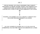
- FIG. 2 is a flow chart that depicts an example computer-implemented method for deghosting seismic data based on pressure measurements.
- FIG. 3 is a flow chart that depicts an example computer-implemented method for deghosting seismic data based on pressure and velocity measurements.
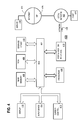
- FIG. 4 depicts an example computer system for processing seismic data.
- Techniques are described herein for processing seismic data to reduce an effect of at least a portion of seismic energy that reflected off of the surface of the water.
- the described techniques use a mixed domain inversion approach where the processing is performed in a discrete domain of measurement locations.
- the functionality described herein may be provided by the performance of a method by specialized software and/or hardware operating on one or more computing devices, by a set of one or more stored instructions that, when executed, cause performance of the method, or by a set of one or more machines configured with specialized hardware and/or software to perform the method.
- FIG. 1 depicts a specialized vessel 100 equipped with example seismic survey equipment for collecting seismic data.
- a seismic survey ship may deploy streamers behind the ship 100 as depicted in FIG. 1 .
- Each streamer 110 trails behind ship 100 as the ship 100 moves forward (in the direction of arrow 102), and each streamer may include multiple receivers 114.
- Receivers 114 may be evenly spaced or located at non-even locations, depending upon a particular implementation.
- Each streamer 110 may further include one or more diverters 118 and programmable depth controllers that pull the streamer out to an operating offset distance from the ship's path and down to an operating depth.
- Streamers 110 may be up to several kilometers long, and are usually constructed in sections. As one non-limiting example, a streamer 110 may include multiple sections that are 25 to 100 meters in length and that include groups of up to 35 or more uniformly spaced receivers. The number and length of sections and the number of receivers per streamer may vary, depending upon a particular implementation. Each streamer 110 may include electrical or fiber-optic cabling for interconnecting receivers 114 and the seismic equipment on ship 100. Data may be digitized near receivers 114 and transmitted to ship 100 through the cabling.
- seismic survey ship 100 also tows on or more sources 112.
- sources 112 may be towed by other source vessels, or sources 112 may be otherwise disposed in the body of water in any manner appropriate to the survey.
- Examples of source 112 include, without limitation, an impulse source or a vibratory source. Other types of sources 112 may be used, depending upon a particular implementation.
- Receivers 114 may include different types of sensors, depending upon a particular implementation. Example sensors include, without limitation, hydrophones and geophones.
- Source 112 and receivers 114 typically deploy below the ocean's surface 104. Processing equipment aboard the ship controls the operation of the source and receivers and records the acquired data.
- Seismic surveys provide data for imaging below the ocean surface 104 (also called the “upper surface” of the ocean) and include subsurface structures such as structure 106, which lies below the ocean floor 108 (also called the “lower surface” of the ocean or the “sea bottom”). Certain seismic characteristics of recorded seismic data are indicative of oil and/or gas reservoirs or other features beneath the ocean floor 108.
- source 112 emits seismic waves 116 that are reflected where there are changes in acoustic impedance contrast due to subsurface structure 106 (and other subsurface structures).
- the reflected waves are detected by a pattern of receivers 114.
- an image of subsurface structure 106 can be obtained after appropriate data processing.
- Data processing may include the techniques for calculating particle acceleration, velocity, and/or displacement data described above.
- seismic survey ship 100 includes both hydrophones and geophones and is equipped with or in communication with computing equipment for deghosting seismic data collected by the hydrophones and geophones. In another embodiment, seismic survey ship 100 includes only hydrophones and is equipped with or in communication with computing equipment for deghosting seismic data collected by the hydrophones. If seismic survey ship 100 is in communication with computing equipment, the computing equipment may be located on another vessel or on land. For example, the ship may be in wireless communication with the computing equipment over a network, such as a network that utilizes satellites or radio waves to transmit electronic signals between the seismic survey ship 100 and the computing equipment. In other embodiments, the data may be collected and recorded on survey ship 100 or elsewhere, and then later processed on land.
- specially configured computing device(s) obtain seismic data that describes seismic energy that has propagated or traversed through media, including water and optionally surface or subsurface layer(s), to measurement locations in the water.
- the seismic data includes pressure data that describes time-variant pressures at measurement locations in the water.
- the computing device(s) process the seismic data using wavefield decomposition or deghosting techniques to reduce an effect of at least a portion of the seismic energy that reflected off of the (upper) surface of the water.
- the processing is performed in a discrete domain that includes or is the measurement locations.
- the processed seismic data may be used to generate a map of one or more surfaces of the media through which the seismic energy has propagated.
- the processed seismic data may be used to generate a map of a surface of the earth and/or a subsurface of the earth.
- FIG. 2 is a flow chart that depicts an example computer-implemented method for deghosting seismic data based on pressure measurements.
- one or more specially configured computing devices obtain seismic data that describes time-variant pressures caused by seismic energy that propagated through water and reflected off of surface or subsurface layers to reach measurement points.
- the computing devices may be configured to receive the seismic data from the hydrophones themselves, or from a database or other data repository that stores pressure information that was collected from hydrophones over a period of time.
- the seismic data may be obtained automatically without any user intervention to the sensors, the data repository, or input to the computing devices.
- the user may make various selections, settings, or other changes to the sensors, the data repository, or the computing devices as the data is collected.
- the computing devices deghost the seismic data in a discrete domain that includes the measurement locations.
- the deghosting operation may be performed automatically without any user intervention with respect to the data obtained by the computing devices. Alternatively, the user may make various selections, settings, or other changes to optimize the deghosting operation.
- the deghosted seismic data is used to visualize or otherwise analyze the surface or subsurface layers.
- the analysis may be performed by a human user viewing output from the computing devices.
- the output may include some initial automated analysis, or may include a summary of a complete automated analysis without requiring additional human analysis.
- the automated analysis may indicate whether or not hydrocarbon or some other substance is expected to be in the measured areas.
- the automated analysis may also provide a likelihood of the presence of hydrocarbon or the other substance.
- a visualization engine operating on the computing devices may be configured to visualize, automatically or in response to user input, the deghosted seismic data by displaying a topographical map of the surface or subsurface.
- the data may be mapped in three dimensions with additional information displayed using colors or glyphs.
- the map interface may support rotation, panning, and zooming to aid in a human component of the analysis.
- an apparatus is specially configured to process the seismic data.
- the apparatus may include an interface configured to obtain the seismic data that describes seismic energy that has propogated through the water and optionally surface or subsurface layers to measurement locations in the water.
- the apparatus may also include a computer system including memory and processor(s) for processing the seismic data using wavefield decomposition to reduce an effect of a portion of the seismic energy that reflected off of an upper surface of the water layer.
- the computer system may be configured to process the seismic data in a discrete domain that includes or is the measurement locations.
- one or more non-transitory storage media store instructions for processing seismic data. When executed by processor(s), the instructions cause processing the seismic data to reduce an effect of at least a portion of the seismic energy that reflects off the surface of the water.
- the seismic data may be processed in a discrete domain of finite measurements that excludes locations or ranges of locations at which the seismic data was not measured or is otherwise not available.
- the discrete domain may exclude locations along gaps between active or operating sensors. In the example, if operating sensors are 10 meters apart, then locations along the 10 meters may be excluded from the discrete domain. As another example, the discrete domain may exclude locations of non-operating sensors. In the example, if the sensors are 20 meters apart, then a non-operating sensor may create a gap of 40 meters rather than 20 meters.
- the discrete domain includes measurement locations on one side of a source but not locations on another side of the source.
- the measurement locations may correspond to sensors that are being towed behind the boat while the boat is performing seismic testing.
- the discrete domain includes measurement locations beyond a threshold distance of a source but not within the threshold distance of the source. For example, sensors might not be placed too close (within a threshold distance) to the source because the dynamic range of many sensors cannot accommodate measurement of both signals that are close to the source and signals that have reflected off of the sea floor.
- the techniques using a discrete domain do not require measurements to be assumed or interpolated for the other side of the boat, within a threshold distance from the boat, or for other locations that are not being measured. Therefore, using the discrete domain may avoid artifacts, which correspond to artificial measurements rather than actual measurements.
- the artifacts would be created when the data is transformed from the measurements (e.g. space-time) domain to a spectral domain (e.g. wavenumber-frequency), because such transformation creates artifacts if data is missing from a computation in a continuous domain.
- Prior techniques have assumed that all of the data was present before transformation rather than mapping only on the data that was measured.
- Methods of data reconstruction of missing seismic data in a discrete domain may be based on the Polya-Plancherel theorem, which states that the Fourier transform of a band-limited function is an analytic function and determined completely by the values within any finite part of the Fourier domain. More specifically, if the data is band-limited in the spatial Fourier domain, its counterpart in the spatial domain has an infinite support. Using this formulation, the missing offsets can be obtained from the data itself, without using any information about the subsurface or using any particular interpolation method.
- the implementation of the Polya-Plancherel theorem leads to an integral equation that can be solved using a conjugate gradient scheme. In what follows, vectors or matrices of any rank > 1 are printed in bold fonts x.
- Equations (1) and (2) indicate time domain quantities.
- the Laplace parameter s the frequency parameter
- s the frequency parameter
- ⁇ T ⁇ 1 for t ⁇ T , 1 / 2 for t ⁇ ⁇ T , 0 for t ⁇ ⁇ T ⁇ .
- Spectral notches in the recorded seismic data occur when destructive interference takes place between seismic waves with particular combinations of frequencies and wavenumbers.
- the Fourier-type set of deghosting equations is solved for these frequencies f where spectral notches occur, then, the measured signal for those combinations of frequencies and wavenumbers is zero, since only background noise is recorded.
- the inversion process becomes unstable. This instability then results in irreparable artifacts being introduced into the results of the seismic wavefield decomposition used for deghosting.
- the method of the invention employs a Laplace frequency parameter s that is a complex variable with both real and imaginary parts.
- the term "complex" will be used to designate that the Laplace frequency parameter has both real and imaginary parts, as in Equation (4).
- This complex Laplace frequency parameter s may be used in the Laplace and spectral domain transforms and in the deghosting equations described herein.
- Capital symbols like H in Equation (5) refer to wave number domain quantities.
- the index l is not tied to any direction, it is just meant to enumerate the different spatial positions.
- the restriction is that H is spatially band-limited.
- measurement locations are uniformly sampled in both x 1 - and x 2 -dimensions.
- An efficient implementation can be set up for irregularly sampled measurement locations with a 2D version of the Nonuniform Fast Fourier Transform.
- ⁇ ⁇ x 1 R is in-line receiver sampling distance.
- ⁇ ⁇ x 2 R is cross-line receiver sampling distance.
- Equation (12) reads where both h and H are column vectors and is a matrix. Equation (12) may be solved for a given h using the C onjugate G radient N ormal R esidue ("CGNR") method, an iterative scheme that is known in the field of numerical linear algebra. For later use it is noted that CGNR actually deals with the system rather than equation (13a), where is the adjoint of matrix that is the elements of the adjoint are
- CGNR constructs a series of approximations h k and H k to respectively h and H such that the norm of the residual error reduces in size for increasing k , ⁇ r k +1 ⁇ ⁇ ⁇ r k ⁇ .
- P is a (block-)diagonal matrix called the preconditioner.
- P is set to the identity matrix, but for joint interpolation and deghosting describied in the later sections it is not.
- the interpolation scheme described is modified such that it can be used for simultaneous interpolation and deghosting pressure.
- the incident field known as direct wave in the art
- the deghosted pressure is called P up as the receiver ghost is downgoing. What is more, in marine acquisition, streamers are located deeper than the sources, so the incident field may be purely downgoing. Hence the upgoing pressure P up might not be distinguished from the scattered part of the upgoing pressure P sct , up .
- the upgoing field P up can be solved from equation (20) by a CGNR scheme similar to equations (15a)-(17b) with h ⁇ p sct and H ⁇ P up , while
- the scheme may be preconditioned.
- An additional element of this disclosure is another modified version of the interpolation scheme described in an earlier section, this time to be used for simultaneous interpolation and up/down separation of dual sensor data.
- L is called the composition matrix.
- equation (25) can be solved with a CGNR scheme similar to equations (15a)-(17b), where, h ⁇ q , and H ⁇ Y .
- h ⁇ q , and H ⁇ Y alterations change the size of involved matrix and vectors.
- FIG. 3 is a flow chart that depicts an example computer-implemented method for deghosting seismic data based on pressure and velocity measurements.
- one or more specially configured computing devices obtain seismic data that describes time-variant pressures and time-variant particle velocities caused by seismic energy that propagated through water and reflected off of surface or subsurface layers to reach measurement points.
- the computing devices may be configured to receive the seismic data from the hydrophones and geophones themselves, or from a database or other data repository that stores pressure information that was collected from hydrophones and geophones over a period of time.
- the seismic data may be obtained automatically without any user intervention to the sensors, the data repository, or input to the computing devices.
- Steps 302 and 304 of FIG. 3 are similar to steps 202 and 204 of FIG. 2 , except that the seismic data is deghosted using both pressure measurements and particle velocity measurements.
- the techniques described herein are implemented by one or more special-purpose computing devices.
- the special-purpose computing devices may be hard-wired to perform the techniques, or may include digital electronic devices such as one or more application-specific integrated circuits (ASICs) or field programmable gate arrays (FPGAs) that are persistently programmed to perform the techniques, or may include one or more general purpose hardware processors programmed to perform the techniques pursuant to program instructions in firmware, memory, other storage, or a combination.
- ASICs application-specific integrated circuits
- FPGAs field programmable gate arrays
- Such special-purpose computing devices may also combine custom hard-wired logic, ASICs, or FPGAs with custom programming to accomplish the techniques.
- the special-purpose computing devices may be desktop computer systems, portable computer systems, handheld devices, server computers or any other device that incorporates hard-wired and/or program logic to implement the techniques.
- FIG. 4 is a block diagram that depicts a computer system 400 upon which an embodiment of the invention may be implemented.
- Computer system 400 includes one or more buses 402 or other communication mechanism for communicating information, and a hardware processor 404 coupled with bus 402 for processing information.
- Hardware processor 404 may be, for example, a general purpose microprocessor.
- Computer system 400 also includes a main memory 406, such as a random access memory (RAM) or other dynamic storage device, coupled to bus 402 for storing information and instructions to be executed by processor 404.
- Main memory 406 also may be used for storing temporary variables or other intermediate information during execution of instructions to be executed by processor 404.
- Such instructions when stored in non-transitory storage media accessible to processor 404, render computer system 400 into a special-purpose machine that is customized to perform the operations specified in the instructions.
- Computer system 400 further includes a read only memory (ROM) 408 or other static storage device coupled to bus 402 for storing static information and instructions for processor 404.
- ROM read only memory
- a storage device 410 such as a magnetic disk, optical disk, or solid-state drive is provided and coupled to bus 402 for storing information and instructions.
- Computer system 400 may be coupled via bus 402 to a display 412, such as a cathode ray tube (CRT), for displaying information to a computer user.
- a display 412 such as a cathode ray tube (CRT)
- An input device 414 is coupled to bus 402 for communicating information and command selections to processor 404.
- cursor control 416 is Another type of user input device
- cursor control 416 such as a mouse, a trackball, or cursor direction keys for communicating direction information and command selections to processor 404 and for controlling cursor movement on display 412.
- This input device typically has two degrees of freedom in two axes, a first axis (e.g., x) and a second axis (e.g., y), that allows the device to specify positions in a plane.
- Computer system 400 may implement the techniques described herein using customized hard-wired logic, one or more ASICs or FPGAs, firmware and/or program logic which in combination with the computer system causes or programs computer system 400 to be a special-purpose machine. According to one embodiment, the techniques herein are performed by computer system 400 in response to processor 404 executing one or more sequences of one or more instructions contained in main memory 406. Such instructions may be read into main memory 406 from another storage medium, such as storage device 410. Execution of the sequences of instructions contained in main memory 406 causes processor 404 to perform the process steps described herein. In alternative embodiments, hard-wired circuitry may be used in place of or in combination with software instructions.
- Non-volatile media includes, for example, optical disks, magnetic disks, or solid-state drives, such as storage device 410.
- Volatile media includes dynamic memory, such as main memory 406.
- Common forms of storage media include, for example, a magnetic disk solid-state flash memory, magnetic tape or any other magnetic data storage medium, a CD-ROM or any other optical data storage medium, a PROM, an EPROM, a FLASH-EPROM or any other memory chip or cartridge.
- Storage media is distinct from but may be used in conjunction with transmission media.
- Transmission media participates in transferring information between storage media.
- transmission media includes coaxial cables, copper wire and fiber optics, including the wires that comprise bus 402.
- transmission media can also take the form of acoustic or light waves, such as those generated during radio-wave and infra-red data communications.
- Various forms of media may be involved in carrying one or more sequences of one or more instructions to processor 404 for execution.
- the instructions may initially be carried on a magnetic disk or solid-state drive of a remote computer.
- the remote computer can load the instructions into its dynamic memory and send the instructions over a network.
- Bus 402 carries the data to main memory 406, from which processor 404 retrieves and executes the instructions.
- the instructions received by main memory 406 may optionally be stored on storage device 410 either before or after execution by processor 404.
- Computer system 400 also includes a communication interface 418 coupled to bus 402.
- Communication interface 418 provides a two-way data communication coupling to a network link 420 that is connected to a local network 422.
- communication interface 418 may be a network interface card, an integrated services digital network (ISDN) card, cable modem, satellite modem, or a modem to provide a data communication connection to a corresponding type of telephone line.
- ISDN integrated services digital network
- communication interface 418 may be a local area network (LAN) card to provide a data communication connection to a compatible LAN.
- LAN local area network
- Wireless links may also be implemented.
- communication interface 418 sends and receives electrical, electromagnetic or optical signals that carry digital data streams representing various types of information.
- Computer system 400 can send messages and receive data, including program code, through the network(s), network link 420 and communication interface 418.
- a server 430 might transmit a requested code for an application program through Internet 428, ISP 426, local network 422 and communication interface 418.
- the received code may be executed by processor 404 as it is received, and/or stored in storage device 410, or other non-volatile storage for later execution.
- a wavefield is decomposed into up and down (ghost) components at a sensor. Similar equations can also be applied to decompose the wavefield into up and down components at the source, using equation 1 as a starting point for two or more independent measurements of the pressure wavefield, recorded at two or more different depths.
Landscapes
- Engineering & Computer Science (AREA)
- Remote Sensing (AREA)
- Physics & Mathematics (AREA)
- Life Sciences & Earth Sciences (AREA)
- Acoustics & Sound (AREA)
- Environmental & Geological Engineering (AREA)
- Geology (AREA)
- General Life Sciences & Earth Sciences (AREA)
- General Physics & Mathematics (AREA)
- Geophysics (AREA)
- Geophysics And Detection Of Objects (AREA)
Applications Claiming Priority (1)
| Application Number | Priority Date | Filing Date | Title |
|---|---|---|---|
| US13/552,611 US9335430B2 (en) | 2012-07-18 | 2012-07-18 | Wave field separation by mixed domain inversion |
Publications (2)
| Publication Number | Publication Date |
|---|---|
| EP2687873A2 true EP2687873A2 (de) | 2014-01-22 |
| EP2687873A3 EP2687873A3 (de) | 2015-10-28 |
Family
ID=48803415
Family Applications (1)
| Application Number | Title | Priority Date | Filing Date |
|---|---|---|---|
| EP13176940.8A Withdrawn EP2687873A3 (de) | 2012-07-18 | 2013-07-17 | Wellenfeldtrennung durch Mischdomäneninversion |
Country Status (6)
| Country | Link |
|---|---|
| US (1) | US9335430B2 (de) |
| EP (1) | EP2687873A3 (de) |
| AU (1) | AU2013206767B2 (de) |
| BR (1) | BR102013018178B1 (de) |
| MX (1) | MX336972B (de) |
| SG (2) | SG196719A1 (de) |
Families Citing this family (14)
| Publication number | Priority date | Publication date | Assignee | Title |
|---|---|---|---|---|
| US10101477B2 (en) * | 2013-12-17 | 2018-10-16 | Cgg Services Sas | System and method for performing seismic exploration with multiple acquisition systems |
| EP3137926A4 (de) * | 2014-04-28 | 2017-12-13 | Westerngeco LLC | Rekonstruktion eines wellenfeldes |
| US9355463B1 (en) * | 2014-11-24 | 2016-05-31 | Raytheon Company | Method and system for processing a sequence of images to identify, track, and/or target an object on a body of water |
| MX381934B (es) | 2015-05-01 | 2025-03-13 | Reflection Marine Norge As | Prospección con fuentes directivas de vibradores marinos. |
| WO2016179206A1 (en) | 2015-05-05 | 2016-11-10 | Schlumberger Technology Corporation | Removal of acquisition effects from marine seismic data |
| MX392202B (es) | 2015-12-02 | 2025-03-21 | Schlumberger Technology Bv | Tendido de sensores sismicos terrestres con pares de sensores sismicos de multiples componentes adyacentes en promedio a una distancia de al menos veinte metros. |
| CN109923441B (zh) | 2016-03-24 | 2020-12-01 | 沙特阿拉伯石油公司 | 使用l1反演同时进行地震拖缆数据的波场重建和接收器去伪 |
| GB2566240A (en) | 2016-06-15 | 2019-03-06 | Schlumberger Technology Bv | Systems and methods for acquiring seismic data with gradient data |
| US10871586B2 (en) | 2017-05-17 | 2020-12-22 | Cgg Services Sas | Device and method for multi-shot wavefield reconstruction |
| US10996361B2 (en) | 2018-09-07 | 2021-05-04 | Saudi Arabian Oil Company | Adaptive receiver deghosting for seismic streamer |
| CN109506767B (zh) * | 2018-10-24 | 2020-12-08 | 西北工业大学 | 一种对水下入侵目标引起声场异常的实时检测方法 |
| US11307317B2 (en) * | 2019-07-02 | 2022-04-19 | Saudi Arabian Oil Company | Systems and methods for data acquisition design of source and receiver locations |
| US11320557B2 (en) | 2020-03-30 | 2022-05-03 | Saudi Arabian Oil Company | Post-stack time domain image with broadened spectrum |
| CN115270644B (zh) * | 2022-09-30 | 2023-01-17 | 武汉理工大学 | 一种智能船舶节能航行编队方法、电子设备和存储介质 |
Citations (1)
| Publication number | Priority date | Publication date | Assignee | Title |
|---|---|---|---|---|
| US20110110189A1 (en) | 2009-11-12 | 2011-05-12 | Riyanti Christina D | Method for full-bandwidth deghosting of marine seismic streamer data |
Family Cites Families (5)
| Publication number | Priority date | Publication date | Assignee | Title |
|---|---|---|---|---|
| US4486865A (en) | 1980-09-02 | 1984-12-04 | Mobil Oil Corporation | Pressure and velocity detectors for seismic exploration |
| US5621700A (en) | 1996-05-20 | 1997-04-15 | Schlumberger Technology Corporation, Geco-Prakla Div. | Method for attenuation of reverberations using a pressure-velocity bottom cable |
| US7359283B2 (en) | 2004-03-03 | 2008-04-15 | Pgs Americas, Inc. | System for combining signals of pressure sensors and particle motion sensors in marine seismic streamers |
| US7986586B2 (en) | 2008-04-08 | 2011-07-26 | Pgs Geophysical As | Method for deghosting marine seismic streamer data with irregular receiver positions |
| US9025413B2 (en) * | 2009-12-07 | 2015-05-05 | Pgs Geophysical As | Method for full-bandwidth source deghosting of marine seismic streamer data |
-
2012
- 2012-07-18 US US13/552,611 patent/US9335430B2/en not_active Expired - Fee Related
-
2013
- 2013-07-03 SG SG2013052089A patent/SG196719A1/en unknown
- 2013-07-03 SG SG10201510715WA patent/SG10201510715WA/en unknown
- 2013-07-10 AU AU2013206767A patent/AU2013206767B2/en not_active Ceased
- 2013-07-16 BR BR102013018178-1A patent/BR102013018178B1/pt not_active IP Right Cessation
- 2013-07-17 MX MX2013008332A patent/MX336972B/es active IP Right Grant
- 2013-07-17 EP EP13176940.8A patent/EP2687873A3/de not_active Withdrawn
Patent Citations (1)
| Publication number | Priority date | Publication date | Assignee | Title |
|---|---|---|---|---|
| US20110110189A1 (en) | 2009-11-12 | 2011-05-12 | Riyanti Christina D | Method for full-bandwidth deghosting of marine seismic streamer data |
Non-Patent Citations (2)
| Title |
|---|
| FOKKEMA, J.T.; VAN DEN BERG, P.M.: "Seismic applications of acoustic reciprocity", 1993, ELSEVIER |
| VAN BORSELEN, R.G.; VAN DEN BERG, P.M.; FOKKEMA, J.T.: "A conjugate gradient construction of missing offsets", SEG, 1996 |
Also Published As
| Publication number | Publication date |
|---|---|
| EP2687873A3 (de) | 2015-10-28 |
| BR102013018178A2 (pt) | 2015-06-30 |
| US20140022860A1 (en) | 2014-01-23 |
| AU2013206767B2 (en) | 2017-01-12 |
| MX2013008332A (es) | 2014-02-06 |
| SG10201510715WA (en) | 2016-01-28 |
| US9335430B2 (en) | 2016-05-10 |
| MX336972B (es) | 2016-02-05 |
| AU2013206767A1 (en) | 2014-02-06 |
| BR102013018178B1 (pt) | 2018-01-02 |
| SG196719A1 (en) | 2014-02-13 |
Similar Documents
| Publication | Publication Date | Title |
|---|---|---|
| US9335430B2 (en) | Wave field separation by mixed domain inversion | |
| CN110462445B (zh) | 地球物理深度学习 | |
| EP4042210B1 (de) | Bestimmung von eigenschaften einer unterirdischen formation unter verwendung einer schallwellengleichung mit einer reflektivitätsparametrisierung | |
| US9829592B2 (en) | Seismic imaging with visco-acoustic reverse-time migration using pseudo-analytical method | |
| KR102020759B1 (ko) | Q-보상된 전 파동장 반전 | |
| CN101556339B (zh) | 对不规则接收机位置海洋地震拖缆数据进行消重影的方法 | |
| US9229123B2 (en) | Method for handling rough sea and irregular recording conditions in multi-sensor towed streamer data | |
| EP2992360B1 (de) | Deghosting mit adaptiven operatoren | |
| US8352190B2 (en) | Method for analyzing multiple geophysical data sets | |
| CN102121997B (zh) | 用于海洋地震拖缆数据的完全带宽源消幻影的方法和设备 | |
| EP2396675B1 (de) | Rekonstruktion eines seismischen wellenfeldes | |
| US11294087B2 (en) | Directional Q compensation with sparsity constraints and preconditioning | |
| AU2013206025B2 (en) | Surface-related multiple elimination for depth-varying streamer | |
| CN102062874B (zh) | 用于海洋地震拖缆数据的完全带宽消幻影的方法 | |
| US8531914B2 (en) | Method of imaging a target area of the subsoil from walkaway type data | |
| US9234977B2 (en) | Processing collected survey data | |
| US20160327668A1 (en) | Interferometry-bsed imaging and inversion | |
| US10379245B2 (en) | Method and system for efficient extrapolation of a combined source-and-receiver wavefield | |
| AU2013201070B2 (en) | Methods and systems for deghosting marine seismic wavefields using cost-functional minimization | |
| CN121127773A (zh) | 使用延迟时间信息分析模型精度和更新模型的系统与方法 | |
| EP3198308B1 (de) | Verarbeitung seismischer daten | |
| Roberts et al. | Investigation into the use of 2D elastic waveform inversion from look‐ahead walk‐away VSP surveys |
Legal Events
| Date | Code | Title | Description |
|---|---|---|---|
| PUAI | Public reference made under article 153(3) epc to a published international application that has entered the european phase |
Free format text: ORIGINAL CODE: 0009012 |
|
| AK | Designated contracting states |
Kind code of ref document: A2 Designated state(s): AL AT BE BG CH CY CZ DE DK EE ES FI FR GB GR HR HU IE IS IT LI LT LU LV MC MK MT NL NO PL PT RO RS SE SI SK SM TR |
|
| AX | Request for extension of the european patent |
Extension state: BA ME |
|
| RAP1 | Party data changed (applicant data changed or rights of an application transferred) |
Owner name: PGS GEOPHYSICAL AS |
|
| PUAL | Search report despatched |
Free format text: ORIGINAL CODE: 0009013 |
|
| RIC1 | Information provided on ipc code assigned before grant |
Ipc: G01V 1/36 20060101AFI20150917BHEP |
|
| AK | Designated contracting states |
Kind code of ref document: A3 Designated state(s): AL AT BE BG CH CY CZ DE DK EE ES FI FR GB GR HR HU IE IS IT LI LT LU LV MC MK MT NL NO PL PT RO RS SE SI SK SM TR |
|
| AX | Request for extension of the european patent |
Extension state: BA ME |
|
| 17P | Request for examination filed |
Effective date: 20160421 |
|
| RBV | Designated contracting states (corrected) |
Designated state(s): AL AT BE BG CH CY CZ DE DK EE ES FI FR GB GR HR HU IE IS IT LI LT LU LV MC MK MT NL NO PL PT RO RS SE SI SK SM TR |
|
| 17Q | First examination report despatched |
Effective date: 20181114 |
|
| GRAP | Despatch of communication of intention to grant a patent |
Free format text: ORIGINAL CODE: EPIDOSNIGR1 |
|
| INTG | Intention to grant announced |
Effective date: 20200504 |
|
| STAA | Information on the status of an ep patent application or granted ep patent |
Free format text: STATUS: THE APPLICATION IS DEEMED TO BE WITHDRAWN |
|
| 18D | Application deemed to be withdrawn |
Effective date: 20200915 |