EP2687917A2 - Ressort spiral de pièce d'horlogerie et conception dudit ressort pour la concentricité - Google Patents
Ressort spiral de pièce d'horlogerie et conception dudit ressort pour la concentricité Download PDFInfo
- Publication number
- EP2687917A2 EP2687917A2 EP13176889.7A EP13176889A EP2687917A2 EP 2687917 A2 EP2687917 A2 EP 2687917A2 EP 13176889 A EP13176889 A EP 13176889A EP 2687917 A2 EP2687917 A2 EP 2687917A2
- Authority
- EP
- European Patent Office
- Prior art keywords
- hairspring
- section
- limb
- cross
- terminal end
- Prior art date
- Legal status (The legal status is an assumption and is not a legal conclusion. Google has not performed a legal analysis and makes no representation as to the accuracy of the status listed.)
- Granted
Links
Images

















Classifications
-
- G—PHYSICS
- G04—HOROLOGY
- G04B—MECHANICALLY-DRIVEN CLOCKS OR WATCHES; MECHANICAL PARTS OF CLOCKS OR WATCHES IN GENERAL; TIME PIECES USING THE POSITION OF THE SUN, MOON OR STARS
- G04B17/00—Mechanisms for stabilising frequency
- G04B17/04—Oscillators acting by spring tension
- G04B17/06—Oscillators with hairsprings, e.g. balance
- G04B17/066—Manufacture of the spiral spring
-
- G—PHYSICS
- G04—HOROLOGY
- G04B—MECHANICALLY-DRIVEN CLOCKS OR WATCHES; MECHANICAL PARTS OF CLOCKS OR WATCHES IN GENERAL; TIME PIECES USING THE POSITION OF THE SUN, MOON OR STARS
- G04B17/00—Mechanisms for stabilising frequency
- G04B17/04—Oscillators acting by spring tension
- G04B17/06—Oscillators with hairsprings, e.g. balance
-
- Y—GENERAL TAGGING OF NEW TECHNOLOGICAL DEVELOPMENTS; GENERAL TAGGING OF CROSS-SECTIONAL TECHNOLOGIES SPANNING OVER SEVERAL SECTIONS OF THE IPC; TECHNICAL SUBJECTS COVERED BY FORMER USPC CROSS-REFERENCE ART COLLECTIONS [XRACs] AND DIGESTS
- Y10—TECHNICAL SUBJECTS COVERED BY FORMER USPC
- Y10T—TECHNICAL SUBJECTS COVERED BY FORMER US CLASSIFICATION
- Y10T29/00—Metal working
- Y10T29/49—Method of mechanical manufacture
- Y10T29/49579—Watch or clock making
- Y10T29/49581—Watch or clock making having arbor, pinion, or balance
Definitions
- the invention concerns a new design for a hairspring of a mechanical timepiece. More particularly, the present invention relates to a hairspring and a method of design thereof for increased concentricity during the operation of a mechanical timepiece.
- a hairspring is a key component in a mechanical timepiece.
- a hairspring is one of the two main components of an oscillator of a timepiece, the other being the balance wheel.
- the oscillator provides the means of time regulation via its simple harmonic motion.
- a balance wheel acts as the inertial element, and is engaged with the inner terminal of a spiral-shaped hairspring.
- the spiral geometry of a hairspring is generally provided in the form of an Archimedean spiral, generally having a constant pitch.
- the outer terminal of the hairspring is generally fixedly attached to a fixed stud.
- the hairspring provides a restoring torque to the balance wheel that is proportional to the wheel's displacement from an equilibrium position, and equations of motion may be utilised to describe a linear second-order system thereof.
- the equilibrium position of an oscillator is defined as the angular position of the balance wheel such that when the balance wheel is static, that is when the net torque applied by the hairspring to the balance wheel is zero.
- the resulting oscillator is isochronous, this meaning its natural frequency is independent of its amplitude.
- isochronous is an important property for an oscillator used in a timepiece as it requires regular torque input from an escapement to compensate for dissipative effects of friction.
- the torque provided by the escapement may not be constant due to a number of factors, which directly affects the oscillator amplitude.
- an isochronous oscillator provides a more reliable and stable time regulation.
- the spiral turnings of a hairspring for a timepiece are maintained as concentric as possible when the balance wheel rotates about its equilibrium position for reasons including:
- hairspring concentricity may be improved by modifying the geometry of the inner and outer terminal curves based on Phillips and Lossier mathematical models for hairspring design.
- Breguet has implementing such theories in its Breguet over-coil for the outer terminal.
- the over-coil uses a modified outermost turning which is raised and curved inwardly.
- this method can only maintain partial concentricity, and production the required shape in the outermost turning increases manufacturing difficulties and costs.
- hairspring concentricity may be improved by stiffening a section of the hairspring using an angle strip. Difficulties with such a hairspring include difficulty in mass production, and such a hairspring remains an academic curiosity.
- Patek Philippe stiffened a hairspring section in its Spiromax hairspring using a strip of variable width to achieve the stiffening effect.
- Patek Philippe also developed and patented a design methodology ( patent number EP 03009603.6 ) by calculating the location of the center of mass when the hairspring is relaxed. The stiffening is achieved design by a widening of the outer side on the outermost turning of the hairspring.
- the Young's modulus determines the spring constant and ultimately the natural frequency of the oscillator. Any variation of the hairspring's Young's modulus with temperature will negatively impact the oscillator's ability to reliably regulate time.
- Nivarox is a metallic alloy having a Young's modulus that is extremely low, but not zero, in respect of sensitivity to temperature variations.
- thermo-compensation The process of de-sensitizing the hairspring's Young's modulus with respect to temperature variation is defined as thermo-compensation.
- Hairspring concentricity may be increased utilizing micro-fabrication techniques based on theory, numerical simulation, or experimentation.
- the Patek Philippe Spiromax is an example of a silicon hairspring with a section of increased strip width in the outermost turning near the outer terminal, placed and sized to increase hairspring concentricity.
- Micro-fabrication technology may also allow application of a thin coat of silicon dioxide on a silicon hairspring for thermo-compensation purposes.
- the Young's modulus of silicon decreases with rise in temperature while that of silicon dioxide tends to increase.
- the present invention provides a method of increasing concentricity in use of a spiral hairspring mechanical timepiece; the hairspring having an inner terminal end portion for engagement with a collet and an outer terminal end portion for engagement with a stud, a first limb portion extending from the inner terminal end portion towards the outer terminal end portion, and a stiffening portion positioned at the outer turn of the hairspring and having a cross-sectional second moment of area different to that of the first limb portion; such that the bending stiffness of the stiffened portion has a greater bending stiffness than that of the single limb portion; wherein said method including the steps of:
- the cost function may the integral of the magnitude of the stud reaction force over the entire range of the amplitude of the rotation of hairspring in use or the maximum value of the magnitude of the stud reaction force over the entire range of the amplitude of the rotation of hairspring in use,
- the cost function may also be the integral of the magnitude of the hairspring's center of mass location, relative to the hairspring's center of mass location when the balance wheel angle is zero over the entire range of the amplitude of the rotation of hairspring in use, or the maximum value of the magnitude of the hairspring's center of mass location, relative to the hairspring center of mass location when the amplitude of rotation is zero, over the entire range of the amplitude of the rotation of hairspring in use.
- the cross-section second moments of area for a modified first portion and stiffening portion of the hairspring are based on the position location along the hairspring strip, the arc length of the modified portions of the hairspring, and a function that determines the cross-section second moment of area variation along the modified portions of the hairspring.
- the cross-section second moment of area variation is substantially constant.
- the cross-section second moment of area variation may be based on a polynomial function, a trigonometric function, or a discontinuous function of two or more piecewise continuous functions.
- the optimization algorithm used may be based on the gradient descent method requiring the computation of the gradient of the cost function with respect to the design parameters.
- the present invention provides a spiral hairspring for mechanical timepiece having an inner terminal end portion for engagement with a collet and an outer terminal end portion for engagement with a stud, a first limb portion extending from the inner terminal end portion towards the outer terminal end portion, and a stiffening portion positioned at the outer turn of the hairspring and having a cross-sectional second moment of area different to that of the first limb portion; wherein the cross-sectional second moments of area of the first portion and the stiffening portion is determined by the method of the first aspect.
- the single limb portion and the two or more spaced apart limb portions of the stiffening portion are of rectangular cross-section, and have the same width as each other and the same height as each other.
- the single limb portion and the stiffening portion are formed from a first material, and further comprising an outer coating layer formed from a second material.
- the first material has a first Young's Modulus and second material has a second Young's modulus, the first and second Young's Moduli having opposite temperature dependencies, and the single limb portion and the stiffening portion and the thickness of the outer coating layer are sized such that the elastic properties of the hairspring are desensitized to temperature variations.
- the first material is silicon and the second material is silicon dioxide.
- the single limb section may be of a substantially constant pitch, and one of the limb portions of the stiffening portion is of said pitch.
- the radially innermost limb portion is of said pitch.
- the single limb section is preferably of a substantially constant pitch, and two adjacent limb portions of the stiffening portion are substantially equidistant to the path of the said pitch.
- the spacing between two adjacent limb portions of the stiffening portion is substantially constant.
- a stiffening portion may be disposed between two single limb portions.
- the single limb portions and the innermost limb portion of the stiffening portion may be of the same pitch.
- the outermost limb portion of the stiffening portion may be of the same pitch as one adjacent single limb portion, and the innermost limb portion of the stiffening portion is of the same pitch as the adjacent limb portion of the stiffening portion.
- the stiffening portion may be disposed at the outer terminal portion of the hairspring, and each one of the limb portions of the stiffening portion have a terminal end.
- the adjacent single limb portion is preferably of substantially constant pitch, and one of the limb portions of the stiffening portion is of said pitch.
- the innermost limb portions of the stiffening portion is of said pitch.
- the outer limb portions of the stiffening portion may substantially shorter than the adjacent inner limb portion of the stiffening portion.
- an outer one of the limb portion of the stiffening portion is substantially longer than the adjacent inner limb portion of the stiffening portion.
- the stiffening portion may comprises less than one half of a spiral turn.
- Adjacent limb portions of the stiffening portion may be interconnected intermediate the ends of the stiffening portion.
- the single limb portion and the two or more spaced apart limb portions of the stiffening portion are preferably substantially coplanar.
- the present patent proposes hairspring design based on one or more stiffened section such that the entire operating range of the oscillator is considered, typically for a balance wheel angle from -330 to +330 degrees.
- the metric for concentricity can be the variation in the position of the center of mass or the reaction force at the stud over the entire operating range. This metric is used as the cost function for an automatic optimization algorithm which systematically varies the strip section parameters to achieve the maximum possible concentricity for a given hairspring geometry.
- the present invention provides a spiral hairspring for a mechanical timepiece, said hairspring comprising:
- the single limb portion and the two or more spaced apart limb portions of the stiffening portion are of rectangular cross-section, and have the same width as each other and the same height as each other.
- the single limb portion and the stiffening portion are formed from a first material, and further comprising an outer coating layer formed from a second material.
- the first material has a first Young's Modulus and second material has a second Young's modulus, the first and second Young's Moduli having opposite temperature dependencies, and the single limb portion and the stiffening portion and the thickness of the outer coating layer are sized such that the elastic properties of the hairspring are desensitized to temperature variations.
- the first material is silicon and the second material is silicon dioxide.
- the single limb section may be of a substantially constant pitch, and one of the limb portions of the stiffening portion may be of said pitch.
- the radially innermost limb portion may be of said pitch.
- the single limb section may be of a substantially constant pitch, and two adjacent limb portions of the stiffening portion are preferably substantially equidistant to the path of the said pitch.
- the spacing between two adjacent limb portions of the stiffening portion is substantially constant.
- a stiffening portion may be disposed between two single limb portions.
- the single limb portions and the innermost limb portion of the stiffening portion are of the same pitch.
- the outermost limb portion of the stiffening portion may of the same pitch as one adjacent single limb portion, and the innermost limb portion of the stiffening portion may be of the same pitch as the adjacent limb portion of the stiffening portion.
- the stiffening portion is disposed at the outer terminal portion of the hairspring, and each one of the limb portions of the stiffening portion have a terminal end.
- the adjacent single limb portion is of substantially constant pitch, and one of the limb portions of the stiffening portion is of said pitch.
- the innermost limb portions of the stiffening portion is of said pitch.
- An outer limb portion of the stiffening portion may be substantially shorter than the adjacent inner limb portion of the stiffening portion.
- an outer one of the limb portion of the stiffening portion is substantially longer than the adjacent inner limb portion of the stiffening portion.
- the stiffening portion comprises less than one half of a spiral turn.
- the adjacent limb portions of the stiffening portion may be interconnected intermediate the ends of the stiffening portion.
- the single limb portion and the two or more spaced apart limb portions of the stiffening portion are preferably substantially coplanar.
- the present invention provides a spiral hairspring for a mechanical timepiece, said hairspring comprising:
- the single limb portion and the two or more spaced apart limb portions of the stiffening portion are of rectangular cross-section, and have the same width as each other and the same height as each other.
- the single limb portion and the stiffening portion are formed from a first material, and further comprising an outer coating layer formed from a second material.
- the first material has a first Young's Modulus and second material has a second Young's modulus, the first and second Young's Moduli having opposite temperature dependencies, and the single limb portion and the stiffening portion and the thickness of the outer coating layer are sized such that the elastic properties of the hairspring are desensitized to temperature variations.
- the first material is silicon and the second material is silicon dioxide.
- the single limb section may be of a substantially constant pitch, and one of the limb portions of the stiffening portion may be of said pitch.
- the radially innermost limb portion may be of said pitch.
- the single limb section may be of a substantially constant pitch, and two adjacent limb portions of the stiffening portion are preferably substantially equidistant to the path of the said pitch.
- the spacing between two adjacent limb portions of the stiffening portion is substantially constant.
- a stiffening portion may be disposed between two single limb portions.
- the single limb portions and the innermost limb portion of the stiffening portion are of the same pitch.
- the outermost limb portion of the stiffening portion may of the same pitch as one adjacent single limb portion, and the innermost limb portion of the stiffening portion may be of the same pitch as the adjacent limb portion of the stiffening portion.
- the stiffening portion is disposed at the outer terminal portion of the hairspring, and each one of the limb portions of the stiffening portion have a terminal end.
- the adjacent single limb portion is of substantially constant pitch, and one of the limb portions of the stiffening portion is of said pitch.
- the innermost limb portions of the stiffening portion is of said pitch.
- An outer limb portion of the stiffening portion may be substantially shorter than the adjacent inner limb portion of the stiffening portion.
- an outer one of the limb portion of the stiffening portion is substantially longer than the adjacent inner limb portion of the stiffening portion.
- the stiffening portion comprises less than one half of a spiral turn.
- the adjacent limb portions of the stiffening portion may be interconnected intermediate the ends of the stiffening portion.
- the single limb portion and the two or more spaced apart limb portions of the stiffening portion are preferably substantially coplanar.
- the stiffening portion if appropriately sized and positioned, can be used to improve the hairspring concentricity.
- the present invention allows substantially complete thermo-compensation of a silicon hairspring with a silicon dioxide coating because each side-by-side branch of a multi-strip spiral section can maintain the same width as the other branches of the other spiral sections.
- the present invention allows for ease of manufacture so as to achieve the temperature compensation effect, as the silicon dioxide thickness required for total thermo-compensation varies according to the width of the silicon strip, and current manufacturing technology only permits the coating of silicon dioxide of uniform thickness.
- the present invention allows substantially complete thermo-compensation of a silicon hairspring with a silicon dioxide coating because each side-by-side branch of a multi-strip spiral section can maintain the same width as the other branches of the other spiral sections.
- the present invention allows for ease of manufacture so as to achieve the temperature compensation effect, as the silicon dioxide thickness required for total thermo-compensation varies according to the width of the silicon strip, and current manufacturing technology only permits the coating of silicon dioxide of uniform thickness.
- FIG. 1 for illustrative and explanatory purposes a simplified schematic diagram of traditional hairspring 10 at its relaxed state having a total of 13.5 turnings is shown.
- the hairspring turnings consist of two sections namely the main body section 11a and outer section 11b.
- the main body section 11a forms an Archimedes spiral having constant pitch with its inner terminal connected to a collet 12.
- the collet 12 is in turn rigidly connected to a balance wheel (not shown).
- the outer section 11b has a significantly increased pitch to allow room for the stud 13 placement. All portions of 11a and 11b have a constant cross section.
- the line 14 presents the connection point between the collet 12 and hairspring main b sections. ody section 11a which allows the reader to better track the collet 12 rotation angle.
- the traditional hairspring 10 is only an example of the many possible hairspring shape, but this example would be used for reference in the rest of this document.
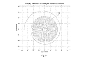
- the traditional hairspring 10 of Figure 1 is shown as being in one direction and represented as hairspring 20, which is under contractive deformation whereby collet 21 has rotated 330 degrees clockwise, which is a typical oscillation amplitude.
- the overall size of the hairspring footprint has decreased, but more importantly the deformation is not concentric with the pitch on the stud 22 side being much greater than that on the opposite side.
- the traditional hairspring 10 of Figure 1 is shown as being deformed in an opposite direction to that as shown in Figure 2 , and is represented by hairspring 30.
- the hairspring 30 is under expansive deformation where the collet 31 has rotated 330 degrees counter-clockwise.
- the size of the overall hairspring footprint has increased, but more importantly the deformation is also not concentric with the pitch on the stud 32 side being much smaller than that on the opposite side.
- the pitch over certain areas of the hairspring may become negative under deformation, away from the stud 22 in hairspring 20 and toward the stud 32 in hairspring 30, implying contact between adjacent turnings with subsequent damage.
- FIG. 4 there is shown a schematic representation of an embodiment of a hairspring 40 according to the present invention, having modified sections 41a and 41b as an example.
- Hairspring isochronism can be improved by modifying the bending stiffness of selected sections of the hairspring strip.
- One manner in which to achieve this is by varying the strip cross section, and the micro-fabrication technology increases ease of manufacture by modifying the hairspring strip width.
- a hairspring can have one or more distinct modified sections.
- the first step is to clearly define the design parameters we can vary to achieve optimal results.
- each modified section 41a or 41b requires at least three design parameters to define the geometry of the modified section: the modified second moment of area I a , the arc length L a of the modified section, and the location ⁇ a of the modified section.
- the parameter I a can be defined as a ratio compared to the second moment of area of the rest of the hairspring strip.
- the parameter L a can be defined as the length of the modified section or as the angular span in polar coordinates.
- the parameter ⁇ a can be measured relative to the stud 42 or the collet connection 43 locations as the arc distance or as the angular distance in polar coordinate.
- the number of parameters may be greater than three if the modified second moment of area I a is a complex function of the modified section arc length or angular span.
- the functions in question may be continuous functions such as polynomial or trigonometric functions, or a discontinuous combination of piecewise continuous functions.
- the second moment of area of the modified sections may have either an increased or decreased second moment of area in comparison to that of the rest of the hairspring strip.
- An automatic optimization algorithm can be designed to maximize the hairspring concentricity by varying the aforementioned design parameters that defines the geometry of the modified section or sections.
- a typical optimization algorithm adjusts the design or system parameters so as to minimize or maximize a predefined cost function, which may be subject to certain constraints.
- the cost function may be computed via a computer model of the mechanism in question using the design parameters as inputs.
- the algorithm assesses whether the cost function is satisfactory. If not, the algorithm will adjust the design parameters based on a predefined set of laws; the new design parameters are used as inputs for the computer model to compute a new cost function.
- the cycle is then repeated until the algorithm determines that the cost function is satisfactory with its corresponding optimized design parameters.
- This routine can be used to optimize the hairspring modified sections for maximum concentricity.
- the optimization algorithm requires a well-defined cost function that reflects the level of hairspring concentricity.
- the drift of the hairspring center of mass is defined as the hairspring center of mass location at a given collet rotation angle ⁇ relative to its location at ⁇ equals to zero.
- X ⁇ ⁇ 0 L ⁇ A s ⁇ x s ⁇ ⁇ - x s ⁇ 0 d s ⁇ 0 L ⁇ A s ⁇ ds
- Y ⁇ ⁇ 0 L ⁇ A s ⁇ y s ⁇ ⁇ - y s ⁇ 0 d s ⁇ 0 L ⁇ A s ⁇ ds
- variable s is the arc position along the hairspring strip.
- A(s) is the cross-section area at arc position s .
- the variables x(s , ⁇ ) and y(s , ⁇ ) define the x and y positions of the strip at arc position s and collet angle ⁇ . .
- L is the total arc length of the hairspring.
- X( ⁇ ) and Y( ⁇ ) are the drifts of the center of mass in the x and y directions, respectively, relative to the center of mass of the relaxed hairspring.
- Eq. 1 and 2 only determine the drift of the center of mass at a particular collet angle ⁇ .
- a single metric J that reflects the center of mass drift over the entire oscillator operating range can be defined by taking the integral of the magnitude of the drift from ⁇ cw , to ⁇ ccw where ⁇ cw and ⁇ ccw typically equal -330 and 330 degrees, respectively.
- J ⁇ ⁇ ccw ⁇ cw X 2 ⁇ + Y 2 ⁇ d ⁇ ⁇ cw - ⁇ ccw
- the cost function J can be described as the average drift in the hairspring center of mass, the minimization of which is correlated to the maximization of the hairspring concentricity.
- the collet angle ⁇ is discretized over N evenly-spaced values, meaning only N simulations are required to compute an approximate value for J approx .
- a large value for N implies a more accurate approximation for the cost function.
- Eq. 5 essentially turns the optimization problem into a type of mini-max problem which in this context may be simpler to implement.
- Another well-defined cost function that reflects the level of hairspring concentricity is the magnitude of the reaction force at the stud.
- the reaction force at the stud can be computed via a computer simulation of the hairspring for a certain collet angle ⁇ .
- R x ( ⁇ ) and R y ( ⁇ ) are the stud reaction forces in the x and y directions, respectively.
- This cost function can also be described as the average stud reaction force, the minimization of which is equivalent to the maximization of the hairspring concentricity.
- the cost function from Eq. (6) can also be approximated by discretizing ⁇ into N evenly-spaced values and then using the trapezoid rule to approximate the integral.
- both the center of mass drift and the stud reaction force can be used to determine the level of hairspring concentricity in the automatic optimization algorithm.
- a search algorithm needs to efficiently adjust the design parameters I a , L a , ⁇ a , I b , L b , ⁇ b , etc. to achieve optimization.
- the suffixes a and b stand for the first and second modified sections with additional possible modified sections.
- the gradient descent method is known to be one of the most efficient and popular.
- the gradient descent method computes the gradient of one of the aforementioned cost function J .
- ⁇ J ⁇ J ⁇ I a ⁇ J ⁇ L a ⁇ J ⁇ ⁇ a ⁇ J ⁇ I b ⁇ J ⁇ L b ⁇ J ⁇ ⁇ b ...
- the subscript in the design parameter vector is the iteration number, and the variable ⁇ is the step size.
- This update rule will cause the cost function to gradually approach a local minimum after given sufficient iterations.
- the step size ⁇ can be adjusted in the middle of the optimization routine depending on the proximity to the local minimum.
- the gradient descent method requires an initial guess of the design parameters at the start of the optimization routine. An initial guess that is sufficiently close to the solution can drastically reduce the optimization time.
- One possible method to obtain a good estimate of the initial guess is to perform a coarse brute-force search over a reasonable range of the design parameters.
- An independent optimization algorithm in its own right, the brute-force search computes the cost function over the range of design parameters to find the minimum cost function.
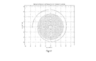
- the x-axis and y-axis are the iteration number and cost function history, respectively.
- the cost function is defined as the integral of the stud reaction force over collet angle ⁇ from -330 to +330 degrees, the nominal operating range of a typical oscillator.
- One curve shows the optimization history of a hairspring with a single stiffened section in the outermost turning, and the other curve shows that with two stiffened sections also in the outermost turning.
- reaction force at the stud for the optimized section hairsprings (ii) and (iii) is significantly lower than a hairspring having a constant second moment of area (i).
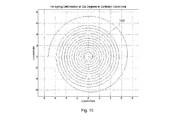
- the hairsprings 90 and 100 have their collets rotated by 330 degrees clockwise and counter-clockwise, respectively.
- the enhanced concentricity is visually noticeable and clearly demonstrated when compared to those of Figure 2 and Figure 3 .
- Figure 11 and Figure 12 show the deformation geometry of the hairspring 110, 120, with two optimized stiffened sections.
- the hairsprings 110 and 120 have their collets rotated by 330 degrees clockwise and counter-clockwise, respectively.
- the concentricity is a further improvement over the hairspring with one optimized stiffened section shown in comparison with those of Figure 9 and Figure 10 .
- the increased concentricity achieved by the aforementioned automatic optimization algorithm allows the implementation of a novel type of hairspring with multiple arms.
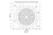
- FIG. 13 an example of a multi-arm hairspring 130 with two arms 131a and 131b is shown.
- the two arms 131a and 131b extend from a central collet 132.
- the arms 131a and 131b terminate at outer terminals 132a and 132b, respectively.
- the dual-arm hairspring 130 is axially-symmetric with arm 131a being identical to arm 131b.
- the hairspring 200 includes an inner terminal portion 210 for engagement with a collet 220 and an outer terminal portion 230 for engagement with a start 240, a first limb portion 250 extending from the inner terminal end portion 210 towards the outer terminal portion 230, and a stiffening portion 260 positioned at the outer turn of the hairspring 200.
- the stiffening portion is a bifurcated section including an inner limb 262 and outer limb 264, and a strut extending therebetween 266.
- the stiffening portion 260 is stiffened by increasing the 2 nd moment of area by utilizing the spaced apart to bifurcated limbs 262, 264, which collectively increase the 2 nd moment of area in this portion of the spring.
- the cross-sectional dimensions of the first limb portion and the stiffening portion are both the same, and as such, the first limb portion and each of the two limbs of the stiffening portion, 262 and 264, each have the same cross-sectional area.
- the first limb portion and the stiffening portion are formed from the same material and have the same cross-sectional area, and in view of the Young's Modulus being constant due to the hairspring being formed from a single piece of material, the temperature effect on various portions of the hairspring is the same in respect of alteration of Young's Modulus as a function of change in temperature.
- the hairspring 200 in the present embodiment is formed by micro-fabrication techniques, which allow for high dimensional accuracy in the production of such items or articles.
- the micro-fabrication technique in respect of the present embodiment allows for temperature desensitization, by using a first material having a first Young's Modulus for the formation of the hairspring and a second material as a coating material having a second Young's Modulus, the first and second Young's Moduli having opposite temperature dependencies and as such, the outer coating layer may be suitably sized and have a thickness such that elastic properties of the hairspring are desensitized to temperature variation.
- Suitable materials for forming the hairspring according to the present embodiment are silicon, with a silicon dioxide layer.
- the stiffening portion is included in the hairspring.
- the dimensions of the stiffening portion may be optimized according to the method of the present invention, so as to provide a suitable stiffness such that deformation of the spring is minimized during rotation, wandering mass is reduced. This may be achieved by utilizing a minimization of a cost function as described above in relation to the present invention.
- the 2nd moment of area of the bifurcated section can be designed to be equivalent to that of a stiffened section with increased width.
- a hairspring whose nominal width and height are bo and h, respectively. Compare two hairspring sections. One section has a single strip of increased width n times that of the b0. The other section has two bifurcated strips, each of the same width as the nominal value b0 and separated by a distance d as measured from the centerline of each strip.
- the optimization algorithm may be readily adapted for both the widened and bifurcated sections.
- the section width is used as one of the design parameters to be varied in the optimization algorithm.
- the bifurcated strip distance is used as one of the design parameters to be varied. Note that the two methods can be used interchangeably by using Eq. (12).
- a two-section optimized stiffened section in accordance with the present invention has a reduced centre of wandering mass in comparison with both a one optimized stiffened position and the Spiromax hairspring.
- FIG. 16 there is shown a comparison between the reaction force at the start of hairsprings throughout their general range of motion between -330 and 330 degrees whereby a constant 2nd moment of area, a one optimized stiffened portion, a two optimized stiffened portion and Spiromax hairspring is made.
- a single optimized stiffened section hairspring for which the stiffness is optimized according to the present invention has a lower stud reaction force than that of the Spiromax hairspring.
- a hairspring having two optimized stiffened portions in accordance with the present invention has a substantially lower stud reaction force, this reaction force being almost zero, in comparison with the other hairspring.
- the stud reaction force is indicative of the reaction force at the bearings of the collet, and as will be understood by those skilled in the art, this reduces friction and wear at the collect, and hence increases longevity.
- a hairspring having two optimized stiffened portions according to the present invention results in a hairspring having lower wandering mass and very low reaction force at the stud.
- the concentricity of such a hairspring according to the present invention is increased, thus providing an improved isochronous hairspring for a timepiece accordingly.
- the axially-symmetric layout of the multi-arm hairspring can further improve isochronism because any radial force imparted by one arm on the collet is neutralized by the net radial force imparted by the other arms. If the effect of gravity is neglected, the balance staff bearings theoretically do not experience any radial force, resulting in an oscillator that is essentially free of bearing friction.
- the present invention provides a hairspring for a timepiece which may be produced with high dimensional and mechanical accuracy, by use of micro-fabrication techniques.
- the hairspring according to the present invention provides increased concentricity by providing a stiffening position which reduces wandering of the mass of the hairspring about the axis of rotation during use, such reduction in wandering reduces radial inertial effects of the hairspring due to acceleration and motion, thus reducing radial forces at the central bearing.
- the hairspring according to the present invention provides increased isochronousity.
- Euler-Bernoulli beam formula is widely used in the watch industry to estimate the hairspring bending stiffness.
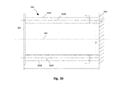
- a cantilever structure 310 comprised of two beams 311A, 311B connected side-by-side in parallel. It must be emphasized that the term "parallel" is utilized throughout the specification, this term is understood to extend to elements of a structure connected in a side-by-side layout, which is not necessarily parallel in the strict geometric definition.
- This cantilever structure 310 demonstrates its effect on the structure's bending stiffness, defined as the ratio between the applied moment and a beam's resultant deflection.
- the right end of the cantilever structure 310 has a clamped boundary condition 315, resisting displacement and rotation.
- the left end of the cantilever structure 310 is free but has a plate 314 affixed to both beams 311A, 311B to ensure that they bend together and cannot translate or rotate with respect to each other.
- the two beams 311A, 311B each have a length of L, width of b, and height of h.
- the two beams 311A, 311B are also separated by a constant distance of d when measured from their centerlines 312A, 312B.
- the cantilever structure 310 also has a neutral axis 313, which in this case is equidistant between the beam centerlines 312A, 312B.
- the cantilever structure 310 has a higher bending stiffness when compared to a single cantilever beam of the same length and cross-section as each of the beams 311A, 311B due to the two following reasons:
- nb the ratio d : b for simplification of equation.
- k 2 Ehb 3 2 ⁇ L ⁇ 1 3 + n 2
- n the value of n must be greater than 1 or the two beams 311A, 311B will overlap.
- the minimum feasible value of k 2 always greater than k 1 for a planar cantilever structure 310.
- the minimum feasible value of k 2 defined as k 2,min , is eight times the value of k 1 .
- Equations (13) and (14) show the effectiveness of increasing the cantilever structure's 310 bending stiffness by arranging two beams 311A, 311B in a side-by-side arrangement.
- the parallel axis theorem may also be applied to a cantilever structure 310 having more than two beams 311A, 311B in a side-by-side layout and yield the same conclusion.
- cantilever structure 310 with side-by-side beams 311A, 311B even when the beam distance d is not constant, although the derivation of the structure's 310 bending stiffness will be more complex and require techniques such as calculus for computation.
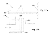
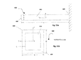
- a cantilever structure 320 having a single beam 321 of uniform cross-section with all reference coordinates based on the right-hand rule of solid mechanics.
- the beam 321 has a width of b , height of h , and length of L .
- the left end 322 is free, and the right end 323 is clamped.
- the cross-section 324 of the beam 321 shows a silicon core 325 with a silicon dioxide coating 326 of thickness ⁇ ..
- E Si,0 , E SiO2,0 , e Si , and e SiO2 are all constants, and ⁇ T is the temperature change.
- the constants E Si,0 , E SiO2,0 , e Si , and e SiO2 have a numerical value of approximately 148 GPa, 72.4 GPa, -60 ppm/K, and 215 ppm/K at room temperature, respectively.
- Equation (18) describes the sensitivity of the E eq with respect to ⁇ T , and to achieve total thermo-compensation, it needs to be set to zero by varying ⁇ .
- the optimal ⁇ : b ratio is fairly stable at approximately 6% for a cross-section with a silicon core and silicon dioxide coating.
- the results demonstrate that total thermo-compensation is theoretically feasible for a silicon hairspring of uniform cross-section via a coating of silicon dioxide.
- a cantilever structure 330 having two beams 331A, 331B of different cross-sections 334A, 334B, in series. All reference coordinates are based on the right-hand rule according to established solid mechanics.
- the beam 331A has a free end 332 at its left end and is engaged with a beam 331B at its right end 333.
- the beam 331B is attached to beam 331A at its left end 333 and has a clamped boundary condition 334 at its right end.
- the beam 331A has a width of b A , a height of h A , and a length of L A
- the beam 331B has a width of b B , a height of h B , and a length of L B .
- the cross-section 335A of the beam 331A shows a silicon core 336A with a silicon dioxide coating 337A of thickness ⁇
- the cross-section 335B of the beam 331B shows a silicon core 336B with a silicon dioxide coating 337B also of thickness ⁇ .
- Both cross-sections 335A, 335B have the same silicon dioxide coating thickness as current micro-fabrication technology cannot achieve variable coating thickness on the same component.
- E eq,A ( ⁇ T) and E eq,B ( ⁇ T) corresponds to the equivalent Young's moduli for beams 331A and 331B, respectively.
- K A ( ⁇ T) and K B ( ⁇ T) are the bending stiffness of the beams 331A and 331B, respectively.
- Equation (30) describes the sensitivity of the K eq with respect to ⁇ T , and the coefficients N 2 , N 1 , N 0 , D 2 , D 1 , and D 0 are defined as follows.
- the silicon dioxide coating thickness must be set such that Equation (30) becomes zero for all values of ⁇ T. Assuming the denominator of Equation (30) is non-zero, it becomes only necessary to set the numerator of Equation (30) to zero for all values of ⁇ T .
- Equation (30) is a quadratic function of ⁇ T , meaning the numerator can equal to zero for only two values of ⁇ T . Equation (30) proves that total thermo-compensation is impossible for a cantilever structure 330 with two beams 331A, 331B of different cross-section, in series.
- thermo-compensation is theoretically impossible for a silicon hairspring of variable cross-section.
- thermo-compensation is theoretically feasible for a hairspring with side-by-side strips.
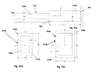
- Beam section 342 has two beams 342A, 342B connected in a side-by-side layout. All reference coordinates are based on the right-hand rule.
- the beam 341 has a free end 343 at its left end and is attached to beam section 342 at its right end 344.
- the beam section 342 has two beams 342A, 342B connected in a side-by-side layout, and the entire beam section 342 is attached to beam 341 at its left end and has a clamped boundary condition 345 at its right end. All the beams 341,342A, 342B have the same cross-section 346 with a width of b , height of h , and a silicon dioxide coating of thickness ⁇
- Beam 341 has length of L A
- beams 342A, 342B have a length of L B .
- the beam section 342 has a higher bending stiffness than beam 341 due to the side-by-side arrangement.
- the beam section 341, 342 lengths L A and L B and the distance d between the beams 342A and 342B it is possible to design the cantilever structure 340 such that it has the same equivalent bending stiffness as the cantilever structure 330 in Figure 22a and 22b .
- each beam 341, 342A, 342B has the same cross-section geometry
- the silicon dioxide coating thickness to beam width ratio ⁇ : b is the same for all the beams 341, 342A, 342B.
- Total thermo-compensation for any one beam section 341, 342 means the same for the other beam section. This proves that total thermo-compensation for a silicon hairspring accordingly to the present invention with side-by-side strips, is theoretically feasible.
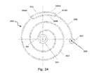
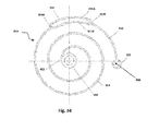
- a hairspring 350 having a multi-strip spiral section 355 side-by-side branches 355A, 355B of a rectangular section, with a single outer terminal 357 connected to a stud 358.
- the hairspring 350 consists of a collet 351 at the centre.
- the inner primary strip 353 spirals outward from the inner terminal 352 attached to the collet 351 until hairspring section 355 where it splits into two side-by-side branches 355A, 355B at point 354A.
- the two branches 355A, 355B re-converge at point 354B into a single outer primary strip 356 until it reaches the outer terminal 357 which is fixed and clamped.
- the hairspring section 355 with the side-by-side branches 355A, 355B has a larger bending stiffness than the inner primary strip 353 and the outer primary strip 356.
- An automatic design optimization algorithm such as gradient method can maximize the hairspring 350 concentricity by using the length and placement of section 355 and the distance between branches 355A and 355B.
- the distance between the branches 355A and 355B may be varied along the length of section 355.
- the branches 355A, 355B may, for example, diverge and converge, it being understood that the available space may be constrained to permit the spiral spring to contract and expand without adjacent turnings touching each other, and without the spring contacting other elements of the escapement.
- the hairspring 355 of the present embodiment can be of any size and shape and placed anywhere with sufficient clearance depending on the initial hairspring geometry.
- side-by-side branches 355A, 355B having a substantially constant separation distance are generally preferable so as to provide ease of calculation and optimization of spring characteristics.
- FIGS. 25 , 26 , and 27 there are shown three further embodiments of a hairspring according to the present invention, having multi-strip spiral section with two side-by-side branches. These embodiments, as will be appreciated by those skilled in the art, may readily be extended to include multi-strip spiral sections with more than two side-by-side branches.
- FIG. 25 there is shown a multi-strip spiral section arrangement 360 of a further embodiment of a hairspring according to the present invention, where both side-by-side branches 363A, 363A abruptly diverge from and then abruptly converge into a single branch of two adjacent single-strip spiral sections 361A, 361B of the hairspring
- FIG. 26 there is shown a multi-strip spiral segment 370 of another embodiment of a hairspring according to the present invention.
- the left primary strip 371A is smoothly connected to one of the side-by-side branches 373A which is in turn smoothly connected to the right primary strip 371B.
- the side-by-side branch 373A abruptly diverges from the left primary strip 371A at the point of intersection 372A and abruptly converges into the right primary strip 371B at the point of intersection 372B.
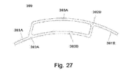
- FIG. 27 there is shown a multi-strip spiral segment 380 of yet a further embodiment of a hairspring according to the present invention.
- the left primary strip 381A is smoothly connected to one of the side-by-side branches 383B.
- the side-by-side branch 383A abruptly diverge from the left primary strip 381A at the point of intersection 382A and is smoothly connected to the right primary strip 381B.
- the side-by-side branch 383B abruptly converges into the right primary strip 381B at the point of intersection 382B.
- FIG. 28 there is shown a layout of a multi-strip spiral section 390 of yet another embodiment of the present invention, including a support strut 394.
- the side-by-side branches 393A, 393B are connected the primary strips 391A, 391B to the left and right via the points of intersection 392A, 392B, respectively.
- the side-by-side branches 393A and 393B may bend with slightly different radii of curvature. Depending on the hairspring geometry and the magnitude of the bending, the side-by-side branches 393A and 393B may be urged towards each other, and may come into contact.
- the support strut 394 prevents this from happening and has minimal impact in the statics of the multi-strip spiral section 390 if the width of the strut 394 is much smaller than the length of the spiral section 390.
- strut 394 may be utilised, depending upon the geometry, shape, size and application of the hairspring.
- FIG. 29 there is shown an alternate embodiment of a hairspring 400 according to the present invention.
- the hairspring design has a collet 401 at its centre.
- the primary strip 403 has an inner terminal 402 connected to the collet 401 and spirals outward until it reaches the multi-strip spiral section 405 at the point of intersection 404.
- the primary strip 403 then splits into two side-by-side branches 405A and 405B, each of which independently terminates in a fixed and clamped outer terminal 406A, 406B, respectively, by contrast to the embodiment as depicted in Figure 24 whereby the side-by-side branches 455A, 455B re-converge at the outer terminal.
- Euler-Bernoulli beam formula is widely used in the watch industry to estimate the hairspring bending stiffness.
- a cantilever structure 510 comprised of two beams 511A, 511B connected side-by-side in parallel. It must be emphasized that the term "parallel" is utilized throughout the specification, this term is understood to extend to elements of a structure connected in a side-by-side layout, which is not necessarily parallel in the strict geometric definition.
- An analysis of this cantilever structure 510 demonstrates its effect on the structure's bending stiffness, defined as the ratio between the applied moment and a beam's resultant deflection.
- the right end of the cantilever structure 510 has a clamped boundary condition 515, resisting displacement and rotation.
- the left end of the cantilever structure 510 is free but has a plate 514 affixed to both beams 511A, 511B to ensure that they bend together and cannot translate or rotate with respect to each other.
- the two beams 511A, 511B each have a length of L , width of b , and height of h .
- the two beams 511A, 511B are also separated by a constant distance of d when measured from their centerlines 512A, 512B.
- the cantilever structure 510 also has a neutral axis 513, which in this case is equidistant between the beam centerlines 512A, 512B.
- the cantilever structure 510 has a higher bending stiffness when compared to a single cantilever beam of the same length and cross-section as each of the beams 511A, 511B due to the two following reasons:
- nb the ratio d : b for simplification of equation.
- k 2 Ehb 3 2 ⁇ L ⁇ 1 3 + n 2
- n must be greater than 1 or the two beams 511A, 511B will overlap.
- the minimum feasible value of k 2 always greater than k 1 for a planar cantilever structure 510.
- the minimum feasible value of k 2 defined as k 2,min , is eight times the value of k 1 .
- Equations (1) and (2) show the effectiveness of increasing the cantilever structure's 510 bending stiffness by arranging two beams 511A, 511B in a side-by-side arrangement.
- the parallel axis theorem may also be applied to a cantilever structure 510 having more than two beams 511A, 511B in a side-by-side layout and yield the same conclusion.
- cantilever structure 510 with side-by-side beams 511A, 511B even when the beam distance d is not constant, although the derivation of the structure's 510 bending stiffness will be more complex and require techniques such as calculus for computation.
- a cantilever structure 620 having a single beam 621 of uniform cross-section with all reference coordinates based on the right-hand rule of solid mechanics.
- the beam 621 has a width of b , height of h , and length of L .
- the left end 622 is free, and the right end 623 is clamped.
- the cross-section 624 of the beam 621 shows a silicon core 625 with a silicon dioxide coating 626 of thickness ⁇ ..
- E Si,0 , E SiO2,0 , e Si , and e SiO2 are all constants, and ⁇ T is the temperature change.
- the constants E Si,0 , E SiO2,0 , e Si , and e SiO2 have a numerical value of approximately 148 GPa, 72.4 GPa, -60 ppm/K, and 215 ppm/K at room temperature, respectively.
- Equation (6) describes the sensitivity of the E eq with respect to ⁇ T , and to achieve total thermo-compensation, it needs to be set to zero by varying ⁇ .
- the optimal ⁇ : b ratio is fairly stable at approximately 6% for a cross-section with a silicon core and silicon dioxide coating.
- the results demonstrate that total thermo-compensation is theoretically feasible for a silicon hairspring of uniform cross-section via a coating of silicon dioxide.
- a cantilever structure 730 having two beams 731A, 731B of different cross-sections7 34A, 734B, in series. All reference coordinates are based on the right-hand rule according to established solid mechanics.
- the beam731A has a free end 732 at its left end and is engaged with a beam 731B at its right end 733.
- the beam 731B is attached to beam 731A at its left end 733 and has a clamped boundary condition 734 at its right end.
- the beam 731A has a width of b A , a height of h A , and a length of L A
- the beam 731B has a width of b B , a height of h B , and a length of L B .
- the cross-section 735A of the beam 731A shows a silicon core 736A with a silicon dioxide coating 737A of thickness ⁇
- the cross-section 735B of the beam 731B shows a silicon core 736B with a silicon dioxide coating 737B also of thickness ⁇ .
- Both cross-sections 735A, 735B have the same silicon dioxide coating thickness as current micro-fabrication technology cannot achieve variable coating thickness on the same component.
- E eq,A ( ⁇ T) and E eq,B ( ⁇ T) corresponds to the equivalent Young's moduli for beams 31A and 31B, respectively.
- K A ( ⁇ T) and K B ( ⁇ T) are the bending stiffness of the beams 31A and 31B, respectively.
- Equation (18) describes the sensitivity of the K eq with respect to ⁇ T , and the coefficients N 2 , N 1 , N 0 , D 2 , D 1 , and D 0 are defined as follows.
- the silicon dioxide coating thickness must be set such that Equation (18) becomes zero for all values of ⁇ T . Assuming the denominator of Equation (18) is non-zero, it becomes only necessary to set the numerator of Equation (18) to zero for all values of ⁇ T .
- Equation (18) is a quadratic function of ⁇ T , meaning the numerator can equal to zero for only two values of ⁇ T . Equation (18) proves that total thermo-compensation is impossible for a cantilever structure 730 with two beams 731A, 731B of different cross-section, in series.
- thermo-compensation is theoretically impossible for a silicon hairspring of variable cross-section.
- thermo-compensation is theoretically feasible for a hairspring with side-by-side strips.
- a cantilever structure 840 having two beam sections 841, 842, in series.
- Beam section 842 has two beams 842A, 842B connected in a side-by-side layout. All reference coordinates are based on the right-hand rule.
- the beam 841 has a free end 843 at its left end and is attached to beam section 842 at its right end 844.
- the beam section 842 has two beams 842A, 842B connected in a side-by-side layout, and the entire beam section 842 is attached to beam 841 at its left end and has a clamped boundary condition 845 at its right end. All the beams 841, 842A, 842B have the same cross-section 846 with a width of b , height of h , and a silicon dioxide coating of thickness ⁇ .
- Beam 841 has length of L A
- beams 842A, 842B have a length of L B .
- the beam section 842 has a higher bending stiffness than beam 841 due to the side-by-side arrangement.
- the beam section 841, 842 lengths L A and L B and the distance d between the beams 842A and 842B it is possible to design the cantilever structure 40 such that it has the same equivalent bending stiffness as the cantilever structure 830 in Figures 32a - 32c .
- a hairspring 950 according to the present invention having a multi-strip spiral section 955 side-by-side branches 955A, 955B of a rectangular section, with a single outer terminal 957 connected to a stud 958.
- the hairspring 950 consists of a collet 951 at the centre.
- the inner primary strip 953 spirals outward from the inner terminal 952 attached to the collet 951 until hairspring section 955 where it splits into two side-by-side branches 955A, 955B at point 954A.
- the two branches 955A, 955B re-converge at point 954B into a single outer primary strip 956 until it reaches the outer terminal 957 which is fixed and clamped.
- the hairspring section 955 with the side-by-side branches 955A, 955B has a larger bending stiffness than the inner primary strip 953 and the outer primary strip 956.
- An automatic design optimization algorithm such as gradient method can maximize the hairspring 950 concentricity by using the length and placement of section 55 and the distance between branches 955A and 955B as its search space.
- the distance between the branches 955A and 955B may be varied along the length of section 955.
- the branches 955A, 955B may, for example, diverge and converge, it being understood that the available space may be constrained to permit the spiral spring to contract and expand without adjacent turnings touching each other, and without the spring contacting other elements of the escapement.
- the hairspring 955 of the present embodiment can be of any size and shape and placed anywhere with sufficient clearance depending on the initial hairspring geometry.
- side-by-side branches 955A, 955B having a substantially constant separation distance are generally preferable so as to provide ease of calculation and optimization of spring characteristics.
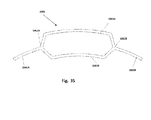
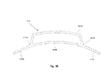
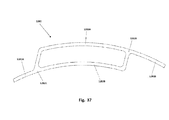
- FIGS. 35 , 36 , and 37 there are shown three further embodiments of a hairspring according to the present invention, having multi-strip spiral section with two side-by-side branches. These embodiments, as will be appreciated by those skilled in the art, may readily be extended to include multi-strip spiral sections with more than two side-by-side branches.
- FIG. 35 there is shown a multi-strip spiral section arrangement 1060 of a further embodiment of a hairspring according to the present invention, where both side-by-side branches 1063A, 1063B abruptly diverge from and then abruptly converge into a single branch of two adjacent single-strip spiral sections 1061A, 1061B of the hairspring
- FIG. 36 there is shown a multi-strip spiral segment 1170 of another embodiment of a hairspring according to the present invention.
- the left primary strip 1171A is smoothly connected to one of the side-by-side branches 1173A which is in turn smoothly connected to the right primary strip 1171B.
- the side-by-side branch 1173A abruptly diverges from the left primary strip 1171A at the point of intersection 1172A and abruptly converges into the right primary strip 1171B at the point of intersection 1172B.
- FIG. 37 there is shown a multi-strip spiral segment 1280 of yet a further embodiment of a hairspring according to the present invention.
- the left primary strip 1281A is smoothly connected to one of the side-by-side branches 1283B.
- the side-by-side branch 1283A abruptly diverge from the left primary strip 1281A at the point of intersection 1282A and is smoothly connected to the right primary strip 1281B.
- the side-by-side branch 1283B abruptly converges into the right primary strip 1281B at the point of intersection 1282B.
- FIG. 38 there is shown a layout of a multi-strip spiral section 1390 of yet another embodiment of the present invention, including a support strut 1394.
- the side-by-side branches 1393A, 1393B are connected the primary strips 1391A, 1391B to the left and right via the points of intersection 1392A,1392B, respectively.
- the side-by-side branches 1393A and 1393B may bend with slightly different radii of curvature. Depending on the hairspring geometry and the magnitude of the bending, the side-by-side branches 1393A and 1393B may be urged towards each other, and may come into contact.
- the support strut 1394 prevents this from happening and has minimal impact in the statics of the multi-strip spiral section 1390 if the width of the strut 1394 is much smaller than the length of the spiral section 1390.
- strut 1394 may be utilised, depending upon the geometry, shape, size and application of the hairspring.
- FIG 39 there is shown an alternate embodiment of a hairspring 14100 according to the present invention.
- the hairspring design has a collet 14101 at its centre.
- the primary strip 14103 has an inner terminal 14102 connected to the collet 14101 and spirals outward until it reaches the multi-strip spiral section 14105 at the point of intersection 14104.
- the primary strip 14103 then splits into two side-by-side branches 14105A and 14105B, each of which independently terminates in a fixed and clamped outer terminal 14106A, 14106B, respectively, by contrast to the embodiment as depicted in Figure 34 whereby the side-by-side branches 955A, 955B re-converge at the outer terminal.
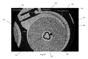
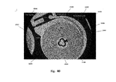
- FIG. 40 there is shown a photographic representation of an embodiment of a hairspring 15200 according to the present invention.
- the hairspring 15200 includes an inner terminal portion 15210 for engagement with a collet 15220 and an outer terminal portion 15230 for engagement with a start 15240, a first limb portion 15250 extending from the inner terminal end portion 15210 towards the outer terminal portion 15230, and a stiffening portion 15260 positioned at the outer turn of the hairspring 15200.
- the stiffening portion is a bifurcated section including an inner limb 15262 and outer limb 15264, and a strut extending therebetween 266.
- the stiffening portion 15260 is stiffened by increasing the 2 nd moment of area by utilizing the spaced apart to bifurcated limbs 15262, 15264, which collectively increase the 2 nd moment of area in this portion of the spring.
- the cross-sectional dimensions of the first limb portion and the stiffening portion are both the same, and as such, the first limb portion and each of the two limbs of the stiffening portion, 15262 and 15264, each have the same cross-sectional area.
- the first limb portion and the stiffening portion are formed from the same material and have the same cross-sectional area, and in view of the Young's Modulus being constant due to the hairspring being formed from a single piece of material, the temperature effect on various portions of the hairspring is the same in respect of alteration of Young's Modulus as a function of change in temperature.
- the hairspring 15200 in the present embodiment is formed by micro-fabrication techniques, which allow for high dimensional accuracy in the production of such items or articles.
- the micro-fabrication technique in respect of the present embodiment allows for temperature desensitization, by using a first material having a first Young's Modulus for the formation of the hairspring and a second material as a coating material having a second Young's Modulus, the first and second Young's Moduli having opposite temperature dependencies and as such, the outer coating layer may be suitably sized and have a thickness such that elastic properties of the hairspring are desensitized to temperature variation.
- Suitable materials for forming the hairspring according to the present embodiment are silicon, with a silicon dioxide layer.
- the stiffening portion is included in the hairspring.
- the dimensions of the stiffening portion may be optimized according to the method of the present invention, so as to provide a suitable stiffness such that deformation of the spring is minimized during rotation, wandering mass is reduced. This may be achieved by utilizing a minimization of a cost function as described above in relation to the present invention.
- the 2nd moment of area of the bifurcated section can be designed to be equivalent to that of a stiffened section with increased width.
- the optimization algorithm can be easily adapted for both the widened and bifurcated sections.
- the section width is used as one of the design parameters to be varied in the optimization algorithm.
- the bifurcated strip distance is used as one of the design parameters to be varied. Note that the two methods can be used interchangeably by using Eq. (12).
- the present embodiment will also achieve increased stiffening near the outer terminal in accordance with the invention, although the two side-by-side branches 15105A and 15105B do not re-converge.
- the present invention provides a hairspring for a timepiece which may be produced with high dimensional and mechanical accuracy, by use of micro-fabrication techniques.
- Micro-fabrication technology is generally limited to the manufacture of planar components. While it can theoretically produce hairsprings with Breguet-style over-coil which multiple overlapping layers, such manufacturing capability is not currently reliable and, at the very least, demands significant additional complexity to the manufacturing process.
- the hairspring according to the present invention provides increased concentricity by providing a stiffening position which reduces wandering of the mass of the cess hairspring about the axis of rotation during use, such reduction in wandering reduces radial inertial effects of the hairspring due to acceleration and motion, thus reducing radial forces at the central bearing.
- the hairspring according to the present invention provides increased isochronousity.
Landscapes
- Physics & Mathematics (AREA)
- General Physics & Mathematics (AREA)
- Engineering & Computer Science (AREA)
- Manufacturing & Machinery (AREA)
- Springs (AREA)
- Micromachines (AREA)
- Scissors And Nippers (AREA)
Applications Claiming Priority (2)
| Application Number | Priority Date | Filing Date | Title |
|---|---|---|---|
| HK12106963.6A HK1178377A2 (en) | 2012-07-17 | 2012-07-17 | Hairspring design for concentricity |
| HK12106962.7A HK1178376A2 (en) | 2012-07-17 | 2012-07-17 | Hairspring for mechanical timepiece |
Publications (3)
| Publication Number | Publication Date |
|---|---|
| EP2687917A2 true EP2687917A2 (fr) | 2014-01-22 |
| EP2687917A3 EP2687917A3 (fr) | 2018-01-24 |
| EP2687917B1 EP2687917B1 (fr) | 2025-05-28 |
Family
ID=48803412
Family Applications (1)
| Application Number | Title | Priority Date | Filing Date |
|---|---|---|---|
| EP13176889.7A Active EP2687917B1 (fr) | 2012-07-17 | 2013-07-17 | Ressort spiral de pièce d'horlogerie et conception dudit ressort pour la concentricité |
Country Status (2)
| Country | Link |
|---|---|
| US (1) | US9658598B2 (fr) |
| EP (1) | EP2687917B1 (fr) |
Families Citing this family (7)
| Publication number | Priority date | Publication date | Assignee | Title |
|---|---|---|---|---|
| CH707165B1 (fr) * | 2012-11-07 | 2016-12-30 | Patek Philippe Sa Geneve | Mouvement d'horlogerie à balancier-spiral. |
| EP2884346A1 (fr) * | 2013-12-16 | 2015-06-17 | ETA SA Manufacture Horlogère Suisse | Spiral polygonal pour un résonateur horloger |
| EP2916177B1 (fr) * | 2014-03-05 | 2018-11-07 | Nivarox-FAR S.A. | Spiral destiné à être serré par une rondelle élastique |
| JP6549251B2 (ja) * | 2015-06-03 | 2019-07-24 | ウーテーアー・エス・アー・マニファクチュール・オロロジェール・スイス | 緩急針アセンブリによる微調整を有する共振器 |
| US10317842B2 (en) * | 2016-04-25 | 2019-06-11 | Seiko Epson Corporation | Timepiece mainspring, timepiece drive device, timepiece movement, timepiece, and manufacturing method of timepiece mainspring |
| JP6721454B2 (ja) * | 2016-08-10 | 2020-07-15 | シチズン時計株式会社 | 時計用部品 |
| EP4332686A1 (fr) * | 2022-08-30 | 2024-03-06 | ETA SA Manufacture Horlogère Suisse | Spiral pour ensemble balancier-spiral d'un mouvement d'horlogerie |
Family Cites Families (10)
| Publication number | Priority date | Publication date | Assignee | Title |
|---|---|---|---|---|
| ATE307990T1 (de) * | 2002-11-25 | 2005-11-15 | Suisse Electronique Microtech | Spiraluhrwerkfeder und verfahren zu deren herstellung |
| DE60333076D1 (de) | 2003-04-29 | 2010-08-05 | Patek Philippe Sa | Unruh- und fläche Spiralfederregulator für Uhrwerk |
| CN101878454B (zh) * | 2007-11-28 | 2013-01-16 | 尤利西斯·雅典钟表及天文时计制造厂(勒洛克勒)股份有限公司 | 具有优化的热弹性系数的机械振荡器 |
| EP2233989A1 (fr) * | 2009-03-24 | 2010-09-29 | Manufacture et fabrique de montres et chronomètres Ulysse Nardin Le Locle SA | Ressort spiral et sa raquetterie |
| CH701783B1 (fr) * | 2009-09-07 | 2015-01-30 | Manuf Et Fabrique De Montres Et Chronomètres Ulysse Nardin Le Locle S A | Ressort spiral de mouvement de montre. |
| CH701846B8 (fr) * | 2009-09-21 | 2015-06-15 | Rolex Sa | Spiral plat pour balancier d'horlogerie et ensemble balancier-spiral. |
| DE102009048733A1 (de) | 2009-10-08 | 2011-04-14 | Konrad Damasko | Spiralfeder für mechanische Schwingungssysteme von Uhren |
| HK1146455A2 (en) * | 2010-03-12 | 2011-06-03 | Microtechne Research & Development Center Ltd | An oscillator system |
| EP2405312A1 (fr) * | 2010-07-09 | 2012-01-11 | Montres Breguet S.A. | Spiral de balancier à deux niveaux et à centre de masse immobile |
| EP2613206B1 (fr) * | 2012-01-05 | 2022-05-11 | Montres Breguet SA | Spiral à deux ressort-spiraux à isochronisme amélioré |
-
2013
- 2013-07-17 EP EP13176889.7A patent/EP2687917B1/fr active Active
- 2013-07-17 US US13/944,554 patent/US9658598B2/en active Active
Non-Patent Citations (1)
| Title |
|---|
| EMILE; GASTON MICHEL: "Spiraux plats concentriques sans courbes''ly", 1958, SOCIETE SUISSE CHRONOMETRIE |
Also Published As
| Publication number | Publication date |
|---|---|
| EP2687917A3 (fr) | 2018-01-24 |
| US20140022873A1 (en) | 2014-01-23 |
| EP2687917B1 (fr) | 2025-05-28 |
| US9658598B2 (en) | 2017-05-23 |
Similar Documents
| Publication | Publication Date | Title |
|---|---|---|
| EP2687917B1 (fr) | Ressort spiral de pièce d'horlogerie et conception dudit ressort pour la concentricité | |
| EP3056948B1 (fr) | Spirale de silicium | |
| US8770828B2 (en) | Oscillator system | |
| JP5350441B2 (ja) | 固定された質量中心を有するひげぜんまい | |
| US8348497B2 (en) | Flat balance spring for horological balance and balance wheel/balance spring assembly | |
| CN105980938B (zh) | 具有交叉条带的钟表谐振器 | |
| CN103543630B (zh) | 在使用螺旋游丝机械表时提高同心度的方法和螺旋游丝 | |
| US9004748B2 (en) | Balance spring with two hairsprings and improved isochronism | |
| CN104737080B (zh) | 用于钟表擒纵机构的擒纵叉机构 | |
| US10241473B2 (en) | Method for maintaining and regulating a timepiece resonator | |
| US9256206B2 (en) | Device for maintaining and regulating a timepiece resonator | |
| EP3299905B1 (fr) | Oscillateur mécanique pour un mouvement d'horloge | |
| CN111324027A (zh) | 包括至少一个挠曲轴承的时计谐振器 | |
| EP3032352A1 (fr) | Régulateur de pièce d'horlogerie, mouvement d'horlogerie et pièce d'horlogerie comportant un tel régulateur | |
| CN103543631A (zh) | 机械钟表的游丝 | |
| HK1189951A (en) | Hairspring for a timepiece and hairspring design for concentricity | |
| Thalmann et al. | Flexure pivot oscillator with intrinsically tuned isochronism | |
| Thalmann et al. | Design of a flexure rotational time base with varying inertia | |
| HK1190469A (en) | A method of increasing concentricity in use of a spiral hairspring mechanical timepiece and a hairspring | |
| HK1190469B (en) | A method of increasing concentricity in use of a spiral hairspring mechanical timepiece and a hairspring | |
| HK1190468A (en) | Hairspring for mechanical timepiece | |
| HK1187118B (en) | Balance spring with two hairsprings and improved isochronism | |
| JP2014160001A (ja) | ひげぜんまい、ムーブメント、時計及びひげぜんまいの製造方法 | |
| HK40032092B (en) | Timepiece resonator comprising at least one flexible bearing | |
| HK40032092A (en) | Timepiece resonator comprising at least one flexible bearing |
Legal Events
| Date | Code | Title | Description |
|---|---|---|---|
| PUAI | Public reference made under article 153(3) epc to a published international application that has entered the european phase |
Free format text: ORIGINAL CODE: 0009012 |
|
| AK | Designated contracting states |
Kind code of ref document: A2 Designated state(s): AL AT BE BG CH CY CZ DE DK EE ES FI FR GB GR HR HU IE IS IT LI LT LU LV MC MK MT NL NO PL PT RO RS SE SI SK SM TR |
|
| AX | Request for extension of the european patent |
Extension state: BA ME |
|
| REG | Reference to a national code |
Ref country code: HK Ref legal event code: DE Ref document number: 1189951 Country of ref document: HK |
|
| PUAL | Search report despatched |
Free format text: ORIGINAL CODE: 0009013 |
|
| AK | Designated contracting states |
Kind code of ref document: A3 Designated state(s): AL AT BE BG CH CY CZ DE DK EE ES FI FR GB GR HR HU IE IS IT LI LT LU LV MC MK MT NL NO PL PT RO RS SE SI SK SM TR |
|
| AX | Request for extension of the european patent |
Extension state: BA ME |
|
| RIC1 | Information provided on ipc code assigned before grant |
Ipc: G04B 17/06 20060101AFI20171220BHEP |
|
| STAA | Information on the status of an ep patent application or granted ep patent |
Free format text: STATUS: REQUEST FOR EXAMINATION WAS MADE |
|
| 17P | Request for examination filed |
Effective date: 20180724 |
|
| RBV | Designated contracting states (corrected) |
Designated state(s): AL AT BE BG CH CY CZ DE DK EE ES FI FR GB GR HR HU IE IS IT LI LT LU LV MC MK MT NL NO PL PT RO RS SE SI SK SM TR |
|
| STAA | Information on the status of an ep patent application or granted ep patent |
Free format text: STATUS: EXAMINATION IS IN PROGRESS |
|
| 17Q | First examination report despatched |
Effective date: 20201002 |
|
| P01 | Opt-out of the competence of the unified patent court (upc) registered |
Effective date: 20230525 |
|
| GRAP | Despatch of communication of intention to grant a patent |
Free format text: ORIGINAL CODE: EPIDOSNIGR1 |
|
| STAA | Information on the status of an ep patent application or granted ep patent |
Free format text: STATUS: GRANT OF PATENT IS INTENDED |
|
| INTG | Intention to grant announced |
Effective date: 20250124 |
|
| GRAS | Grant fee paid |
Free format text: ORIGINAL CODE: EPIDOSNIGR3 |
|
| GRAA | (expected) grant |
Free format text: ORIGINAL CODE: 0009210 |
|
| STAA | Information on the status of an ep patent application or granted ep patent |
Free format text: STATUS: THE PATENT HAS BEEN GRANTED |
|
| AK | Designated contracting states |
Kind code of ref document: B1 Designated state(s): AL AT BE BG CH CY CZ DE DK EE ES FI FR GB GR HR HU IE IS IT LI LT LU LV MC MK MT NL NO PL PT RO RS SE SI SK SM TR |
|
| REG | Reference to a national code |
Ref country code: GB Ref legal event code: FG4D |
|
| REG | Reference to a national code |
Ref country code: CH Ref legal event code: EP |
|
| REG | Reference to a national code |
Ref country code: IE Ref legal event code: FG4D Ref country code: DE Ref legal event code: R096 Ref document number: 602013086788 Country of ref document: DE |
|
| PGFP | Annual fee paid to national office [announced via postgrant information from national office to epo] |
Ref country code: GB Payment date: 20250619 Year of fee payment: 13 |
|
| PGFP | Annual fee paid to national office [announced via postgrant information from national office to epo] |
Ref country code: FR Payment date: 20250620 Year of fee payment: 13 |
|
| REG | Reference to a national code |
Ref country code: NL Ref legal event code: MP Effective date: 20250528 |
|
| PG25 | Lapsed in a contracting state [announced via postgrant information from national office to epo] |
Ref country code: ES Free format text: LAPSE BECAUSE OF FAILURE TO SUBMIT A TRANSLATION OF THE DESCRIPTION OR TO PAY THE FEE WITHIN THE PRESCRIBED TIME-LIMIT Effective date: 20250528 Ref country code: FI Free format text: LAPSE BECAUSE OF FAILURE TO SUBMIT A TRANSLATION OF THE DESCRIPTION OR TO PAY THE FEE WITHIN THE PRESCRIBED TIME-LIMIT Effective date: 20250528 |
|
| PGFP | Annual fee paid to national office [announced via postgrant information from national office to epo] |
Ref country code: DE Payment date: 20250620 Year of fee payment: 13 |
|
| REG | Reference to a national code |
Ref country code: LT Ref legal event code: MG9D |
|
| PG25 | Lapsed in a contracting state [announced via postgrant information from national office to epo] |
Ref country code: GR Free format text: LAPSE BECAUSE OF FAILURE TO SUBMIT A TRANSLATION OF THE DESCRIPTION OR TO PAY THE FEE WITHIN THE PRESCRIBED TIME-LIMIT Effective date: 20250829 Ref country code: NO Free format text: LAPSE BECAUSE OF FAILURE TO SUBMIT A TRANSLATION OF THE DESCRIPTION OR TO PAY THE FEE WITHIN THE PRESCRIBED TIME-LIMIT Effective date: 20250828 |
|
| PG25 | Lapsed in a contracting state [announced via postgrant information from national office to epo] |
Ref country code: PL Free format text: LAPSE BECAUSE OF FAILURE TO SUBMIT A TRANSLATION OF THE DESCRIPTION OR TO PAY THE FEE WITHIN THE PRESCRIBED TIME-LIMIT Effective date: 20250528 Ref country code: NL Free format text: LAPSE BECAUSE OF FAILURE TO SUBMIT A TRANSLATION OF THE DESCRIPTION OR TO PAY THE FEE WITHIN THE PRESCRIBED TIME-LIMIT Effective date: 20250528 |
|
| PG25 | Lapsed in a contracting state [announced via postgrant information from national office to epo] |
Ref country code: BG Free format text: LAPSE BECAUSE OF FAILURE TO SUBMIT A TRANSLATION OF THE DESCRIPTION OR TO PAY THE FEE WITHIN THE PRESCRIBED TIME-LIMIT Effective date: 20250528 |
|
| PG25 | Lapsed in a contracting state [announced via postgrant information from national office to epo] |
Ref country code: HR Free format text: LAPSE BECAUSE OF FAILURE TO SUBMIT A TRANSLATION OF THE DESCRIPTION OR TO PAY THE FEE WITHIN THE PRESCRIBED TIME-LIMIT Effective date: 20250528 |
|
| PGFP | Annual fee paid to national office [announced via postgrant information from national office to epo] |
Ref country code: CH Payment date: 20250801 Year of fee payment: 13 |
|
| PG25 | Lapsed in a contracting state [announced via postgrant information from national office to epo] |
Ref country code: RS Free format text: LAPSE BECAUSE OF FAILURE TO SUBMIT A TRANSLATION OF THE DESCRIPTION OR TO PAY THE FEE WITHIN THE PRESCRIBED TIME-LIMIT Effective date: 20250828 |
|
| PG25 | Lapsed in a contracting state [announced via postgrant information from national office to epo] |
Ref country code: IS Free format text: LAPSE BECAUSE OF FAILURE TO SUBMIT A TRANSLATION OF THE DESCRIPTION OR TO PAY THE FEE WITHIN THE PRESCRIBED TIME-LIMIT Effective date: 20250928 |
|
| PG25 | Lapsed in a contracting state [announced via postgrant information from national office to epo] |
Ref country code: LV Free format text: LAPSE BECAUSE OF FAILURE TO SUBMIT A TRANSLATION OF THE DESCRIPTION OR TO PAY THE FEE WITHIN THE PRESCRIBED TIME-LIMIT Effective date: 20250528 |
|
| REG | Reference to a national code |
Ref country code: AT Ref legal event code: MK05 Ref document number: 1798943 Country of ref document: AT Kind code of ref document: T Effective date: 20250528 |
|
| PG25 | Lapsed in a contracting state [announced via postgrant information from national office to epo] |
Ref country code: SM Free format text: LAPSE BECAUSE OF FAILURE TO SUBMIT A TRANSLATION OF THE DESCRIPTION OR TO PAY THE FEE WITHIN THE PRESCRIBED TIME-LIMIT Effective date: 20250528 Ref country code: DK Free format text: LAPSE BECAUSE OF FAILURE TO SUBMIT A TRANSLATION OF THE DESCRIPTION OR TO PAY THE FEE WITHIN THE PRESCRIBED TIME-LIMIT Effective date: 20250528 Ref country code: AT Free format text: LAPSE BECAUSE OF FAILURE TO SUBMIT A TRANSLATION OF THE DESCRIPTION OR TO PAY THE FEE WITHIN THE PRESCRIBED TIME-LIMIT Effective date: 20250528 |
|
| PG25 | Lapsed in a contracting state [announced via postgrant information from national office to epo] |
Ref country code: CZ Free format text: LAPSE BECAUSE OF FAILURE TO SUBMIT A TRANSLATION OF THE DESCRIPTION OR TO PAY THE FEE WITHIN THE PRESCRIBED TIME-LIMIT Effective date: 20250528 |
|
| PG25 | Lapsed in a contracting state [announced via postgrant information from national office to epo] |
Ref country code: EE Free format text: LAPSE BECAUSE OF FAILURE TO SUBMIT A TRANSLATION OF THE DESCRIPTION OR TO PAY THE FEE WITHIN THE PRESCRIBED TIME-LIMIT Effective date: 20250528 |
|
| PG25 | Lapsed in a contracting state [announced via postgrant information from national office to epo] |
Ref country code: RO Free format text: LAPSE BECAUSE OF FAILURE TO SUBMIT A TRANSLATION OF THE DESCRIPTION OR TO PAY THE FEE WITHIN THE PRESCRIBED TIME-LIMIT Effective date: 20250528 Ref country code: SK Free format text: LAPSE BECAUSE OF FAILURE TO SUBMIT A TRANSLATION OF THE DESCRIPTION OR TO PAY THE FEE WITHIN THE PRESCRIBED TIME-LIMIT Effective date: 20250528 |
|
| PG25 | Lapsed in a contracting state [announced via postgrant information from national office to epo] |
Ref country code: IT Free format text: LAPSE BECAUSE OF FAILURE TO SUBMIT A TRANSLATION OF THE DESCRIPTION OR TO PAY THE FEE WITHIN THE PRESCRIBED TIME-LIMIT Effective date: 20250528 |
|
| REG | Reference to a national code |
Ref country code: DE Ref legal event code: R097 Ref document number: 602013086788 Country of ref document: DE |
|
| PG25 | Lapsed in a contracting state [announced via postgrant information from national office to epo] |
Ref country code: LU Free format text: LAPSE BECAUSE OF NON-PAYMENT OF DUE FEES Effective date: 20250717 |
|
| REG | Reference to a national code |
Ref country code: BE Ref legal event code: MM Effective date: 20250731 |
|
| PLBE | No opposition filed within time limit |
Free format text: ORIGINAL CODE: 0009261 |
|
| STAA | Information on the status of an ep patent application or granted ep patent |
Free format text: STATUS: NO OPPOSITION FILED WITHIN TIME LIMIT |
|
| REG | Reference to a national code |
Ref country code: CH Ref legal event code: L10 Free format text: ST27 STATUS EVENT CODE: U-0-0-L10-L00 (AS PROVIDED BY THE NATIONAL OFFICE) Effective date: 20260409 |
|
| PG25 | Lapsed in a contracting state [announced via postgrant information from national office to epo] |
Ref country code: BE Free format text: LAPSE BECAUSE OF NON-PAYMENT OF DUE FEES Effective date: 20250731 |