EP2688049B1 - Voreinzugsvorrichtung eines Zahlungsterminals - Google Patents
Voreinzugsvorrichtung eines Zahlungsterminals Download PDFInfo
- Publication number
- EP2688049B1 EP2688049B1 EP13176865.7A EP13176865A EP2688049B1 EP 2688049 B1 EP2688049 B1 EP 2688049B1 EP 13176865 A EP13176865 A EP 13176865A EP 2688049 B1 EP2688049 B1 EP 2688049B1
- Authority
- EP
- European Patent Office
- Prior art keywords
- blade
- bucket
- cutting blade
- movable cutting
- collection device
- Prior art date
- Legal status (The legal status is an assumption and is not a legal conclusion. Google has not performed a legal analysis and makes no representation as to the accuracy of the status listed.)
- Not-in-force
Links
- 238000007599 discharging Methods 0.000 claims 2
- 238000006073 displacement reaction Methods 0.000 description 14
- 241001071864 Lethrinus laticaudis Species 0.000 description 11
- 230000006835 compression Effects 0.000 description 4
- 238000007906 compression Methods 0.000 description 4
- 238000010008 shearing Methods 0.000 description 4
- 230000000694 effects Effects 0.000 description 3
- 235000021183 entrée Nutrition 0.000 description 3
- 230000005484 gravity Effects 0.000 description 3
- 238000012423 maintenance Methods 0.000 description 3
- 238000010200 validation analysis Methods 0.000 description 3
- 238000005452 bending Methods 0.000 description 2
- 238000001514 detection method Methods 0.000 description 2
- 238000006386 neutralization reaction Methods 0.000 description 2
- 238000010719 annulation reaction Methods 0.000 description 1
- 230000000295 complement effect Effects 0.000 description 1
- 238000000151 deposition Methods 0.000 description 1
- 238000003780 insertion Methods 0.000 description 1
- 230000037431 insertion Effects 0.000 description 1
- 238000002955 isolation Methods 0.000 description 1
- 239000002184 metal Substances 0.000 description 1
- 238000000034 method Methods 0.000 description 1
- 238000007747 plating Methods 0.000 description 1
- 238000011084 recovery Methods 0.000 description 1
- 238000009877 rendering Methods 0.000 description 1
- 238000010079 rubber tapping Methods 0.000 description 1
- 229910001220 stainless steel Inorganic materials 0.000 description 1
- 239000010935 stainless steel Substances 0.000 description 1
Images


Classifications
-
- G—PHYSICS
- G07—CHECKING-DEVICES
- G07D—HANDLING OF COINS OR VALUABLE PAPERS, e.g. TESTING, SORTING BY DENOMINATIONS, COUNTING, DISPENSING, CHANGING OR DEPOSITING
- G07D1/00—Coin dispensers
- G07D1/02—Coin dispensers giving change
- G07D1/04—Coin dispensers giving change dispensing change equal to a sum deposited
-
- G—PHYSICS
- G07—CHECKING-DEVICES
- G07D—HANDLING OF COINS OR VALUABLE PAPERS, e.g. TESTING, SORTING BY DENOMINATIONS, COUNTING, DISPENSING, CHANGING OR DEPOSITING
- G07D11/00—Devices accepting coins; Devices accepting, dispensing, sorting or counting valuable papers
- G07D11/10—Mechanical details
- G07D11/14—Inlet or outlet ports
-
- G—PHYSICS
- G07—CHECKING-DEVICES
- G07F—COIN-FREED OR LIKE APPARATUS
- G07F1/00—Coin inlet arrangements; Coins specially adapted to operate coin-freed mechanisms
- G07F1/04—Coin chutes
- G07F1/041—Coin chutes with means, other than for testing currency, for dealing with inserted foreign matter, e.g. "stuffing", "stringing" or "salting"
- G07F1/042—Coin chutes with means, other than for testing currency, for dealing with inserted foreign matter, e.g. "stuffing", "stringing" or "salting" the foreign matter being a long flexible member attached to a coin
- G07F1/043—Cutting or trapping of the flexible member or the attached coin
Definitions
- the present invention relates to a device for depositing coins for a payment terminal, the prepayment device comprising a frame, a bucket having a coin entry opening in the bucket and a coin opening opening. stored in the bucket.
- a fraudulent method commonly used in payment terminals for payment by coins is to attach the coin to one end of a wire, before introducing it into the payment terminal through the introductory slot provided for this effect.
- the piece attached to the end of the thread then passes into the coin selector and then falls into the pre-collection bucket.
- the bucket moves to its collection position, in which the coins it contains are normally evacuated to the piggy bank under the effect of gravity.
- the part considered being attached to the end of a wire whose opposite end is held by the fraudster it can not be evacuated to the piggy bank and remains in the bucket.
- the fraudster then performs a second transaction, during which he introduces a new coin and looses the thread.
- the newly introduced piece, as well as the piece attached to its wire fall to the bottom of the bucket.
- the fraudster cancels the transaction so that the bucket moves to its position of return of money and evacuates the two pieces to the bowl, where they are recovered by the fraudster.
- This fraud system thus allows the fraudster to obtain a free parking permit for a period corresponding to the amount of the first coin introduced.
- An object of the invention is to provide a pre-collection device comprising a system for guaranteeing the collection of coins introduced into the terminal when the transaction is validated, and which is also simple and inexpensive to implement.
- a device according to the preamble of claim 1 is disclosed in DE 88 00 768 U1 .
- the subject of the invention is a pre-tapping device as described above, which comprises at least one movable cutting blade with respect to the chassis between a rest position and an active position which can be displaced at least partially through of the inlet opening between the rest position and the active position, and a moving mechanism of the movable cutting blade, able to move the movable cutting blade from its rest position to its active position so to cut an object engaged in the inlet opening of the bucket.
- the bucket is pivotally mounted relative to the frame about a bucket pivot axis between a settling position, in which it delimits a temporary coin storage volume and a coin evacuation position through the bucket. exit opening to a piggy bank of the payment terminal, the moving mechanism of the movable cutting blade being adapted to move the movable cutting blade from its rest position to its active position under the action of displacement of the bucket from its precleaning position to its evacuation position.
- the invention also relates to a payment terminal comprising a pre-collection device as defined above.
- the figure 1 schematically illustrates a portion of a payment terminal 1 comprising a pre-collection device according to the invention.
- Payment terminal means an apparatus intended to provide a product or a service in exchange for its payment made in particular by means of coins.
- Said apparatus may for example be a parking meter or a ticket dispenser.
- the coins are directed to a piggy bank, not shown, in which the coins are stored permanently until the next collection.
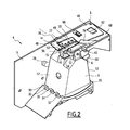
- the pre-emption device 4 according to the invention is illustrated in more detail on the figures 2 and 3 .
- the bucket 8 has for example a general bell shape comprising two side walls 12 diverging downwards.
- This inlet opening 14 is configured to receive the parts from the selector 3 and to enter the bucket 8. It is elongate in a longitudinal direction. It has for example a slot shape, including rectangular.
- the inlet opening 14 comprises, in its upper part, a duct 16 fixed relative to the frame 6 and forming part of a support piece 18 of the bucket 8 integral with the frame 6.
- coin guiding teeth 20 are distributed along a longitudinal edge 22 of the inlet opening 14. They provide guiding in the inlet opening 14 of the coins from the coin. output aperture 24 of the selector 3. These guide teeth 20 protrude upwardly from the inlet opening 14. They are in particular formed on an upper edge of the duct 16 and extend upwards to from this conduit 16.
- the bucket 8 In its lower part, the bucket 8 comprises an opening 26 for evacuating parts.
- the bucket 8 is pivotally mounted relative to the frame 6 about a bucket pivot axis noted A between a pre-settlement position, illustrated on the figure 2 , in which it delimits with the platform 10 a temporary storage volume of the coins and a position of evacuation of the coins through the discharge opening 26 towards the piggy bank, illustrated on the figure 3 .
- the pivot axis A is a horizontal axis. It is arranged in the upper part of the bucket 8.
- the pre-collection device 4 further comprises bucket displacement means 8 (not shown), configured to move the bucket 8 between its pre-settlement position and its evacuation position.
- bucket displacement means 8 are conventional. They will not be described in more detail.
- the frame 6 comprises a slot 28, for example in an arc, for guiding the bucket 8 during its movement between its different positions.
- the platform 10 comprises longitudinal ribs 30 on its inwardly facing face of the bucket 8. These ribs 30 delimit between them grooves 32 which cooperate with complementary teeth 34 formed on the bucket 8 so as to driving the pieces stored in the bucket 8 out of the platform 10 during the pivoting of the bucket 8 to its evacuation position.
- the platform 10 In the pre-paid position illustrated on the figure 2 , the platform 10 completely closes the discharge opening 26 of the bucket 8 and forms with said bucket 8 the temporary storage volume for the coins.
- This object is more particularly a wire connecting a coin contained in the bucket 8 to the coin introduction slot 2 in the payment terminal 1.
- the position of the wire in the entry opening 14 is determined by the positions relative to the opening 24 of the coin selector 3 and the inlet opening 14 of the bucket 8.
- the wire is engaged in the inlet opening 14 at an engagement zone. In the example shown, this engagement zone is located at a longitudinal end of the inlet opening 14.
- the anti-fraud system is entirely comprised within an outer casing of the payment terminal 1.
- the movable blade 36 occupies its rest position when the bucket 8 occupies its preventer position. It occupies its active position when the bucket 8 occupies its evacuation position.
- the displacement mechanism is able to move the movable cutting blade 36 from its rest position to its active position under the action of displacement of the bucket 8 from its pre-settlement position to its discharge position.
- the bucket 8 by its displacement of its pre-bending position to its discharge position, causes the movable cutting blade 36 to move from its rest position to its active position by means of the movement mechanism.
- the anti-fraud system also comprises a counterblade 40 fixed relative to the frame 6.
- the movable blade 36 is movably mounted relative to the counterblade 40.
- the blade 36 and the counterblade 40 are arranged at the inlet of the bucket 8, at a height greater than that of the inlet opening 14.
- the blade 36 is configured to cooperate with the counterblade 40 to cut the wire engaged in the inlet opening 14.
- the blade 36 and the counterblade 40 cooperate in the manner of the blades of a chisel to cut the wire by shearing.
- the counter blade 40 is arranged such that the blade 36 slides on the counterblade 40 as it moves from its rest position to its active position.
- the blade 36 and the counterblade 40 are able to shear the wire engaged in the inlet opening 14 when the blade 36 slides on the counterblade 40.
- the blade 36 is pivotally mounted relative to the frame 6 about a pivot axis marked B between its rest position and its active position.
- This axis B is vertical.
- the blade 36 is movable at least partially through the inlet opening 14 between the rest position and the active position. In the example shown, it is configured to scan only one zone of the inlet opening 14, namely the longitudinal end on the side of which is engaged the wire connected to a piece received in the bucket 8.
- the blade 36 is, in the example shown, substantially flat. It extends in a substantially horizontal plane, in particular at a height greater than that of the inlet opening 14.
- the counterblade 40 is disposed in a plane substantially normal to the plane of the blade 36. It is arranged on the along an edge 42 of the inlet opening 14.
- the blade 36 comprises an actuating zone 46 and a cutting zone 48.
- the actuating zone 46 is pivotally mounted on the frame 6.
- the cutting zone 48 forms an end of the blade 36 away from the pivoting axis B.
- the blade 36 comprises, between the cutting zone 48 and the operating zone 46, a recess 49 capable of allowing the passage of the teeth 20 during the displacement of the blade 36 towards its end. active position.
- the cutting zone 48 carries a cutting surface 50 facing the counterblade 40 and intended to cooperate with a cutting surface 52 of the counterblade 40 to cut the wire engaged in the blade. entrance opening 14.
- the cutting surface 50 has a length less than the length of the inlet opening 14. Thus, the cutting surface 50 extends only over a portion of the inlet opening 14 .
- the cutting surface 50 of the blade 36 has a V-shaped or L-shaped shape oriented towards the inlet opening 14. Thanks to this particular shape, the blade 36 is able, during its movement towards its active position, to seize the wire engaged in the inlet opening 14, and to guide against the against-blade 40.
- This V-shape also ensures the maintenance of the wire in contact with the against-blade 40 and the blade 36 to ensure the cutting of this wire by shearing when the movable cutting surface 50 crosses the fixed cutting surface 52 by sliding on it during its movement to its active position.
- the cutting surface 50 of the blade 36 comprises a movable cutting edge 56 intended to cooperate with a fixed cutting edge 58 of the counter blade 40 in order to cut the wire.
- the movable cutting edge 56 is configured to slide on the fixed cutting edge 58 as the blade 36 moves to its active position. This crossing causes the cutting of the wire trapped between the fixed cutting edge 58 and the movable cutting edge 56. Thus, the movable cutting edge 56 slides on the fixed cutting edge 58 while being in contact with it. this.
- the blade 36 and against the blade 40 are for example made of metal, especially stainless steel.
- the blade 36 and the counterblade 40 are sharpened.
- the fixed and movable cutting edges 58, 56 are sharp.
- the movable cutting edge 56 extends substantially in the plane of displacement of the blade 36, that is to say in the plane of the inlet opening 14.
- the length of the movable cutting edge 56 is less than the length of the inlet opening 14.
- the fixed cutting surface 52 is formed on an upper surface of the counterblade 40.
- the fixed cutting edge 58 is formed by the intersection between the fixed cutting surface 52 and a substantially vertical surface of the counterblade 40 on the side of the entrance opening.
- the fixed cutting surface 52 is inclined downwards away from the blade 36. It forms an angle less than 90 °, more particularly about 80 ° with a horizontal plane passing through the fixed cutting edge 58.
- the fixed cutting edge 58 extends substantially parallel to the longitudinal edge 42. It is substantially rectilinear in the example shown. It has, in the example shown, a length less than that of the inlet opening 14.
- the blade 36 In the rest position, the blade 36 is disposed away from the counter blade 40 at least at its cutting edge 56 so as to allow the passage of the wire between the blade 36 and against the blade 40, more particularly between the cutting edges 56, 58.
- the movable cutting blade 36 extends on the side of an edge 22 of the inlet opening 14, opposite to the longitudinal edge 42 along which extends the counter blade 40.
- the cutting edges 56, 58 of the blade 36 and the counterblade 40 are spaced from each other when the blade 36 is in its rest position. In particular, they extend on either side of the inlet opening 14.
- the blade 36 In the active position, the blade 36 overlaps against blade 40 over at least a part of its length. In the example shown, in the active position, the blade 36 bears against the guide teeth 20. More particularly, the cutting zone 48 of the blade 36 extends at least partially in line with the counter blade 40. The lower surface of the blade 36 contacts the fixed cutting edge 58.
- the movement mechanism of the blade 36 comprises a cam 60 integral with the bucket 8 and a counter cam 62 integral with the blade 36.
- the pivoting of the cam 60 around the pivot axis A of the bucket 8 causes the counter-cam 62 to pivot about the pivot axis B of the blade 36.
- the cam comprises a pin 60 projecting outwardly of the bucket 8 from a side wall 12 of the bucket 8.
- the cam follower 40 comprises an inclined ramp 62 projecting downwardly from of the blade 36, in particular from the actuating zone 46 of the blade 36.
- the ramp 62 is inclined so that the pivoting of the bucket 8, and thus the pin 60, around the pivot axis A towards the evacuation position generates the pivoting of the blade 36 to the active position.
- Elastic return means 66 formed, in the example shown, by a compression spring, are configured to return the blade 36 from its active position to its rest position when the bucket 8 moves from its evacuation position to its precautionary position.
- the compression spring is fixed to the blade 36, more particularly to the actuating zone 46, at one of its ends and to the frame 6, in particular to the support piece 18 of the cup 8, by the other its ends. It is compressed in the active position of the blade 36.
- the anti-fraud system comprises prestressing means capable of prestressing the movable cutting blade 36 against the counterblade 40 in a direction normal to the plane of movement of the blade 36.
- the prestressing means comprise the compression spring. More particularly, the compression spring extends along an axis inclined with respect to the plane of displacement of the blade 36 so as to urge the blade 36 towards the counterblade 40.
- the prestressing means further comprise an additional pressure member capable of biasing the counterblade 40 towards the blade 36 in the direction normal to the plane of displacement of the blade 36.
- This additional pressure member is secured to the frame 6 It is in the form of a resilient lug 70 bearing on the blade 36 so as to press the blade 36 against the counterblade 40.
- the elastic lug 70 is more particularly formed on an intermediate support plate 68. extending between the blade 36 and the support piece 18.
- the bucket 8 occupies its pre-settlement position.
- the blade 36 occupies its rest position.
- the coin passes through the selector 3 and is evacuated through the exit opening 24 of selector 3 to fall in bucket 8 under the effect of gravity.
- the wire then extends into the payment terminal 1 between the introduction slot 2 and the coin. It is engaged in the inlet opening 14 of the bucket 8. It extends in particular in the engagement zone.
- the moving means moves the bucket 8 from its pre-collection position to its position of evacuation of the coins towards the piggy bank. More particularly, they rotate the bucket 8 around the pivot axis A.
- the movement mechanism moves the blade 36 from its rest position to its active position under the action of the movement of the bucket 8. More particularly, the pivoting of the cam, in particular the pin 60 around the A-axis causes the pivoting of the counter-cam 62, and thus of the blade 36 about the axis B to the active position.
- the blade 36 sweeps the inlet opening 14, in particular the engagement zone of the inlet opening 14. It grasps the engaged wire by its cutting surface 50 in the inlet opening 14 and moves it up to the counterblade 40. The yarn is then wedged between the counter-blade 40 and the blade 36. The blade 36 then crosses against the blade 40 by sliding on the blade in order to cut the wire by shearing between the counter-blade 40 and the blade 36.
- the blade 36 Due to the inclination of the fixed cutting surface 52, the blade 36 only contacts the cutting edge 58 of the counterblade 40 as it moves over the counterblade 40.
- the coin falls through the bucket 8 and can be recovered in the piggy bank.
- the pre-collection device 4 is then returned to its initial configuration in which the bucket 8 occupies its pre-bending position and the blade 36 occupies its rest position.
- the anti-fraud system of the pre-emption device 4 according to the invention is particularly advantageous.
- the blade 36 is automatically moved to its active position generating the section of an object possibly engaged in the inlet opening 14
- the displacement of the blade 36 towards its active position does not depend on any detection of an object engaged in the opening 14. It is implemented systematically, that an object is engaged in the opening 14 or not.
- the blade 36 is further capable of cutting the wires irrespective of their state of tension or their rigidity. It is particularly capable of cutting untensioned and / or non-rigid son.
- the anti-fraud system is advantageously fully included inside the payment terminal 1. It is not visible or accessible from outside the payment terminal 1, which makes its neutralization or bypassing by a difficult user. In addition, its operation is transparent to the user of the payment terminal that can not notice its presence since the system is not visible from the outside and furthermore does not lead to an increase in the transaction processing time.
- the anti-fraud system is also inexpensive, compact and particularly simple to implement, especially on an existing payment terminal. Indeed, it is sufficient to report on an existing 53encatician device 4 the movable blade and against the blade, and the movement mechanism.
- the addition of the displacement mechanism simply involves reporting on the bucket 8 a pin 60 forming the cam of this movement mechanism.
- the other parts of the movement mechanism are provided on the blade 36.
- Providing a fixed cutting surface 52 inclined downward away from the blade 36 is advantageous. Indeed, the passage of the blade 36 on the counterblade 40 generates a linear contact between the fixed cutting edge 58 and the blade 36. Thus, during its displacement, the blade 36 rubs, by its lower surface, on the fixed cutting edge 58. This friction causes a sharpening of the fixed cutting edge 58 at each movement of the blade 36, so at each pivoting of the bucket 8.
- the system is self-sharpening which is advantageous for a maintenance point of view, since it avoids having to extract the anti-fraud system from the housing of the payment terminal 1 for the purpose of sharpening the blades 36, 40.
- the cutting surface 50 of the blade 36, and therefore the movable cutting edge 56 extends over only a portion of the length of the inlet opening 14. In particular they extend on one side of the guide teeth 20 in the longitudinal direction of the opening 14.
- the movable cutting surface 50 and thus the movable cutting edge 56 extend over substantially the entire length of the inlet opening. In this case, it has for example a slot for each guide tooth 20.
Landscapes
- Physics & Mathematics (AREA)
- General Physics & Mathematics (AREA)
- Control Of Vending Devices And Auxiliary Devices For Vending Devices (AREA)
Claims (9)
- Vorkassiervorrichtung (4) von Münzen für ein Zahlungsterminal (1), wobei die Vorkassiervorrichtung (4) ein Gestell (6), einen Behälter (8) mit einer Münzen-Eingangsöffnung (14) in den Behälter (8) und einer Ausgangsöffnung (26) von in dem Behälter (8) gelagerten Münzen umfasst,
mindestens eine im Verhältnis zum Gestell (6) zwischen einer Ruhestellung und einer aktiven Stellung bewegbare und mindestens zum Teil durch die Eingangsöffnung (14) zwischen der Ruhestellung und der aktiven Stellung verlagerbare Schnittklinge (36) umfasst, und
einen Verlagerungsmechanismus der bewegbaren Schnittklinge (36), der imstande ist, die bewegbare Schnittklinge (36) aus ihrer Ruhestellung bis in ihre aktive Stellung derart zu verlagern, so dass ein in die Eingangsöffnung (14) des Behälters (8) eingeführtes Objekt durchtrennt wird umfasst,
wobei die Vorkassiervorrichtung (4) dadurch gekennzeichnet ist, dass der Behälter (8) im Verhältnis zum Gestell (6) um eine Schwenkachse (A) des Behälters zwischen einer Voreinzugsstellung, in welcher er ein zeitweiliges Lagervolumen der Münzene begrenzt, und einer Ausgabestellung der Münzene durch die Ausgangsöffnung (26) in einen Becher des Zahlungsterminals (1), schwenkbar montiert ist, wobei der Verlagerungsmechanismus der bewegbaren Schnittklinge (36) imstande ist, die bewegbare Schnittklinge (36) bei der Verlagerungsaktion des Behälters (8) aus seiner Voreinzugsstellung in seine Ausgabestellung aus ihrer Ruhestellung bis in ihre aktive Stellung zu verlagern. - Vorkassiervorrichtung (4) nach Anspruch 1, wobei die bewegbare Schnittklinge (36) konfiguriert ist, um sich in der Ebene der Eingangsöffnung (14) des Behälters (8) zu verlagern.
- Vorkassiervorrichtung (4) nach einem der vorangehenden Ansprüche, wobei die bewegbare Schnittklinge (36) konfiguriert ist, um bei ihrer Verlagerung zwischen ihrer Ruhestellung und ihrer aktiven Stellung nur ein Ende der Eingangsöffnung (14) zu abstaten.
- Vorkassiervorrichtung (4) nach einem der vorangehenden Ansprüche, wobei die bewegbare Schnittklinge (36) zwischen ihrer Ruhestellung und ihrer aktiven Stellung im Verhältnis zum Gestell (6) um eine Schwenkachse (B) schwenkbar montiert ist.
- Vorkassiervorrichtung (4) nach Anspruch 4, wobei der Verlagerungsmechanismus eine mit dem Behälter (8) fest verbundene Kurvenscheibe (60) und eine mit der bewegbaren Schnittklinge (36) fest verbundene Gegenkurvenscheibe (62) umfasst, wobei das Schwenken der Kurvenscheibe (60) um die Schwenkachse (A) des Behälters (8) imstande ist, das Schwenken der Gegenkurvenscheibe (62) um die Schwenkachse (B) der bewegbaren Schnittklinge (36) zu bewirken.
- Vorkassiervorrichtung (4) nach einem der vorangehenden Ansprüche, die ferner ein elastisches Rückstellorgan (66) umfasst, das imstande ist, die bewegbare Schnittklinge (36) aus ihrer aktiven Stellung bis in ihre Ruhestellung zu verlagern.
- Vorkassiervorrichtung (4) nach einem der vorangehenden Ansprüche, die ferner eine im Verhältnis zum Gestell (6) fest Gegenklinge (40) umfasst, die für ein Scheren des Objekts zwischen der Gegenklinge (40) und der bewegbaren Schnittklinge (36) ausgebildet ist.
- Vorkassiervorrichtung (4) nach Anspruch 7, die ferner Vorspannungsmittel umfasst, die imstande sind, die bewegbare Schnittklinge (36) gegen die Gegenklinge (40) gemäß einer zur Verlagerungsebene der bewegbaren Schnittklinge (36) normalen Richtung (B) zu drücken.
- Zahlungsterminal (1), das eine Vorkassiervorrichtung (4) nach einem der vorangehenden Ansprüche umfasst.
Applications Claiming Priority (1)
| Application Number | Priority Date | Filing Date | Title |
|---|---|---|---|
| FR1257077A FR2993692B1 (fr) | 2012-07-20 | 2012-07-20 | Dispositif de preencaissement d'un terminal de paiement |
Publications (2)
| Publication Number | Publication Date |
|---|---|
| EP2688049A1 EP2688049A1 (de) | 2014-01-22 |
| EP2688049B1 true EP2688049B1 (de) | 2015-10-07 |
Family
ID=47022851
Family Applications (1)
| Application Number | Title | Priority Date | Filing Date |
|---|---|---|---|
| EP13176865.7A Not-in-force EP2688049B1 (de) | 2012-07-20 | 2013-07-17 | Voreinzugsvorrichtung eines Zahlungsterminals |
Country Status (4)
| Country | Link |
|---|---|
| US (1) | US8813939B2 (de) |
| EP (1) | EP2688049B1 (de) |
| ES (1) | ES2554285T3 (de) |
| FR (1) | FR2993692B1 (de) |
Families Citing this family (1)
| Publication number | Priority date | Publication date | Assignee | Title |
|---|---|---|---|---|
| FR3067844B1 (fr) | 2017-06-20 | 2019-08-02 | Parkeon | Dispositif de reception de pieces de monnaie ou de jetons pour un terminal de paiement |
Family Cites Families (5)
| Publication number | Priority date | Publication date | Assignee | Title |
|---|---|---|---|---|
| US3285382A (en) * | 1965-05-04 | 1966-11-15 | Iii Grover C Williams | Anti-cheating device for coin changing machines |
| CH625898A5 (de) * | 1977-10-06 | 1981-10-15 | Sodeco Compteurs De Geneve | |
| DE7829505U1 (de) * | 1978-09-30 | 1979-02-15 | Fa. Heinrich H. Kluessendorf, 1000 Berlin | Fadenabschneider in verkaufsautomaten |
| JPS63172393A (ja) * | 1987-01-12 | 1988-07-16 | 株式会社田村電機製作所 | バケツト式硬貨蓄積装置 |
| DE8800768U1 (de) * | 1988-01-23 | 1989-02-16 | Hönisch, Horst, 4830 Gütersloh | Sicherungsvorrichtung für Warenautomaten |
-
2012
- 2012-07-20 FR FR1257077A patent/FR2993692B1/fr not_active Expired - Fee Related
-
2013
- 2013-03-14 US US13/826,350 patent/US8813939B2/en not_active Expired - Fee Related
- 2013-07-17 ES ES13176865.7T patent/ES2554285T3/es active Active
- 2013-07-17 EP EP13176865.7A patent/EP2688049B1/de not_active Not-in-force
Also Published As
| Publication number | Publication date |
|---|---|
| FR2993692B1 (fr) | 2015-07-17 |
| FR2993692A1 (fr) | 2014-01-24 |
| US8813939B2 (en) | 2014-08-26 |
| ES2554285T3 (es) | 2015-12-17 |
| EP2688049A1 (de) | 2014-01-22 |
| US20140021008A1 (en) | 2014-01-23 |
Similar Documents
| Publication | Publication Date | Title |
|---|---|---|
| EP1095605B1 (de) | Auswurfvorrichtung für Kartusche | |
| FR2817377A1 (fr) | Appareil securise a pieces de monnaie | |
| EP1941821A1 (de) | Verteiler von nebeneinander angeordneten Rollen, der mit einer unteren Schiebeverschlussklappe ausgestattet ist | |
| EP2688049B1 (de) | Voreinzugsvorrichtung eines Zahlungsterminals | |
| EP0301978A1 (de) | Vorrichtung zur Rücknahme eines Gegenstandes, insbesondere eines Bechers aus Kunststoff, gegen Ausgabe eines Gegenwertes, z.B. Geld | |
| FR3053819B1 (fr) | Distributeur automatique a dispositif de recuperation mobile | |
| FR2580418A1 (fr) | Recuperateur de gobelets de boisson | |
| EP0316226B1 (de) | Auffüllungsdetektiervorrichtung für einen Münzbehälter | |
| WO1995029469A1 (fr) | Recuperateur de dechets | |
| FR2797219A1 (fr) | Dispositif de debourrage pour alimenteur de machine a affranchir | |
| FR2462362A1 (fr) | Appareil menager, notamment compresseur ou compacteur a ordures menageres, comportant un plateau de compression facilement demontable | |
| FR2816238A1 (fr) | Dispositif de reception et compactage de produit usages | |
| FR3093446A1 (fr) | Automate de reconnaissance et de compactage de déchets | |
| FR2979877A1 (fr) | Dispositif de lavage automatique notamment pour vehicule automobile | |
| EP0102674B1 (de) | Münzbetätigte Ausgabevorrichtung | |
| BE488961A (de) | ||
| EP1903516B1 (de) | Maskierungsvorrichtung | |
| CH152094A (fr) | Dispositif d'introduction de pièces de monnaie dans des appareils distributeurs. | |
| EP0313471A1 (de) | Automatisches Eiswürfelausgabegerät | |
| EP1383089A1 (de) | Vorrichtung und Verfahren zum Entfernen von Fremdstoffen aus der Münzeingabe eines münzbetätigten Geräts | |
| CH97540A (fr) | Distributeur automatique à prépaiement. | |
| EP3136357A1 (de) | Verteiler von schüttgut-produkten, und entsprechendes verwendungsverfahren | |
| BE428111A (de) | ||
| FR2930490A1 (fr) | Dispositif porte boisson pour console de vehicule automobile | |
| BE381203A (de) |
Legal Events
| Date | Code | Title | Description |
|---|---|---|---|
| PUAI | Public reference made under article 153(3) epc to a published international application that has entered the european phase |
Free format text: ORIGINAL CODE: 0009012 |
|
| AK | Designated contracting states |
Kind code of ref document: A1 Designated state(s): AL AT BE BG CH CY CZ DE DK EE ES FI FR GB GR HR HU IE IS IT LI LT LU LV MC MK MT NL NO PL PT RO RS SE SI SK SM TR |
|
| AX | Request for extension of the european patent |
Extension state: BA ME |
|
| 17P | Request for examination filed |
Effective date: 20140625 |
|
| RBV | Designated contracting states (corrected) |
Designated state(s): AL AT BE BG CH CY CZ DE DK EE ES FI FR GB GR HR HU IE IS IT LI LT LU LV MC MK MT NL NO PL PT RO RS SE SI SK SM TR |
|
| RIC1 | Information provided on ipc code assigned before grant |
Ipc: G07D 11/00 20060101ALI20150317BHEP Ipc: G07F 1/04 20060101AFI20150317BHEP Ipc: G07D 1/04 20060101ALI20150317BHEP |
|
| GRAP | Despatch of communication of intention to grant a patent |
Free format text: ORIGINAL CODE: EPIDOSNIGR1 |
|
| INTG | Intention to grant announced |
Effective date: 20150427 |
|
| RIN1 | Information on inventor provided before grant (corrected) |
Inventor name: VALLERE, PHILIPP Inventor name: BRAUN, SYLVAIN |
|
| GRAS | Grant fee paid |
Free format text: ORIGINAL CODE: EPIDOSNIGR3 |
|
| GRAA | (expected) grant |
Free format text: ORIGINAL CODE: 0009210 |
|
| AK | Designated contracting states |
Kind code of ref document: B1 Designated state(s): AL AT BE BG CH CY CZ DE DK EE ES FI FR GB GR HR HU IE IS IT LI LT LU LV MC MK MT NL NO PL PT RO RS SE SI SK SM TR |
|
| REG | Reference to a national code |
Ref country code: GB Ref legal event code: FG4D Free format text: NOT ENGLISH |
|
| REG | Reference to a national code |
Ref country code: AT Ref legal event code: REF Ref document number: 754155 Country of ref document: AT Kind code of ref document: T Effective date: 20151015 Ref country code: CH Ref legal event code: EP |
|
| REG | Reference to a national code |
Ref country code: IE Ref legal event code: FG4D Free format text: LANGUAGE OF EP DOCUMENT: FRENCH |
|
| REG | Reference to a national code |
Ref country code: DE Ref legal event code: R096 Ref document number: 602013003345 Country of ref document: DE |
|
| REG | Reference to a national code |
Ref country code: ES Ref legal event code: FG2A Ref document number: 2554285 Country of ref document: ES Kind code of ref document: T3 Effective date: 20151217 |
|
| REG | Reference to a national code |
Ref country code: NL Ref legal event code: MP Effective date: 20151007 |
|
| REG | Reference to a national code |
Ref country code: AT Ref legal event code: MK05 Ref document number: 754155 Country of ref document: AT Kind code of ref document: T Effective date: 20151007 |
|
| REG | Reference to a national code |
Ref country code: LT Ref legal event code: MG4D |
|
| PG25 | Lapsed in a contracting state [announced via postgrant information from national office to epo] |
Ref country code: LT Free format text: LAPSE BECAUSE OF FAILURE TO SUBMIT A TRANSLATION OF THE DESCRIPTION OR TO PAY THE FEE WITHIN THE PRESCRIBED TIME-LIMIT Effective date: 20151007 Ref country code: IS Free format text: LAPSE BECAUSE OF FAILURE TO SUBMIT A TRANSLATION OF THE DESCRIPTION OR TO PAY THE FEE WITHIN THE PRESCRIBED TIME-LIMIT Effective date: 20160207 Ref country code: HR Free format text: LAPSE BECAUSE OF FAILURE TO SUBMIT A TRANSLATION OF THE DESCRIPTION OR TO PAY THE FEE WITHIN THE PRESCRIBED TIME-LIMIT Effective date: 20151007 Ref country code: NO Free format text: LAPSE BECAUSE OF FAILURE TO SUBMIT A TRANSLATION OF THE DESCRIPTION OR TO PAY THE FEE WITHIN THE PRESCRIBED TIME-LIMIT Effective date: 20160107 Ref country code: NL Free format text: LAPSE BECAUSE OF FAILURE TO SUBMIT A TRANSLATION OF THE DESCRIPTION OR TO PAY THE FEE WITHIN THE PRESCRIBED TIME-LIMIT Effective date: 20151007 |
|
| PG25 | Lapsed in a contracting state [announced via postgrant information from national office to epo] |
Ref country code: GR Free format text: LAPSE BECAUSE OF FAILURE TO SUBMIT A TRANSLATION OF THE DESCRIPTION OR TO PAY THE FEE WITHIN THE PRESCRIBED TIME-LIMIT Effective date: 20160108 Ref country code: SE Free format text: LAPSE BECAUSE OF FAILURE TO SUBMIT A TRANSLATION OF THE DESCRIPTION OR TO PAY THE FEE WITHIN THE PRESCRIBED TIME-LIMIT Effective date: 20151007 Ref country code: PL Free format text: LAPSE BECAUSE OF FAILURE TO SUBMIT A TRANSLATION OF THE DESCRIPTION OR TO PAY THE FEE WITHIN THE PRESCRIBED TIME-LIMIT Effective date: 20151007 Ref country code: PT Free format text: LAPSE BECAUSE OF FAILURE TO SUBMIT A TRANSLATION OF THE DESCRIPTION OR TO PAY THE FEE WITHIN THE PRESCRIBED TIME-LIMIT Effective date: 20160208 Ref country code: AT Free format text: LAPSE BECAUSE OF FAILURE TO SUBMIT A TRANSLATION OF THE DESCRIPTION OR TO PAY THE FEE WITHIN THE PRESCRIBED TIME-LIMIT Effective date: 20151007 Ref country code: LV Free format text: LAPSE BECAUSE OF FAILURE TO SUBMIT A TRANSLATION OF THE DESCRIPTION OR TO PAY THE FEE WITHIN THE PRESCRIBED TIME-LIMIT Effective date: 20151007 Ref country code: FI Free format text: LAPSE BECAUSE OF FAILURE TO SUBMIT A TRANSLATION OF THE DESCRIPTION OR TO PAY THE FEE WITHIN THE PRESCRIBED TIME-LIMIT Effective date: 20151007 Ref country code: RS Free format text: LAPSE BECAUSE OF FAILURE TO SUBMIT A TRANSLATION OF THE DESCRIPTION OR TO PAY THE FEE WITHIN THE PRESCRIBED TIME-LIMIT Effective date: 20151007 |
|
| REG | Reference to a national code |
Ref country code: DE Ref legal event code: R097 Ref document number: 602013003345 Country of ref document: DE |
|
| REG | Reference to a national code |
Ref country code: FR Ref legal event code: PLFP Year of fee payment: 4 |
|
| PG25 | Lapsed in a contracting state [announced via postgrant information from national office to epo] |
Ref country code: CZ Free format text: LAPSE BECAUSE OF FAILURE TO SUBMIT A TRANSLATION OF THE DESCRIPTION OR TO PAY THE FEE WITHIN THE PRESCRIBED TIME-LIMIT Effective date: 20151007 |
|
| PLBE | No opposition filed within time limit |
Free format text: ORIGINAL CODE: 0009261 |
|
| STAA | Information on the status of an ep patent application or granted ep patent |
Free format text: STATUS: NO OPPOSITION FILED WITHIN TIME LIMIT |
|
| PG25 | Lapsed in a contracting state [announced via postgrant information from national office to epo] |
Ref country code: EE Free format text: LAPSE BECAUSE OF FAILURE TO SUBMIT A TRANSLATION OF THE DESCRIPTION OR TO PAY THE FEE WITHIN THE PRESCRIBED TIME-LIMIT Effective date: 20151007 Ref country code: SK Free format text: LAPSE BECAUSE OF FAILURE TO SUBMIT A TRANSLATION OF THE DESCRIPTION OR TO PAY THE FEE WITHIN THE PRESCRIBED TIME-LIMIT Effective date: 20151007 Ref country code: RO Free format text: LAPSE BECAUSE OF FAILURE TO SUBMIT A TRANSLATION OF THE DESCRIPTION OR TO PAY THE FEE WITHIN THE PRESCRIBED TIME-LIMIT Effective date: 20151007 Ref country code: DK Free format text: LAPSE BECAUSE OF FAILURE TO SUBMIT A TRANSLATION OF THE DESCRIPTION OR TO PAY THE FEE WITHIN THE PRESCRIBED TIME-LIMIT Effective date: 20151007 Ref country code: SM Free format text: LAPSE BECAUSE OF FAILURE TO SUBMIT A TRANSLATION OF THE DESCRIPTION OR TO PAY THE FEE WITHIN THE PRESCRIBED TIME-LIMIT Effective date: 20151007 |
|
| REG | Reference to a national code |
Ref country code: FR Ref legal event code: GC Effective date: 20160711 |
|
| 26N | No opposition filed |
Effective date: 20160708 |
|
| PG25 | Lapsed in a contracting state [announced via postgrant information from national office to epo] |
Ref country code: SI Free format text: LAPSE BECAUSE OF FAILURE TO SUBMIT A TRANSLATION OF THE DESCRIPTION OR TO PAY THE FEE WITHIN THE PRESCRIBED TIME-LIMIT Effective date: 20151007 |
|
| PG25 | Lapsed in a contracting state [announced via postgrant information from national office to epo] |
Ref country code: BE Free format text: LAPSE BECAUSE OF NON-PAYMENT OF DUE FEES Effective date: 20160731 |
|
| REG | Reference to a national code |
Ref country code: CH Ref legal event code: PL |
|
| PG25 | Lapsed in a contracting state [announced via postgrant information from national office to epo] |
Ref country code: MC Free format text: LAPSE BECAUSE OF FAILURE TO SUBMIT A TRANSLATION OF THE DESCRIPTION OR TO PAY THE FEE WITHIN THE PRESCRIBED TIME-LIMIT Effective date: 20151007 |
|
| PG25 | Lapsed in a contracting state [announced via postgrant information from national office to epo] |
Ref country code: LI Free format text: LAPSE BECAUSE OF NON-PAYMENT OF DUE FEES Effective date: 20160731 Ref country code: CH Free format text: LAPSE BECAUSE OF NON-PAYMENT OF DUE FEES Effective date: 20160731 |
|
| REG | Reference to a national code |
Ref country code: IE Ref legal event code: MM4A |
|
| PG25 | Lapsed in a contracting state [announced via postgrant information from national office to epo] |
Ref country code: IE Free format text: LAPSE BECAUSE OF NON-PAYMENT OF DUE FEES Effective date: 20160717 |
|
| REG | Reference to a national code |
Ref country code: FR Ref legal event code: PLFP Year of fee payment: 5 |
|
| PG25 | Lapsed in a contracting state [announced via postgrant information from national office to epo] |
Ref country code: LU Free format text: LAPSE BECAUSE OF NON-PAYMENT OF DUE FEES Effective date: 20160717 |
|
| PG25 | Lapsed in a contracting state [announced via postgrant information from national office to epo] |
Ref country code: CY Free format text: LAPSE BECAUSE OF FAILURE TO SUBMIT A TRANSLATION OF THE DESCRIPTION OR TO PAY THE FEE WITHIN THE PRESCRIBED TIME-LIMIT Effective date: 20151007 Ref country code: HU Free format text: LAPSE BECAUSE OF FAILURE TO SUBMIT A TRANSLATION OF THE DESCRIPTION OR TO PAY THE FEE WITHIN THE PRESCRIBED TIME-LIMIT; INVALID AB INITIO Effective date: 20130717 |
|
| REG | Reference to a national code |
Ref country code: FR Ref legal event code: PLFP Year of fee payment: 6 |
|
| PG25 | Lapsed in a contracting state [announced via postgrant information from national office to epo] |
Ref country code: MT Free format text: LAPSE BECAUSE OF FAILURE TO SUBMIT A TRANSLATION OF THE DESCRIPTION OR TO PAY THE FEE WITHIN THE PRESCRIBED TIME-LIMIT Effective date: 20151007 Ref country code: MK Free format text: LAPSE BECAUSE OF FAILURE TO SUBMIT A TRANSLATION OF THE DESCRIPTION OR TO PAY THE FEE WITHIN THE PRESCRIBED TIME-LIMIT Effective date: 20151007 Ref country code: TR Free format text: LAPSE BECAUSE OF FAILURE TO SUBMIT A TRANSLATION OF THE DESCRIPTION OR TO PAY THE FEE WITHIN THE PRESCRIBED TIME-LIMIT Effective date: 20151007 |
|
| PG25 | Lapsed in a contracting state [announced via postgrant information from national office to epo] |
Ref country code: BG Free format text: LAPSE BECAUSE OF FAILURE TO SUBMIT A TRANSLATION OF THE DESCRIPTION OR TO PAY THE FEE WITHIN THE PRESCRIBED TIME-LIMIT Effective date: 20151007 |
|
| PG25 | Lapsed in a contracting state [announced via postgrant information from national office to epo] |
Ref country code: AL Free format text: LAPSE BECAUSE OF FAILURE TO SUBMIT A TRANSLATION OF THE DESCRIPTION OR TO PAY THE FEE WITHIN THE PRESCRIBED TIME-LIMIT Effective date: 20151007 |
|
| REG | Reference to a national code |
Ref country code: DE Ref legal event code: R082 Ref document number: 602013003345 Country of ref document: DE Representative=s name: LAVOIX MUNICH, DE Ref country code: DE Ref legal event code: R081 Ref document number: 602013003345 Country of ref document: DE Owner name: FLOWBIRD, FR Free format text: FORMER OWNER: PARKEON, PARIS, FR |
|
| PGFP | Annual fee paid to national office [announced via postgrant information from national office to epo] |
Ref country code: FR Payment date: 20210527 Year of fee payment: 9 |
|
| PGFP | Annual fee paid to national office [announced via postgrant information from national office to epo] |
Ref country code: IT Payment date: 20210708 Year of fee payment: 9 |
|
| PGFP | Annual fee paid to national office [announced via postgrant information from national office to epo] |
Ref country code: ES Payment date: 20210812 Year of fee payment: 9 Ref country code: GB Payment date: 20210720 Year of fee payment: 9 Ref country code: DE Payment date: 20210712 Year of fee payment: 9 |
|
| REG | Reference to a national code |
Ref country code: DE Ref legal event code: R119 Ref document number: 602013003345 Country of ref document: DE |
|
| GBPC | Gb: european patent ceased through non-payment of renewal fee |
Effective date: 20220717 |
|
| PG25 | Lapsed in a contracting state [announced via postgrant information from national office to epo] |
Ref country code: FR Free format text: LAPSE BECAUSE OF NON-PAYMENT OF DUE FEES Effective date: 20220731 |
|
| PG25 | Lapsed in a contracting state [announced via postgrant information from national office to epo] |
Ref country code: GB Free format text: LAPSE BECAUSE OF NON-PAYMENT OF DUE FEES Effective date: 20220717 Ref country code: DE Free format text: LAPSE BECAUSE OF NON-PAYMENT OF DUE FEES Effective date: 20230201 |
|
| PG25 | Lapsed in a contracting state [announced via postgrant information from national office to epo] |
Ref country code: IT Free format text: LAPSE BECAUSE OF NON-PAYMENT OF DUE FEES Effective date: 20220717 |
|
| REG | Reference to a national code |
Ref country code: ES Ref legal event code: FD2A Effective date: 20230830 |
|
| PG25 | Lapsed in a contracting state [announced via postgrant information from national office to epo] |
Ref country code: ES Free format text: LAPSE BECAUSE OF NON-PAYMENT OF DUE FEES Effective date: 20220718 |