EP2688073A2 - Dispositif de mesure et procédé de mesure pour la stérilisation de récipients - Google Patents
Dispositif de mesure et procédé de mesure pour la stérilisation de récipients Download PDFInfo
- Publication number
- EP2688073A2 EP2688073A2 EP20130176622 EP13176622A EP2688073A2 EP 2688073 A2 EP2688073 A2 EP 2688073A2 EP 20130176622 EP20130176622 EP 20130176622 EP 13176622 A EP13176622 A EP 13176622A EP 2688073 A2 EP2688073 A2 EP 2688073A2
- Authority
- EP
- European Patent Office
- Prior art keywords
- exit window
- charge carriers
- sensor device
- sensor
- measuring
- Prior art date
- Legal status (The legal status is an assumption and is not a legal conclusion. Google has not performed a legal analysis and makes no representation as to the accuracy of the status listed.)
- Granted
Links
Images

Classifications
-
- G—PHYSICS
- G21—NUCLEAR PHYSICS; NUCLEAR ENGINEERING
- G21K—HANDLING OF PARTICLES OR IONISING RADIATION NOT OTHERWISE PROVIDED FOR; IRRADIATION DEVICES; GAMMA RAY OR X-RAY MICROSCOPES
- G21K5/00—Irradiation devices
-
- B—PERFORMING OPERATIONS; TRANSPORTING
- B65—CONVEYING; PACKING; STORING; HANDLING THIN OR FILAMENTARY MATERIAL
- B65B—MACHINES, APPARATUS OR DEVICES FOR, OR METHODS OF, PACKAGING ARTICLES OR MATERIALS; UNPACKING
- B65B55/00—Preserving, protecting or purifying packages or package contents in association with packaging
- B65B55/02—Sterilising, e.g. of complete packages
- B65B55/04—Sterilising wrappers or receptacles prior to, or during, packaging
- B65B55/08—Sterilising wrappers or receptacles prior to, or during, packaging by irradiation
Definitions
- the present invention relates to an apparatus and a method for sterilizing containers.
- the possible forms of sterilization vary in terms of sanitizing agents and process management, but all have in common the killing effect which is brought about by chemical processes. Newer developments are differentiated from this and use ionizing radiation to achieve a germ reduction.
- the radiation consists in most applications of accelerated electrons, which are produced in a corresponding plant and introduced to or into the container to be sterilized. It is possible that the sterilization process takes place on a container inside, but also conceivable sterilizations on the container outside.
- a metal plate which acts as an electron collector
- This metal plate absorbs electrons and conducts them to a measuring device, which is in particular an ammeter.
- the measured current is a fraction of the primary adjusted electron current of the accelerator.
- the present invention is therefore based on the object to ensure an assessment of sufficient electron radiation even when complex bodies such as containers, which have walls with undercuts, are to be sterilized. Furthermore, the invention should be applicable to such containers, which have varying distances depending on the exit window of an electron beam. These varying distances have an effect, in particular, on the kinetic energy of the individual electrons.
- a device for sterilizing containers has a charge carrier generating device which generates charge carriers.
- the device has an acceleration device, which accelerates the charge carriers in a predetermined direction within a housing, and an exit window, through which the charge carriers exit from the housing.
- the device has a sensor unit which detects at least one measured value which is emitted by the exit from the exit window Charge carrier (or for at least one physical property of the charge carriers) is characteristic.
- the sensor unit has a first sensor device, which is arranged with respect to the exit window in such a way that it detects charge carriers which pass from the exit window to the first sensor device in a first predetermined direction.
- a second sensor device is provided, which is arranged with respect to the exit window such that it detects charge carriers, which pass in a second predetermined direction from the exit windows to the second sensor device.
- the sensor devices independently of one another record measured values that are characteristic of the charge carriers emerging from the exit window.
- prior art devices suffer from the disadvantage that a dose measurement with the same distance from the radiation source but at different measurement angles leads to different results. The degree of this deviation depends on various factors, which are expressed in the shape and composition of the electron cloud. The most accurate determination and monitoring of this cloud, as made possible by the invention, thus allows the sterilization effect and thus to control the success of the process.
- the laterally measured electrons experience a stronger deflection than electrons which emerge from the exit window in the direction of acceleration.
- the difference lies in the kinetic energy of the individual electrons.
- An independent measurement is understood in particular to mean that influences of electrons, which have an effect on the first or second sensor device, do not also affect the second or first sensor device.
- the charge carriers are electrons, but it would also be possible to apply the invention to other charged and accelerated particles, such as ⁇ -particles or protons, or even positrons.
- a third sensor device which detects charge carriers arriving in a third predetermined direction from the exit window to this third sensor device.
- At least one sensor device preferably detects such charge carriers which, proceeding from the exit window, continue to move in the acceleration direction of the charge carriers or, with a high probability, are located in a region which adjoins the exit window in the direction of acceleration.
- the housing is advantageously such that there is a (partial) vacuum at least between the charge carrier generating device and the exit window.
- the housing is advantageously such that the exit window can be inserted through the mouth of a container into the interior of a container.
- the housing has a rod-like profile.
- the device has a transport device which transports the containers along a transport path.
- the device also has a movement device which introduces the sterilization unit and in particular the exit window into the interior of the containers.
- the sensor unit is arranged on the transport device and is thus transported along with the containers.
- the sensor unit is arranged stationary and the sterilization device moves past it.
- the sensor unit is preferably used for detecting the beam powers of several sterilization devices and preferably all sterilization devices.
- the containers are preferably plastic containers and, in particular, plastic preforms, which can be formed into plastic containers as part of a forming process. However, it would also be possible that the containers are already finished molded plastic bottles.
- a plurality of sterilization devices are arranged on a movable and in particular a rotatable carrier.
- the said angle is also in a range between 70 ° and 110 °, more preferably between 80 ° and 100 ° and particularly preferably at about 90 °.
- measurements at several angles with respect to the exit window are made possible so that, for example, an electron cloud can also be measured three-dimensionally.
- the two sensor devices are arranged orthogonal to one another and these sensor devices, which are, for example, orthogonal to each other arranged plates, determine the electron cloud or the electron beam.
- these sensor devices which are, for example, orthogonal to each other arranged plates, determine the electron cloud or the electron beam.
- the resulting dose and thus the degree of sterilization can be calculated.
- a further arrangement for example with three or four such sensor devices, also allows a check in which direction a change in the beam position has resulted.
- At least one sensor device has a planar (in particular flat) or a predetermined area surrounding measuring element, on which the charge carriers impinge or through which the charge carriers can pass.
- the measuring element may be a metal plate, but possibly also a hollow body which is open in the direction of the exit window.
- two or more measuring points which are in each case at one or more specific angles with respect to each other in each case measure measuring units of an electron beam or an electron cloud in isolation from each other.
- these sensor devices may each comprise metal plates and associated measuring units.
- the sensor devices it would also be possible for the sensor devices to have two or more aluminum plates arranged at a specific angle, preferably with respective associated amperemeter, which measure in isolation from one another an electron cloud or an electron beam with regard to the electron emission.
- the first sensor device has a first measuring element and the second sensor device has a second measuring element, which are electrically insulated with respect to one another.
- the said measuring elements are arranged on a common carrier.
- the measuring elements are separated from each other by an isolation area. It may be an insulating material, but possibly also an air gap which is arranged between these measuring elements.
- At least one sensor device has a measuring device for measuring an electrical current.
- About this stream can be closed to the amount of incident on the measuring element charge carriers and thus also to a corresponding radiation intensity and the nature of the electron cloud.
- a distance of at least one measuring element to the exit window is variable.
- a distance between the two measuring elements with respect to the exit window is variable.
- the exit window is a titanium window, which particularly preferably has a thickness which is between 5 and 15 ⁇ m.
- the exit window (or the sterilization unit) is arranged movable relative to the sensor unit. It would thus be possible for the sensor unit itself not to be introduced into the containers, but for such a measurement to be carried out before or after the actual sterilization procedure. However, it would also be possible for the sensor unit to follow the exit window in a direction of movement of the charge carriers and to be fixedly arranged, for example, on the sterilization device, which may be a beam finger, for example.
- the present invention further relates to a method for sterilizing containers, wherein the containers to be sterilized are transported along a predetermined transport path and sterilized during this transport by means of charge carriers and wherein the charge carriers generated by a charge carrier generating means and accelerated by a charge carrier accelerating device in the direction of an exit window be and exit through this exit window (in particular from a housing). Furthermore, the charge carriers reach surfaces of the containers and at least one measured value is detected by means of a sensor unit which is characteristic of the charge carriers emerging from the exit window.
- the first sensor device by means of a first sensor device such charge carriers are detected which move away from the exit window in a predetermined first direction and by means of a second sensor device such charge carriers are detected which move away from the exit window in a second predetermined direction. Furthermore, the first sensor device and the second sensor device detect measurement values independently of one another, which are characteristic of the respectively detected charge carriers.
- the values thus acquired or measured are output to a user.
- the detected or measured values are obtained by means of a comparison device compared with stored values. If the detected or measured values deviate from the stored (reference) values by more than a certain amount, further information can be output to the user, for example warning information, or the device for sterilizing containers is stopped, if necessary Be able to carry out repair work.
- the measured values are electrical currents and / or electrical voltages.
- the detection of the charge carriers by the sensor unit is staggered in time to the sterilization process, i. the loading of the containers with the load carriers.
- the containers are transported during their sterilization through a clean room, which is delimited by means of at least one wall against a (non-sterile) environment.
- the apparatus described above has a clean room within which the containers are sterilizable. It is possible that individual components of the sterilization devices such as the charge carrier generating device or the sensor devices such as the comparison device are arranged outside the clean room and the exit windows are arranged within the clean room.
- FIG. 1 shows a representation of a device for sterilizing containers.
- a feed device 72 which supplies plastic containers 10, here plastic preforms, via a feed wheel 74 to a sterilization device 70.
- This sterilization device has a rotatable support 14 to which a plurality of sterilization devices (not shown) are arranged.
- these sterilization facilities here rod-like body, which are insertable into the interior of the plastic containers.
- Reference numerals 20 each refer to stationarily arranged sensor units which check the beam quality or the beam profile of the individual sterilization devices. It is possible that only such a sensor unit 20 is provided, for example at the beginning or at the end of the carrier 14 or the transport path of the plastic containers along the carrier 14. In addition, it would also be possible that this sensor unit 20 already in a range of Zu Industriesrads 74 or in a region of Abtechnologyrads 76 is present. Also it would be possible that, as in FIG. 1 shown, a plurality of such sensor units are provided which allow, for example, a measurement before and after the sterilization process.
- the reference numeral 25 indicates in its entirety an evaluation unit which evaluates the measured values detected by the sensor unit 20.
- this evaluation unit 25 preferably has an association device 26, which assigns the measured values measured to individual sterilization devices arranged on the support 14.
- an association device 26 which assigns the measured values measured to individual sterilization devices arranged on the support 14.
- a specific sterilization device can be identified, which permanently emits faulty radiation.
- the individual sterilization devices could have a signal output device and the sensor unit 20 could have a receiver unit, which in each case receives a signal in addition to the measurement signal, which signal for the respective sterilization device is characteristic.
- the assignment of the respective sterilization unit could also be based on a rotational position of the carrier 14.
- the reference numeral 27 refers to a storage device in which reference values are stored which are characteristic of the respective sterilization.
- a comparison device 28 may also be provided which compares the measured values measured with reference data stored in the memory device.
- a display device or information output device 29 can also be provided, which outputs a signal to the user on the basis of the measured values, which signal in turn provides information about the sterilization effect. In this case, for example, a stylized image of an electron cloud can be represented.
- FIG. 2 shows a detailed view of the sterilization assembly 70. It can be seen that in this sterilization a plurality of sterilization devices 1 are arranged. These sterilization devices 1 each have rod-like body or beam fingers 50 which are insertable into the interior of the containers 10. In FIG. 2 are shown as containers plastic bottles, as mentioned above, but it could (preferably) at the containers also be plastic preforms. The rod-like bodies 50 (or beam fingers), at the lower end of each of which the exit window (not shown) is located, are introduced into the interior of the container 10. For this purpose, the container 10 is held by means of a holding device 52, such as a gripper, and lifted by means of a movement device 62 (for example a linear motor).
- a holding device 52 such as a gripper
- the sterilization arrangement 1 is designed such that the plastic containers are transported within a clean room 40.
- the carrier 14 itself already form a wall of this clean room.
- sealing devices are preferably provided which seal the carrier 14 or a movable wall of this clean room with respect to an immovable wall.
- sealing devices are for example so-called water locks into consideration, which have a circumferential liquid-filled channel, in which the respective relatively movable element (for example in the manner of a sword) is immersed.
- components of the respective sterilization devices in particular the electron generators and the electron accelerators, are advantageously arranged outside the clean room designated as a whole by 40.
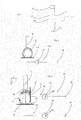
- FIG. 3 shows a rough schematic representation of a device for sterilizing containers in the form of a jet finger 50 which is insertable into the containers to be sterilized.
- This jet finger has a housing 6, the interior of which is acted upon by a vacuum.
- a charge carrier generating device 2 generates charge carriers and in particular electrons, and an accelerating device 4 (shown only schematically) accelerates these charge carriers in the direction of an exit window 12. It is possible for this sterilization device 1 or the jet finger 50 to still have channels for supplying cooling air to the exit window having. Alternatively, a closed liquid cooling of the exit window is possible.
- FIG. 4 shows an illustration of a measuring device according to the prior art.
- a measuring plate 132 is provided, which is arranged here below the exit window and which thus can come into contact with the charge carriers or electrons from an electron cloud, which emerge from the exit window 12.
- the reference numeral 136 refers to an ammeter which measures the current allowed by the impact of the carriers.
- Reference numeral 138 denotes a power source, and reference numeral 120 denotes the sensor device in its entirety.
- FIG. 5 shows a sensor device according to the invention. It can be seen that the sensor unit 20 according to the invention, in addition to the first sensor device 22, also has a second sensor device 24. This second sensor device 24 has here a measuring plate 34, which in the in FIG. 4 shown embodiment is perpendicular to the measuring plate or the measuring element 32. Thus, the electron beam derived from the electron cloud W is determined here at two plates arranged orthogonally to one another.
- the reference numeral d1 denotes a shortest distance between the measuring element 32 and the exit window
- the reference sign d2 denotes a shortest distance between the measuring element 34 and the exit window. It can be seen that the directions of these distances are perpendicular to each other here.
- the reference symbols X and Z denote the respective (middle) propagation directions of the charge carriers or electrons.
- Reference numerals M1 and M2 denote the values outputted from the measuring means 36 which, as mentioned above, are independent of one another and each of those in FIG Fig. 1 shown evaluation unit 25 are supplied.
- the reference numeral 38 again denotes a power source.
- the reference numeral 30 denotes a carrier to which the two measuring elements 32 and 34 are arranged.
- the carrier 30 is embodied here as an insulator, so that no electrical current flow between the two measuring elements 32 and 34 is possible and thus the two measuring devices 36 can independently measure the respective currents impinging on the charge carriers.
- the in FIG. 5 be shown placed between the inlet and the outlet of a sterilization device.
- the individual continuously radiating sterilization devices or finger emitters produce a current here in contact with the sensor unit 20. This allows in its strength by the comparison between the two measuring elements 32 and 34 a statement and also a control of the electron cloud W or the electron beam and thus the sterilization capacity.
- the invention is not limited to the beam fingers shown here, which are introduced into the interior of the containers, but can also be applied, for example, to stationarily arranged charge carrier and in particular electron guns.
Landscapes
- Physics & Mathematics (AREA)
- Engineering & Computer Science (AREA)
- General Engineering & Computer Science (AREA)
- High Energy & Nuclear Physics (AREA)
- Apparatus For Disinfection Or Sterilisation (AREA)
- Measurement Of Radiation (AREA)
- Apparatus Associated With Microorganisms And Enzymes (AREA)
Applications Claiming Priority (1)
| Application Number | Priority Date | Filing Date | Title |
|---|---|---|---|
| DE201210106379 DE102012106379A1 (de) | 2012-07-16 | 2012-07-16 | Messvorrichtung und Messverfahren für Behältnissterilisation |
Publications (3)
| Publication Number | Publication Date |
|---|---|
| EP2688073A2 true EP2688073A2 (fr) | 2014-01-22 |
| EP2688073A3 EP2688073A3 (fr) | 2015-03-18 |
| EP2688073B1 EP2688073B1 (fr) | 2018-04-04 |
Family
ID=48793051
Family Applications (1)
| Application Number | Title | Priority Date | Filing Date |
|---|---|---|---|
| EP13176622.2A Not-in-force EP2688073B1 (fr) | 2012-07-16 | 2013-07-16 | Dispositif de mesure et procédé de mesure pour la stérilisation de récipients |
Country Status (4)
| Country | Link |
|---|---|
| EP (1) | EP2688073B1 (fr) |
| JP (1) | JP6259598B2 (fr) |
| CN (1) | CN103536947B (fr) |
| DE (1) | DE102012106379A1 (fr) |
Cited By (1)
| Publication number | Priority date | Publication date | Assignee | Title |
|---|---|---|---|---|
| DE102022122422A1 (de) | 2022-09-05 | 2024-03-07 | Krones Aktiengesellschaft | Vorrichtung und Verfahren zum Desinfizieren von Behältern |
Families Citing this family (3)
| Publication number | Priority date | Publication date | Assignee | Title |
|---|---|---|---|---|
| CN105101605B (zh) | 2015-09-11 | 2017-11-24 | 中广核达胜加速器技术有限公司 | 一种自屏蔽加速器及利用该加速器的pet塑料瓶生产线 |
| JP6803735B2 (ja) * | 2016-12-07 | 2020-12-23 | 日立造船株式会社 | 内面電子線滅菌設備 |
| DE102016123965A1 (de) * | 2016-12-09 | 2018-06-14 | Krones Ag | Füllvorrichtung zum Abfüllen eines Füllprodukts in einen zu befüllenden Behälter in einer Füllproduktabfüllanlage |
Family Cites Families (14)
| Publication number | Priority date | Publication date | Assignee | Title |
|---|---|---|---|---|
| US6429444B1 (en) * | 1999-08-24 | 2002-08-06 | Steris Inc. | Real time monitoring of electron beam radiation dose |
| JP2001221897A (ja) * | 2000-02-14 | 2001-08-17 | Nissin High Voltage Co Ltd | 電子線分布測定装置 |
| JP2002006099A (ja) * | 2000-06-26 | 2002-01-09 | Mitsubishi Heavy Ind Ltd | 電子線照射方法及びその装置 |
| US6617596B1 (en) * | 2000-11-17 | 2003-09-09 | Steris Inc. | On-line measurement of absorbed electron beam dosage in irradiated product |
| JP2003153986A (ja) * | 2001-11-20 | 2003-05-27 | Mitsubishi Heavy Ind Ltd | 輸送途中物品の処理装置 |
| US6919570B2 (en) * | 2002-12-19 | 2005-07-19 | Advanced Electron Beams, Inc. | Electron beam sensor |
| US7375345B2 (en) * | 2005-10-26 | 2008-05-20 | Tetra Laval Holdings & Finance S.A. | Exposed conductor system and method for sensing an electron beam |
| DE102009018210C5 (de) * | 2009-04-21 | 2022-08-18 | Khs Gmbh | Verfahren und Vorrichtung zur Überwachung der Intensität eines Elektronenstrahles |
| US8293173B2 (en) * | 2009-04-30 | 2012-10-23 | Hitachi Zosen Corporation | Electron beam sterilization apparatus |
| US20110012030A1 (en) * | 2009-04-30 | 2011-01-20 | Michael Lawrence Bufano | Ebeam sterilization apparatus |
| CN101614770B (zh) * | 2009-07-28 | 2011-11-16 | 西安交通大学 | 一种基于电光效应的表面电荷测量系统 |
| JP5560662B2 (ja) * | 2009-10-29 | 2014-07-30 | 澁谷工業株式会社 | 電子線殺菌装置 |
| JP2011229622A (ja) * | 2010-04-26 | 2011-11-17 | Mitsubishi Heavy Industries Food & Packaging Machinery Co Ltd | 電子線殺菌装置における電子線照射エネルギー量監視システム |
| JP5621567B2 (ja) * | 2010-12-10 | 2014-11-12 | 澁谷工業株式会社 | 電子線殺菌装置 |
-
2012
- 2012-07-16 DE DE201210106379 patent/DE102012106379A1/de not_active Withdrawn
-
2013
- 2013-07-12 JP JP2013146700A patent/JP6259598B2/ja active Active
- 2013-07-16 EP EP13176622.2A patent/EP2688073B1/fr not_active Not-in-force
- 2013-07-16 CN CN201310297936.0A patent/CN103536947B/zh not_active Expired - Fee Related
Non-Patent Citations (1)
| Title |
|---|
| None |
Cited By (2)
| Publication number | Priority date | Publication date | Assignee | Title |
|---|---|---|---|---|
| DE102022122422A1 (de) | 2022-09-05 | 2024-03-07 | Krones Aktiengesellschaft | Vorrichtung und Verfahren zum Desinfizieren von Behältern |
| EP4342500A2 (fr) | 2022-09-05 | 2024-03-27 | Krones Ag | Dispositif et procédé de désinfection de récipients |
Also Published As
| Publication number | Publication date |
|---|---|
| CN103536947A (zh) | 2014-01-29 |
| CN103536947B (zh) | 2016-08-10 |
| JP2014040274A (ja) | 2014-03-06 |
| JP6259598B2 (ja) | 2018-01-10 |
| EP2688073A3 (fr) | 2015-03-18 |
| DE102012106379A1 (de) | 2014-01-30 |
| EP2688073B1 (fr) | 2018-04-04 |
Similar Documents
| Publication | Publication Date | Title |
|---|---|---|
| EP2688073B1 (fr) | Dispositif de mesure et procédé de mesure pour la stérilisation de récipients | |
| US9305742B2 (en) | Method and device for bunching a beam of charged particles | |
| DE102013005173B4 (de) | Messvorrichtung und Verfahren zur Erfassung einer Impulsverteilung geladener Teilchen | |
| DE102011004725A1 (de) | Verfahren und Vorrichtung zur Erhöhung des Durchsatzes bei Flugzeitmassenspektrometern | |
| DE102007014715A1 (de) | Bestimmung von Steuerparametern für eine Bestrahlung eines bewegten Zielvolumens in einem Körper | |
| DE102018113413A1 (de) | Zyklotron und Verfahren zu dessen Steuerung | |
| DE2644688A1 (de) | Anordnung zur strahlstrommessung von ladungstraegern | |
| EP2141512A2 (fr) | Procédé de contrôle de l'énergie d'un rayon de particules, dispositif de contrôle de l'énergie et installation correspondante | |
| EP2326389B1 (fr) | Balayage rapide d'une zone cible | |
| DE1937482B2 (de) | Mikrostrahlsonde | |
| DE102012109296A1 (de) | Verfahren zum Betrieb eines Teilchenstrahlgeräts und/oder zur Analyse eines Objekts in einem Teilchenstrahlgerät | |
| DE2411841C3 (de) | Auger-Elektronenspektrometer | |
| EP3245675A1 (fr) | Dispositif de guidage de supports de charges et leur utilisation | |
| DE102008035119B3 (de) | Vorrichtung und Verfahren zur Überprüfung der Funktionalität einer Strahlentherapiesonde sowie Strahlungsquelle und eine Strahlentherapiesonde | |
| DE2363581C2 (de) | Verfahren zur zerstörungsfreien chemischen Analyse | |
| DE69810785T2 (de) | Analyse geladener teilchen | |
| DE102017120408B4 (de) | Verfahren und Anordnung zum Ermitteln eines elektrischen Potentials und zum Ermitteln einer Verteilungsdichtefunktion eines Stromes von einem Strahl von Teilchen | |
| DE2542362C3 (de) | Ionenstreuspektroskopisches Verfahren und Vorrichtung zur Durchführung desselben | |
| DE102021121570A1 (de) | Vorrichtung, Verfahren und System zur Messung des Vakuumgrads einer Röntgenröhre | |
| EP3321716A1 (fr) | Procédé de fonctionnement d'un accélérateur linéaire et accélérateur linéaire | |
| DE102011055084B4 (de) | Messvorrichtung | |
| DE102009040007A1 (de) | MWPC Detektor mit Graphen zur Reduzierung der Penumbra in der Partikeltherapie | |
| DE10105773C1 (de) | Fouriertransformations-Massenspektrometer mit Bildladungsdetektor | |
| McCrory et al. | Longitudinal emittance from the fermilab 400 mev linac | |
| WO2020035205A1 (fr) | Ensemble et procédé pour détecter une valeur de mesure sur la base de l'holographie électronique |
Legal Events
| Date | Code | Title | Description |
|---|---|---|---|
| PUAI | Public reference made under article 153(3) epc to a published international application that has entered the european phase |
Free format text: ORIGINAL CODE: 0009012 |
|
| AK | Designated contracting states |
Kind code of ref document: A2 Designated state(s): AL AT BE BG CH CY CZ DE DK EE ES FI FR GB GR HR HU IE IS IT LI LT LU LV MC MK MT NL NO PL PT RO RS SE SI SK SM TR |
|
| AX | Request for extension of the european patent |
Extension state: BA ME |
|
| PUAL | Search report despatched |
Free format text: ORIGINAL CODE: 0009013 |
|
| AK | Designated contracting states |
Kind code of ref document: A3 Designated state(s): AL AT BE BG CH CY CZ DE DK EE ES FI FR GB GR HR HU IE IS IT LI LT LU LV MC MK MT NL NO PL PT RO RS SE SI SK SM TR |
|
| AX | Request for extension of the european patent |
Extension state: BA ME |
|
| RIC1 | Information provided on ipc code assigned before grant |
Ipc: H01J 37/244 20060101ALI20150206BHEP Ipc: G21K 5/00 20060101AFI20150206BHEP |
|
| 17P | Request for examination filed |
Effective date: 20150825 |
|
| RBV | Designated contracting states (corrected) |
Designated state(s): AL AT BE BG CH CY CZ DE DK EE ES FI FR GB GR HR HU IE IS IT LI LT LU LV MC MK MT NL NO PL PT RO RS SE SI SK SM TR |
|
| 17Q | First examination report despatched |
Effective date: 20161115 |
|
| GRAP | Despatch of communication of intention to grant a patent |
Free format text: ORIGINAL CODE: EPIDOSNIGR1 |
|
| INTG | Intention to grant announced |
Effective date: 20171013 |
|
| GRAJ | Information related to disapproval of communication of intention to grant by the applicant or resumption of examination proceedings by the epo deleted |
Free format text: ORIGINAL CODE: EPIDOSDIGR1 |
|
| GRAS | Grant fee paid |
Free format text: ORIGINAL CODE: EPIDOSNIGR3 |
|
| GRAP | Despatch of communication of intention to grant a patent |
Free format text: ORIGINAL CODE: EPIDOSNIGR1 |
|
| INTC | Intention to grant announced (deleted) | ||
| GRAA | (expected) grant |
Free format text: ORIGINAL CODE: 0009210 |
|
| INTG | Intention to grant announced |
Effective date: 20180222 |
|
| AK | Designated contracting states |
Kind code of ref document: B1 Designated state(s): AL AT BE BG CH CY CZ DE DK EE ES FI FR GB GR HR HU IE IS IT LI LT LU LV MC MK MT NL NO PL PT RO RS SE SI SK SM TR |
|
| REG | Reference to a national code |
Ref country code: GB Ref legal event code: FG4D Free format text: NOT ENGLISH |
|
| REG | Reference to a national code |
Ref country code: CH Ref legal event code: EP |
|
| REG | Reference to a national code |
Ref country code: AT Ref legal event code: REF Ref document number: 986422 Country of ref document: AT Kind code of ref document: T Effective date: 20180415 |
|
| REG | Reference to a national code |
Ref country code: DE Ref legal event code: R096 Ref document number: 502013009821 Country of ref document: DE |
|
| REG | Reference to a national code |
Ref country code: IE Ref legal event code: FG4D Free format text: LANGUAGE OF EP DOCUMENT: GERMAN |
|
| REG | Reference to a national code |
Ref country code: FR Ref legal event code: PLFP Year of fee payment: 6 |
|
| REG | Reference to a national code |
Ref country code: NL Ref legal event code: MP Effective date: 20180404 |
|
| REG | Reference to a national code |
Ref country code: LT Ref legal event code: MG4D |
|
| PG25 | Lapsed in a contracting state [announced via postgrant information from national office to epo] |
Ref country code: NL Free format text: LAPSE BECAUSE OF FAILURE TO SUBMIT A TRANSLATION OF THE DESCRIPTION OR TO PAY THE FEE WITHIN THE PRESCRIBED TIME-LIMIT Effective date: 20180404 |
|
| PG25 | Lapsed in a contracting state [announced via postgrant information from national office to epo] |
Ref country code: LT Free format text: LAPSE BECAUSE OF FAILURE TO SUBMIT A TRANSLATION OF THE DESCRIPTION OR TO PAY THE FEE WITHIN THE PRESCRIBED TIME-LIMIT Effective date: 20180404 Ref country code: NO Free format text: LAPSE BECAUSE OF FAILURE TO SUBMIT A TRANSLATION OF THE DESCRIPTION OR TO PAY THE FEE WITHIN THE PRESCRIBED TIME-LIMIT Effective date: 20180704 Ref country code: FI Free format text: LAPSE BECAUSE OF FAILURE TO SUBMIT A TRANSLATION OF THE DESCRIPTION OR TO PAY THE FEE WITHIN THE PRESCRIBED TIME-LIMIT Effective date: 20180404 Ref country code: BG Free format text: LAPSE BECAUSE OF FAILURE TO SUBMIT A TRANSLATION OF THE DESCRIPTION OR TO PAY THE FEE WITHIN THE PRESCRIBED TIME-LIMIT Effective date: 20180704 Ref country code: ES Free format text: LAPSE BECAUSE OF FAILURE TO SUBMIT A TRANSLATION OF THE DESCRIPTION OR TO PAY THE FEE WITHIN THE PRESCRIBED TIME-LIMIT Effective date: 20180404 Ref country code: AL Free format text: LAPSE BECAUSE OF FAILURE TO SUBMIT A TRANSLATION OF THE DESCRIPTION OR TO PAY THE FEE WITHIN THE PRESCRIBED TIME-LIMIT Effective date: 20180404 Ref country code: SE Free format text: LAPSE BECAUSE OF FAILURE TO SUBMIT A TRANSLATION OF THE DESCRIPTION OR TO PAY THE FEE WITHIN THE PRESCRIBED TIME-LIMIT Effective date: 20180404 Ref country code: PL Free format text: LAPSE BECAUSE OF FAILURE TO SUBMIT A TRANSLATION OF THE DESCRIPTION OR TO PAY THE FEE WITHIN THE PRESCRIBED TIME-LIMIT Effective date: 20180404 |
|
| PG25 | Lapsed in a contracting state [announced via postgrant information from national office to epo] |
Ref country code: LV Free format text: LAPSE BECAUSE OF FAILURE TO SUBMIT A TRANSLATION OF THE DESCRIPTION OR TO PAY THE FEE WITHIN THE PRESCRIBED TIME-LIMIT Effective date: 20180404 Ref country code: GR Free format text: LAPSE BECAUSE OF FAILURE TO SUBMIT A TRANSLATION OF THE DESCRIPTION OR TO PAY THE FEE WITHIN THE PRESCRIBED TIME-LIMIT Effective date: 20180705 Ref country code: HR Free format text: LAPSE BECAUSE OF FAILURE TO SUBMIT A TRANSLATION OF THE DESCRIPTION OR TO PAY THE FEE WITHIN THE PRESCRIBED TIME-LIMIT Effective date: 20180404 Ref country code: RS Free format text: LAPSE BECAUSE OF FAILURE TO SUBMIT A TRANSLATION OF THE DESCRIPTION OR TO PAY THE FEE WITHIN THE PRESCRIBED TIME-LIMIT Effective date: 20180404 |
|
| PG25 | Lapsed in a contracting state [announced via postgrant information from national office to epo] |
Ref country code: PT Free format text: LAPSE BECAUSE OF FAILURE TO SUBMIT A TRANSLATION OF THE DESCRIPTION OR TO PAY THE FEE WITHIN THE PRESCRIBED TIME-LIMIT Effective date: 20180806 |
|
| REG | Reference to a national code |
Ref country code: DE Ref legal event code: R097 Ref document number: 502013009821 Country of ref document: DE |
|
| PG25 | Lapsed in a contracting state [announced via postgrant information from national office to epo] |
Ref country code: DK Free format text: LAPSE BECAUSE OF FAILURE TO SUBMIT A TRANSLATION OF THE DESCRIPTION OR TO PAY THE FEE WITHIN THE PRESCRIBED TIME-LIMIT Effective date: 20180404 Ref country code: EE Free format text: LAPSE BECAUSE OF FAILURE TO SUBMIT A TRANSLATION OF THE DESCRIPTION OR TO PAY THE FEE WITHIN THE PRESCRIBED TIME-LIMIT Effective date: 20180404 Ref country code: CZ Free format text: LAPSE BECAUSE OF FAILURE TO SUBMIT A TRANSLATION OF THE DESCRIPTION OR TO PAY THE FEE WITHIN THE PRESCRIBED TIME-LIMIT Effective date: 20180404 Ref country code: RO Free format text: LAPSE BECAUSE OF FAILURE TO SUBMIT A TRANSLATION OF THE DESCRIPTION OR TO PAY THE FEE WITHIN THE PRESCRIBED TIME-LIMIT Effective date: 20180404 Ref country code: SK Free format text: LAPSE BECAUSE OF FAILURE TO SUBMIT A TRANSLATION OF THE DESCRIPTION OR TO PAY THE FEE WITHIN THE PRESCRIBED TIME-LIMIT Effective date: 20180404 |
|
| PLBE | No opposition filed within time limit |
Free format text: ORIGINAL CODE: 0009261 |
|
| STAA | Information on the status of an ep patent application or granted ep patent |
Free format text: STATUS: NO OPPOSITION FILED WITHIN TIME LIMIT |
|
| PG25 | Lapsed in a contracting state [announced via postgrant information from national office to epo] |
Ref country code: SM Free format text: LAPSE BECAUSE OF FAILURE TO SUBMIT A TRANSLATION OF THE DESCRIPTION OR TO PAY THE FEE WITHIN THE PRESCRIBED TIME-LIMIT Effective date: 20180404 |
|
| REG | Reference to a national code |
Ref country code: CH Ref legal event code: PL |
|
| 26N | No opposition filed |
Effective date: 20190107 |
|
| GBPC | Gb: european patent ceased through non-payment of renewal fee |
Effective date: 20180716 |
|
| PG25 | Lapsed in a contracting state [announced via postgrant information from national office to epo] |
Ref country code: MC Free format text: LAPSE BECAUSE OF FAILURE TO SUBMIT A TRANSLATION OF THE DESCRIPTION OR TO PAY THE FEE WITHIN THE PRESCRIBED TIME-LIMIT Effective date: 20180404 Ref country code: LU Free format text: LAPSE BECAUSE OF NON-PAYMENT OF DUE FEES Effective date: 20180716 |
|
| REG | Reference to a national code |
Ref country code: BE Ref legal event code: MM Effective date: 20180731 |
|
| REG | Reference to a national code |
Ref country code: IE Ref legal event code: MM4A |
|
| PG25 | Lapsed in a contracting state [announced via postgrant information from national office to epo] |
Ref country code: LI Free format text: LAPSE BECAUSE OF NON-PAYMENT OF DUE FEES Effective date: 20180731 Ref country code: IE Free format text: LAPSE BECAUSE OF NON-PAYMENT OF DUE FEES Effective date: 20180716 Ref country code: GB Free format text: LAPSE BECAUSE OF NON-PAYMENT OF DUE FEES Effective date: 20180716 Ref country code: CH Free format text: LAPSE BECAUSE OF NON-PAYMENT OF DUE FEES Effective date: 20180731 |
|
| PG25 | Lapsed in a contracting state [announced via postgrant information from national office to epo] |
Ref country code: SI Free format text: LAPSE BECAUSE OF FAILURE TO SUBMIT A TRANSLATION OF THE DESCRIPTION OR TO PAY THE FEE WITHIN THE PRESCRIBED TIME-LIMIT Effective date: 20180404 Ref country code: BE Free format text: LAPSE BECAUSE OF NON-PAYMENT OF DUE FEES Effective date: 20180731 |
|
| REG | Reference to a national code |
Ref country code: AT Ref legal event code: MM01 Ref document number: 986422 Country of ref document: AT Kind code of ref document: T Effective date: 20180716 |
|
| PG25 | Lapsed in a contracting state [announced via postgrant information from national office to epo] |
Ref country code: AT Free format text: LAPSE BECAUSE OF NON-PAYMENT OF DUE FEES Effective date: 20180716 |
|
| PG25 | Lapsed in a contracting state [announced via postgrant information from national office to epo] |
Ref country code: MT Free format text: LAPSE BECAUSE OF FAILURE TO SUBMIT A TRANSLATION OF THE DESCRIPTION OR TO PAY THE FEE WITHIN THE PRESCRIBED TIME-LIMIT Effective date: 20180404 |
|
| PG25 | Lapsed in a contracting state [announced via postgrant information from national office to epo] |
Ref country code: TR Free format text: LAPSE BECAUSE OF FAILURE TO SUBMIT A TRANSLATION OF THE DESCRIPTION OR TO PAY THE FEE WITHIN THE PRESCRIBED TIME-LIMIT Effective date: 20180404 |
|
| PG25 | Lapsed in a contracting state [announced via postgrant information from national office to epo] |
Ref country code: HU Free format text: LAPSE BECAUSE OF FAILURE TO SUBMIT A TRANSLATION OF THE DESCRIPTION OR TO PAY THE FEE WITHIN THE PRESCRIBED TIME-LIMIT; INVALID AB INITIO Effective date: 20130716 |
|
| PG25 | Lapsed in a contracting state [announced via postgrant information from national office to epo] |
Ref country code: MK Free format text: LAPSE BECAUSE OF NON-PAYMENT OF DUE FEES Effective date: 20180404 Ref country code: CY Free format text: LAPSE BECAUSE OF FAILURE TO SUBMIT A TRANSLATION OF THE DESCRIPTION OR TO PAY THE FEE WITHIN THE PRESCRIBED TIME-LIMIT Effective date: 20180404 |
|
| PG25 | Lapsed in a contracting state [announced via postgrant information from national office to epo] |
Ref country code: IS Free format text: LAPSE BECAUSE OF FAILURE TO SUBMIT A TRANSLATION OF THE DESCRIPTION OR TO PAY THE FEE WITHIN THE PRESCRIBED TIME-LIMIT Effective date: 20180804 |
|
| P01 | Opt-out of the competence of the unified patent court (upc) registered |
Effective date: 20230523 |
|
| PGFP | Annual fee paid to national office [announced via postgrant information from national office to epo] |
Ref country code: FR Payment date: 20240611 Year of fee payment: 12 |
|
| PGFP | Annual fee paid to national office [announced via postgrant information from national office to epo] |
Ref country code: IT Payment date: 20240612 Year of fee payment: 12 |
|
| PGFP | Annual fee paid to national office [announced via postgrant information from national office to epo] |
Ref country code: DE Payment date: 20240604 Year of fee payment: 12 |
|
| REG | Reference to a national code |
Ref country code: DE Ref legal event code: R119 Ref document number: 502013009821 Country of ref document: DE |
|
| PG25 | Lapsed in a contracting state [announced via postgrant information from national office to epo] |
Ref country code: DE Free format text: LAPSE BECAUSE OF NON-PAYMENT OF DUE FEES Effective date: 20260203 |
|
| PG25 | Lapsed in a contracting state [announced via postgrant information from national office to epo] |
Ref country code: FR Free format text: LAPSE BECAUSE OF NON-PAYMENT OF DUE FEES Effective date: 20250731 |
|
| PG25 | Lapsed in a contracting state [announced via postgrant information from national office to epo] |
Ref country code: IT Free format text: LAPSE BECAUSE OF NON-PAYMENT OF DUE FEES Effective date: 20250716 |