EP2688152A1 - Connecteur de dispositif électronique, fiche de dispositif électronique, et structure étanche à l'eau de dispositif électronique - Google Patents
Connecteur de dispositif électronique, fiche de dispositif électronique, et structure étanche à l'eau de dispositif électronique Download PDFInfo
- Publication number
- EP2688152A1 EP2688152A1 EP12757456.4A EP12757456A EP2688152A1 EP 2688152 A1 EP2688152 A1 EP 2688152A1 EP 12757456 A EP12757456 A EP 12757456A EP 2688152 A1 EP2688152 A1 EP 2688152A1
- Authority
- EP
- European Patent Office
- Prior art keywords
- connector
- electronic device
- case
- sealing material
- convex stripe
- Prior art date
- Legal status (The legal status is an assumption and is not a legal conclusion. Google has not performed a legal analysis and makes no representation as to the accuracy of the status listed.)
- Granted
Links
Images





Classifications
-
- H—ELECTRICITY
- H04—ELECTRIC COMMUNICATION TECHNIQUE
- H04M—TELEPHONIC COMMUNICATION
- H04M1/00—Substation equipment, e.g. for use by subscribers
- H04M1/02—Constructional features of telephone sets
-
- H—ELECTRICITY
- H01—ELECTRIC ELEMENTS
- H01R—ELECTRICALLY-CONDUCTIVE CONNECTIONS; STRUCTURAL ASSOCIATIONS OF A PLURALITY OF MUTUALLY-INSULATED ELECTRICAL CONNECTING ELEMENTS; COUPLING DEVICES; CURRENT COLLECTORS
- H01R13/00—Details of coupling devices of the kinds covered by groups H01R12/70 or H01R24/00 - H01R33/00
- H01R13/46—Bases; Cases
- H01R13/52—Dustproof, splashproof, drip-proof, waterproof, or flameproof cases
-
- H—ELECTRICITY
- H01—ELECTRIC ELEMENTS
- H01R—ELECTRICALLY-CONDUCTIVE CONNECTIONS; STRUCTURAL ASSOCIATIONS OF A PLURALITY OF MUTUALLY-INSULATED ELECTRICAL CONNECTING ELEMENTS; COUPLING DEVICES; CURRENT COLLECTORS
- H01R13/00—Details of coupling devices of the kinds covered by groups H01R12/70 or H01R24/00 - H01R33/00
- H01R13/46—Bases; Cases
- H01R13/52—Dustproof, splashproof, drip-proof, waterproof, or flameproof cases
- H01R13/5202—Sealing means between parts of housing or between housing part and a wall, e.g. sealing rings
-
- H—ELECTRICITY
- H01—ELECTRIC ELEMENTS
- H01R—ELECTRICALLY-CONDUCTIVE CONNECTIONS; STRUCTURAL ASSOCIATIONS OF A PLURALITY OF MUTUALLY-INSULATED ELECTRICAL CONNECTING ELEMENTS; COUPLING DEVICES; CURRENT COLLECTORS
- H01R13/00—Details of coupling devices of the kinds covered by groups H01R12/70 or H01R24/00 - H01R33/00
- H01R13/46—Bases; Cases
- H01R13/52—Dustproof, splashproof, drip-proof, waterproof, or flameproof cases
- H01R13/5219—Sealing means between coupling parts, e.g. interfacial seal
-
- H—ELECTRICITY
- H04—ELECTRIC COMMUNICATION TECHNIQUE
- H04M—TELEPHONIC COMMUNICATION
- H04M1/00—Substation equipment, e.g. for use by subscribers
- H04M1/02—Constructional features of telephone sets
- H04M1/0202—Portable telephone sets, e.g. cordless phones, mobile phones or bar type handsets
- H04M1/026—Details of the structure or mounting of specific components
- H04M1/0274—Details of the structure or mounting of specific components for an electrical connector module
-
- H—ELECTRICITY
- H01—ELECTRIC ELEMENTS
- H01R—ELECTRICALLY-CONDUCTIVE CONNECTIONS; STRUCTURAL ASSOCIATIONS OF A PLURALITY OF MUTUALLY-INSULATED ELECTRICAL CONNECTING ELEMENTS; COUPLING DEVICES; CURRENT COLLECTORS
- H01R13/00—Details of coupling devices of the kinds covered by groups H01R12/70 or H01R24/00 - H01R33/00
- H01R13/46—Bases; Cases
- H01R13/52—Dustproof, splashproof, drip-proof, waterproof, or flameproof cases
- H01R13/5213—Covers
-
- H—ELECTRICITY
- H04—ELECTRIC COMMUNICATION TECHNIQUE
- H04M—TELEPHONIC COMMUNICATION
- H04M1/00—Substation equipment, e.g. for use by subscribers
- H04M1/02—Constructional features of telephone sets
- H04M1/18—Telephone sets specially adapted for use in ships, mines, or other places exposed to adverse environment
Definitions
- the present invention relates to a connector of a waterproof electronic device such as charging connector for mobile phone, a plug of an electronic device and a waterproof structure of an electronic device.
- a cover 210 in this waterproof structure is as shown in Fig. 9(a) and includes a cover main body 211 of a rectangular shape in the front view, and a substantially elliptical projection 212 arranged to protrude to an insertion side from the cover main body 211, wherein a recessed groove 213 is formed in the outer periphery of the projection 212.
- An O-ring 214 is fitted and installed along the recessed groove 213.
- a housing of an electronic device is also provided with a bottomed opening 220 of a substantially elliptical cylindrical shape and a hole 222 is formed in a rear wall 221 of the opening 220, as shown in Fig. 9(b) .
- a connector 230 is placed to face the rear side of the opening 220 so that a tip end of the connector is placed in the hole 222.
- the connector 230 is connected to a circuit board 233 by a shell 231 and a contact terminal 232 thereof.
- the cover 210 is fitted in the opening 220 in such a manner that the O-ring 214 is pressed against and brought into contact with an inner circumferential surface 223 of the opening 120 throughout the entire circumference, whereby preventing water from intruding into the inside beyond an area in which the O-ring 214 and the inner circumferential surface 223 are in contact with each other.
- Patent Document 1 a similar structure is disclosed in Patent Document 1.
- Patent Document 1 Japanese Unexamined Patent Application Publication No. 2009-111720
- the cover 210 in the above waterproof structure is a so-called four-layer structure consisting of the cover main body 211, a portion of the projection 212 closer to the cover main body 111 than the recessed groove 213, the O-ring 214, and a portion of the projection 212 closer to the insertion side than the recessed groove 213, and has a thickness t1' that is as thick as about 3 mm. Accordingly, a space for installing the opening 220 and the connector 230 requires a long depth t2' of, for example, about 8.5 mm and occupies a large area in a housing of an electronic device. Furthermore, due to the necessity of providing the opening 220 for accommodating this large cover 210, the electronic device results in having a thick housing.
- the connector 230 needs to be placed in a deeper position than the thick cover 210, a remaining space in the housing of the electronic device is reduced and restriction is imposed on designing the layout of a circuit board and wiring therefor, increasing the number of circuits to be mounted and enlarging the size of a battery, which is problematic.
- the cover 210 in which the O-ring 214 is fitted in the recessed groove 213 needs to be large and requires a step of fitting the O-ring 214 so that a problem arises with increased manufacturing costs and reduction of the yield due to an increase in the number of parts.
- the present invention was proposed to solve the above problems and aims at providing a connector of an electronic device, a plug of an electronic device and a waterproof structure of an electronic device in which a remaining space in the housing of an electronic device can be enlarged, the degree of freedom in designing the layout of a circuit board and wiring therefor can be improved, the number of circuits to be mounted can be increased, a battery can be made larger, and a housing of an electronic device can be made thinner and more compact.
- Another object of the present invention is to provide a connector of an electronic device, a plug of an electronic device and a waterproof structure of an electronic device in which manufacturing costs of a cover can be reduced with an increased yield.
- a connector of an electronic device comprises a substantially cylindrical case, connector-side terminals inserted into the case, and a sealing material that is arranged in the vicinity of the end of the case on a plug insertion side so as to protrude to the plug insertion side, and that is formed around an outer circumference of the case, wherein a first convex stripe is formed along an inner circumference of the protruding section of the sealing material, and the first convex stripe is formed so as to be pressed against and brought into contact with an outer circumferential surface of a part of a cover to be inserted.
- waterproof sealing is applied by bringing the first convex stripe of the sealing material, which protrudes to the plug insertion side in the outer circumference of the case, into contact with a part of the cover and therefore the cover is made thinner, whereby allowing installation of the connector in a position closer to an opening edge of the housing of an electronic device. Accordingly, it is possible to enlarge a remaining space in the housing of an electronic device, to improve the degree of freedom in designing the layout of a circuit board and wiring therefor, to increase the number of circuits to be mounted, and to make a battery larger. It is also possible to provide a cover in a simplified structure and make the housing of an electronic device thinner and more compact. Manufacturing costs of the cover can also be reduced with an increased yield. In addition, the sealing material can be visually observed by leaving the cover open, so that it is possible to attract user's attention to the characteristics of the waterproof structure.
- the connector of an electronic device is characterized in that the first convex stripe is formed so as to be circumferentially pressed against and brought into contact with both an outer circumferential surface of a part of the plug and an outer circumferential surface of a part of the inserted cover.
- the connector of an electronic device is characterized in that the first convex stripe is formed into a substantially dorsal fin shape in the cross sectional view with a front side thereof disposed to the plug insertion side.
- the first convex stripe which often is rubbed against a part of the cover and a part of a plug, can be brought into contact with them in a form of falling down to a direction opposite to the plug insertion side, whereby making it possible to prevent abrasion of the first convex stripe and enhance durability thereof.
- the waterproof structure provided by the cover of the above conventional example is accompanied by accelerated abrasion of the O-ring resulting from opening/closing operation and inferior durability.
- the connector of an electronic device is characterized in that a second convex stripe is formed along the outer circumference of the sealing material and the second convex stripe is formed so as to be circumferentially pressed against and brought into contact with an inner circumferential surface of a mounting part of the housing of an electronic device.
- waterproof sealing is applied by bringing the inner circumferential surface of the mounting part of the housing of an electronic device and the second convex stripe into contact with each other, whereby allowing prevention of water intrusion from a space between the housing and the sealing material into the housing. Also, owing to the sealing material placed in the vicinity of the end of a connector case, collective waterproof measures can be taken at the same time against a water intruding path from the cover into the connector and against a water intruding path from a space between the housing of an electronic device and the connector into the housing.
- the connector of an electronic device is characterized in that the second convex stripe is formed in a position drawn to a direction opposite to the plug insertion side more than the first convex stripe.
- an insertion distance of the connector that is inserted while the inner circumferential surface of the mounting part is pressed by the second convex stripe can be made shorter, which makes it easier to insert the connector.
- the connector of an electronic device is characterized in that a convex that is shorter than the second convex stripe is formed along the outer circumference of the sealing material in a position drawn to the plug insertion side more than the second convex stripe.
- the convex is used to function as a relief to come in contact with the inner circumferential surface of the mounting part when the sealing material attached to the case is inserted into the mounting part, and a clearance is provided by making a basic outer diameter of the sealing material attached to the case slightly smaller than an inner diameter of the inner circumferential surface of the mounting part of the housing of an electronic device, so that the sealing material attached to the case can be inserted into the mounting part in a simple manner and stabilized in a normal position without being distorted.
- the connector of an electronic device according to the present invention is characterized in that the case is made of a resin and the sealing material is made of a softer resin than the resin of the case.
- the shape of the case can be maintained and workability is improved in installation operation or other operation by using, for example, a rigid resin for the case and a softer resin than the resin of the case for the sealing material, while making it possible to prevent water intrusion from a space between the housing of an electronic device and the sealing material more reliably owing to elasticity of the sealing material.
- the connector of an electronic device according to the present invention is characterized in that the sealing material made of the above resin is welded to the case made of the above resin.
- the connector of an electronic device according to the present invention is characterized in that another sealing material is provided in an inner area of the case.
- a plug of an electronic device is characterized in that the plug is inserted into a connector comprising: a substantially cylindrical case; connector-side terminals introduced into the case; a sealing material that is formed in the vicinity of the end of the case on a plug insertion side so as to protrude to the plug insertion side, and that is formed around the outer circumference of the case; and a first convex stripe formed along the inner circumference of the protruding section of the sealing material, wherein the plug is inserted in such a manner that the first convex stripe is circumferentially pressed against and brought into contact with an outer circumferential surface of a part of the plug.
- waterproof sealing is applied by bringing the first convex stripe of the sealing material protruding to the plug insertion side on the outer circumference of the case into contact with a part of the plug so that a waterproof measure can be taken when the plug is inserted.
- This structure further allows installation of the connector in a position closer to an opening edge of the housing of an electronic device, whereby making it possible to enlarge a remaining space in the housing of an electronic device, improve the degree of freedom in designing the layout of a circuit board and wiring therefor, increasing the number of circuits to be mounted and making a battery larger.
- the housing of an electronic device can also be made thinner and more compact, while reducing manufacturing costs of the cover with an improved yield.
- a waterproof structure of an electronic device is provided with a connector made of a substantially cylindrical case, connector-side terminals introduced into the case, and a sealing material that is formed in the vicinity of the end of the case on a plug insertion side so as to protrude to a plug insertion side, and that is formed around the outer circumference of the case, and a cover to be partially inserted into the connector, wherein a first convex stripe is formed along the inner circumference of the protruding section of the sealing material and the first convex stripe is circumferentially pressed against and brought into contact with an outer circumferential surface of a part of the cover to be inserted into the connector.
- the cover owing to waterproof sealing applied by bringing the sealing material protruding to the plug insertion side on the outer circumference of the case into contact with a part of the cover, the cover can be thin and the connector can be arranged in a position closer to an opening edge of the housing of an electronic device. Accordingly, it is possible to enlarge a remaining space in the housing of an electronic device, to improve the degree of freedom in designing the layout of a circuit board and wiring therefor, to increase the number of circuits to be mounted, and to make a battery larger.
- the cover can also be provided in a simplified structure and the housing of an electronic device can be made thinner and more compact, while reducing manufacturing costs of the cover with an improved yield. It is also possible to draw user's attention to the characteristics of the waterproof structure because the sealing material can be visually observed by leaving the cover open.
- the cover can be thin and the connector can be arranged in a position closer to an opening edge of the housing of an electronic device.
- the cover can also be provided in a simplified structure and the housing of an electronic device can be made thinner and more compact, while reducing manufacturing costs of the cover with an improved yield. It is also possible to attract user's attention to the characteristics of the waterproof structure to the use because the sealing material can be visually observed by leaving the cover open. An internal circuit can also be prevented from being damaged due to water intrusion into the connector.
- a connector 1 of an electronic device is used as a charging connector for mobile phone or other connectors and accommodated in a housing 10 of an electronic device such as mobile phone, as shown in Fig. 1 to Fig. 3 .
- the housing 10 is composed of a main body 11 and a cover body 12.
- the main body 11 is formed into a box shape with an opened upper surface and a front surface 111 thereof is provided with a recess 112 in the middle in which an opening 113 is created at the center.
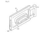
- the recess 112 is provided with a cover 13 through engagement of a hinge 131 and an engaging part 114 and the recess 112 is closed in a normal state by the cover 13 that is allowed to open/close by the hinge 31 (see Fig. 5 ).
- the cover 13 and a projection 132 thereof are preferably made of, for example, hard elastomer or hard resin produced by placing polycarbonate on the outer surface of hard elastomer.
- the periphery of the opening 113 serves as a cylindrical mounting part 115 that is substantially square in the front view and a sealing material 6 to be described later is brought into contact with an inner circumferential surface 116 of the mounting part 115 so as to be pressed thereagainst, whereby the connector 1 is attached to the mounting part 115.
- the cover body 12 that is formed into a substantially rectangular plate shape in the plan view is also placed on the open side of the main body 11 and fixed to the main body 11.
- the connector 1 is as shown in Fig. 3 and Fig. 4 and provided with a substantially cylindrical case 2, contact terminals 3 and ground terminals 4 that are introduced into the case 2 and serve as terminals of the connector, a metal shell 5 that is fitted inside the case 2 and made conductive with the ground terminals 4, and the sealing material 6 that is formed in the vicinity of the end of the case 2 on a plug insertion side so as to protrude to the plug insertion side, and that is formed around the outer circumference of the case 2.
- the case 2 which is substantially rectangular in the front view and formed into a substantially square cylindrical shape, is made of a hard resin such as polycarbonate resin or ABS resin or the like.
- a support part 21 is formed in a wall shape so as to substantially close the case 2.
- the support part 21 is formed with through holes 22 and the contact terminals 3 are placed and introduced into the case 2 by being inserted into the through holes 22 and supported by the support part 21.
- the contact terminals 3 are led from the inner side of the case 2 and electrically connected to a circuit board 8 that is placed in the housing 10.
- the support part 21 is also formed with another through hole not shown and the ground terminal 4 is placed by being inserted thereinto.
- the ground terminals 4 are introduced into the case 2, electrically connected to the conductive shell 5 that is mounted inside the case 2 and described later, lead from an inner side of the case 2 and electrically connected to the circuit board 8.
- a set of the contact terminals 3 and the ground terminals 4 or a set of the contact terminals 3, the ground terminals 4 and the shell 5 corresponds to a connector-side terminal to be introduced into the case 2.
- a flange 23 is formed circumferentially to protrude outward on the outer circumference of the case 2 at a substantially center in the axial direction and an engaging recess 24 is formed as a groove along an outer circumferential surface of the flange 23 on the plug insertion side.
- An inner end surface of the sealing material 6 to be described later comes in contact with a surface of the flange 23 on the plug insertion side and an inner end section of the sealing material 6 is engaged with the engaging recess 24.
- the engaging recess 24 can also be formed in a punctiform manner with predetermined intervals interposed along the outer circumferential surface of the case 2 and there can also be a structure without providing the engaging recess 24.
- the shell 5 is substantially rectangular in the front view and formed into a substantially quadrangular cylindrical shape with an outer diameter set to be the same as or slightly smaller than an inner diameter of the case 2, and mounted inside the case 2.
- a fitting groove 25 is formed on the periphery of the support part 21 on the plug insertion side and the shell 5 is fitted and attached to the fitting groove 25 by an inner end section thereof.
- the sealing material 6 is made of a softer resin than a resin of the case 2 and examples of the soft resin include, for example, elastomer such as silicone elastomer or the like.
- the sealing material 6 is formed to protrude from the end of the case 2 to the plug insertion side and formed around the outer circumference of the case 2 so that an engaging part 61 formed to protrude inward at the end of the sealing material 6 on the inner side is engaged with the engaging recess 24.
- the sealing material 6 is also formed with an overhang 62 that protrudes outward at an inner end thereof so that the connector 1 is attached to the mounting part 115 by bringing the overhang 62 into contact with an end surface of the mounting part 115.
- the sealing material 6 is welded to the case 2 and dissolved to be integrated with the case 2 in boundary surfaces thereof on an outer circumferential surface, the engaging recess 24 and a surface of the flange 23 of the case 2 on the plug insertion side. Note that the sealing material 6 can also be arranged in other methods such as simply fitting it to the case 2 without welding or attaching it thereto by adhesive.
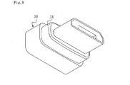
- a protruding section of the sealing material 6 on the plug insertion side is formed as a first convex stripe 63 so as to protrude inward along the inner circumference thereof, wherein the first convex stripe 63 is formed so as to be circumferentially pressed against and brought into contact with an outer circumferential surface of the projection 132 that is a part of the cover 13 to be inserted, and an outer circumferential surface of a contact 31 that is a part of a plug 30 to be inserted (see Fig. 3 and Fig. 7 ).
- the first convex stripe 63 is formed into a substantially dorsal fin shape in the cross sectional view a with a front side thereof disposed to the plug insertion side and the first convex stripe 63, which is frequently rubbed against the projection 132 of the cover 13 and the contact 31 of the plug 30 when the projection 132 and the contact 31 are inserted thereinto, can be brought into contact therewith in a form of falling down to a direction opposite to the plug insertion side, so that the first convex stripe 63 is configured to enable prevention of abrasion and enhancement of durability.
- a second convex stripe 64 is formed to protrude outward along the outer circumference of the sealing material 6 and the second convex stripe 64 is formed so as to be circumferentially pressed against and brought into contact with the inner circumferential surface 116 of the mounting part 115 of the housing 10 of an electronic device.
- the second convex stripe 64 of this example is formed into a substantially chevron shape in the cross sectional view so as to be easily inserted into the mounting part 115 and realize high stability after insertion, it can also be formed into other shapes such as substantially semicircular shape in the cross sectional view.
- a convex 65 that is shorter than the second convex stripe 64 is formed to protrude outward along the outer circumference of the sealing material 6.
- An outer diameter of an outer circumferential surface 66 of the sealing material 6 is formed to be slightly smaller than an inner diameter of the inner circumferential surface 116 of the mounting part 115 in the housing 10 of an electronic device, wherein the second convex stripe 64 comes in contact with the inner circumferential surface 116 of the mounting part and the convex 65 also comes in contact with the inner circumferential surface 116 of the mounting part 115.
- the convex 65 that is formed into a circumferential convex stripe can also be configured in a punctiform manner with predetermined intervals interposed circumferentially.
- Another sealing material 7 such as adhesive is also filled in a space formed by an inner peripheral wall of the case 2 and the support part 21 in order to more reliably prevent water intrusion into the circuit board 8 that is provided behind the connector 1. It is also possible to provide a structure without arrangement of another sealing material 7 by, for example, insert-molding components such as the contact terminals 3, the ground terminals 4 and the like to the case 2.
- the connector 1 constitutes a connection device by being mounted inside the housing 10 of an electronic device and the connector 1 is arranged in such that the sealing material 6 is inserted into the mounting part 115, wherein the second convex stripe 64 and the convex 65 are pressed against and brought into contact with the inner circumferential surface 116 of the mounting part 115. Owing to waterproof sealing applied by bringing the inner circumferential surface 116 of the mounting part 115 of the housing 10 and the second convex stripe 64 into contact with each other, water intrusion from a space between the housing 10 and the sealing material 6 into the housing 10 is prevented.
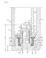
- the first convex stripe 63 of the sealing material 6 is circumferentially pressed against and brought into contact with an outer circumferential surface of the projection 132 of the cover 13 as shown in Fig. 3 in order to prevent water intrusion into the connector 1 by sealing with the use of the projection 132 of the cover 13 and the first convex stripe 63 of the sealing material 6.
- the first convex stripe 63 that is in contact with the outer circumferential surface of the projection 132 is in a form of falling down to a direction opposite to the insertion side of the projection 132 and it returns to a substantially dorsal fin shape in the cross sectional view when the projection 132 is pulled out.
- a thickness t1 of the cover main body 133 of the cover 13 it is possible to set a thickness t1 of the cover main body 133 of the cover 13 to about 1.5 mm which is less than about 3 mm of the thickness t1' of the cover 210 as the above conventional example, and set a depth t2 of a portion in which the cover main body 133 and the connector 1 are installed to about 7.5 mm which is less than about 8.5 mm of the depth t2' of a portion in which the opening 220 and the connector 230 are installed. Owing to the reduction of the depth, a remaining space can be enlarged in the housing 10 of an electronic device in which components are mounted with high density.
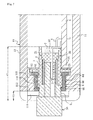
- the first convex stripe 63 of the sealing material 6 is circumferentially pressed against and brought into contact with an outer circumferential surface of the contact 31 of the plug 30 as shown in Fig. 6 to Fig. 8 , wherein water intrusion into the connector 1 is prevented by sealing between the contact 31 of the plug 30 and the first convex stripe 63 of the sealing material 6.
- the first convex stripe 63 is also in contact with an outer circumferential surface of the connector 31 in a form of falling down to a direction opposite to the plug insertion side and it returns to a substantially dorsal fin shape in the cross sectional view when the plug 30 is pulled out.
- the plug 30 or the waterproof structure of an electronic device owing to waterproof sealing applied by bringing the first convex stripe 63 of the sealing material 6 into contact with a part of the cover 13 or a part of the plug 30, the cover 13 can be thin and the connector 1 can be placed in a position closer to the opening edge of the housing 10 of an electronic device. Accordingly, a remaining space in the housing 10 of an electronic device can be enlarged, the degree of freedom in designing the layout of a circuit board and wiring therefor can be improved, the number of circuits to be mounted can be increased, and a battery can be made larger.
- the cover 13 can also provided in a simplified structure and the housing 10 of an electronic device can be made thinner and more compact, while enabling reduction of manufacturing costs of the cover 13, reduction in the number of component parts and improvement of the yield. It is also possible to attract user's attention to the characteristics of the waterproof structure because the sealing material 6 can be visually observed by leaving the cover 13 open.
- first stripe 63 a waterproof measure can be taken for both cases with the cover 13 attached and with the plug 30 inserted, so that collective waterproof measures can be taken for both cases.
- the first convex stripe 63 that is often rubbed against surfaces can also be in contact with surfaces in a form of falling down to a direction opposite to the plug insertion side, whereby making it possible to prevent abrasion of the first convex stripe 63 and enhance durability thereof.
- the second convex stripe 64 in a position drawn to a side opposite to the plug insertion side more than the first convex stripe 63, when the connector 1 is inserted from a side opposite to the plug insertion side into the mounting part 115 of the housing 10, an insertion distance of the connector 1 that is inserted while the inner circumferential surface 116 of the mounting part 115 is pressed by the second convex stripe 64 can be made shorter to make insertion of the connector 1 easier.
- the convex 65 is used to function as a relief to be in contact with the inner circumferential surface 116 of the mounting part when the sealing material 6 fitted to the case 2 is inserted into the mounting part 115, and a clearance is provided by making an outer diameter of the outer circumferential surface 66 of the sealing material 6 fitted to the case 2 slightly smaller than an inner diameter of the inner circumferential surface 116 of the mounting part 115, whereby making it possible to insert the sealing material 6 fitted to the case 2 into the mounting part 115 in a simple manner and stabilize it in a normal position without distortion.
- the invention disclosed in this specification includes, in addition to respective inventions, embodiment and configurations of respective examples, in an applicable range, a matter defined by modifying any of these partial configurations into other configurations disclosed in this specification, a matter defined by adding any of other configurations disclosed in the this specification to these partial configurations, or a matter defined into a generic concept by cancelling any of these partial configurations as long as a partial operational advantage can be obtained. Then, the following modified example is also included.
- the waterproof structure of the connector 1 according to the above embodiment can also be used to configure various kinds of electronic devices other than mobile phones and examples thereof include configurations of various kinds of electronic devices having a connector such as electronic book terminal, personal computer, digital camera and the like.
- the structure of the housing 10 of an electronic device can also be modified appropriately within a range of the intent of the present invention.
- the present invention can be used for various kinds of electronic devices having a connector such as, for example, mobile phone, electronic book terminal, personal computer, digital camera and the like.
Landscapes
- Engineering & Computer Science (AREA)
- Signal Processing (AREA)
- Connector Housings Or Holding Contact Members (AREA)
Applications Claiming Priority (2)
| Application Number | Priority Date | Filing Date | Title |
|---|---|---|---|
| JP2011057441A JP5689000B2 (ja) | 2011-03-16 | 2011-03-16 | 電子機器のコネクタ、電子機器のプラグ及び電子機器の防水構造 |
| PCT/JP2012/001185 WO2012124261A1 (fr) | 2011-03-16 | 2012-02-22 | Connecteur de dispositif électronique, fiche de dispositif électronique, et structure étanche à l'eau de dispositif électronique |
Publications (3)
| Publication Number | Publication Date |
|---|---|
| EP2688152A1 true EP2688152A1 (fr) | 2014-01-22 |
| EP2688152A4 EP2688152A4 (fr) | 2014-08-20 |
| EP2688152B1 EP2688152B1 (fr) | 2018-05-02 |
Family
ID=46830354
Family Applications (1)
| Application Number | Title | Priority Date | Filing Date |
|---|---|---|---|
| EP12757456.4A Active EP2688152B1 (fr) | 2011-03-16 | 2012-02-22 | Connecteur de dispositif électronique, fiche de dispositif électronique, et structure étanche à l'eau de dispositif électronique |
Country Status (6)
| Country | Link |
|---|---|
| US (1) | US8979554B2 (fr) |
| EP (1) | EP2688152B1 (fr) |
| JP (1) | JP5689000B2 (fr) |
| KR (1) | KR101542181B1 (fr) |
| CN (1) | CN103444007B (fr) |
| WO (1) | WO2012124261A1 (fr) |
Cited By (1)
| Publication number | Priority date | Publication date | Assignee | Title |
|---|---|---|---|---|
| EP3382820A1 (fr) * | 2017-03-31 | 2018-10-03 | Tyco Electronics Japan G.K. | Élément d'étanchéité et connecteur électrique |
Families Citing this family (52)
| Publication number | Priority date | Publication date | Assignee | Title |
|---|---|---|---|---|
| US11545781B2 (en) * | 2010-03-03 | 2023-01-03 | Ex Company Limited | Connector and connection device for electronic equipment |
| EP2675138B1 (fr) * | 2011-02-09 | 2016-01-13 | NEC Corporation | Appareil électronique, procédé de commande de moyen de détection d'eau, et procédé de réglage du mode de fonctionnement d'un appareil électronique |
| KR101966259B1 (ko) * | 2012-10-11 | 2019-04-05 | 삼성전자주식회사 | 전자 기기의 실링 장치 |
| CN103943987A (zh) * | 2013-01-22 | 2014-07-23 | 富士康(昆山)电脑接插件有限公司 | 音频连接器及其制造方法 |
| CN103208699A (zh) * | 2013-04-10 | 2013-07-17 | 陈璇 | 防尘塞 |
| CN203288841U (zh) | 2013-04-23 | 2013-11-13 | 富士康(昆山)电脑接插件有限公司 | 电连接器 |
| JP6257182B2 (ja) * | 2013-06-20 | 2018-01-10 | 株式会社エクセル電子 | 防水コネクタ及び電子機器、防水コネクタの製造方法 |
| JP6084129B2 (ja) * | 2013-07-24 | 2017-02-22 | 日本航空電子工業株式会社 | コネクタ固定構造およびコネクタ固定構造の製造方法 |
| US9618968B2 (en) * | 2013-10-31 | 2017-04-11 | Sony Corporation | Mobile computing device with a combined housing and connector port |
| CN103682799B (zh) * | 2013-12-11 | 2016-03-02 | 杨家明 | 防水插座 |
| USD772172S1 (en) * | 2014-01-29 | 2016-11-22 | Yokogawa Electric Corporation | Signal I/O module |
| JP6226808B2 (ja) * | 2014-04-30 | 2017-11-08 | 三菱電機株式会社 | 電子機器 |
| JP2015225712A (ja) | 2014-05-26 | 2015-12-14 | 株式会社エクセル電子 | 電子機器の防水接続器具及び電子機器 |
| KR102229153B1 (ko) * | 2014-06-27 | 2021-03-18 | 삼성전자주식회사 | 커넥터 장치 및 이를 구비한 전자 장치 |
| CN104270484B (zh) * | 2014-10-06 | 2017-03-15 | 深圳市宝尔爱迪科技有限公司 | 防水塞结构及使用该结构的防水手机 |
| CN105449443B (zh) | 2015-02-11 | 2018-03-06 | 富士康(昆山)电脑接插件有限公司 | 电连接器及其制造方法 |
| ITUB20152606A1 (it) * | 2015-07-29 | 2017-01-29 | Industria Lombarda Mat Elettrico I L M E S P A | Custodia di connettore protetta contro la corrosione e l’erosione |
| KR200482547Y1 (ko) | 2015-10-20 | 2017-02-08 | 주식회사 제이앤티씨 | 방수 이어 커넥터 |
| JP6259440B2 (ja) * | 2015-12-08 | 2018-01-10 | 住友電装株式会社 | コネクタ |
| KR101667935B1 (ko) | 2015-12-21 | 2016-10-21 | 주식회사 제이앤티씨 | 방수 이어 커넥터 및 그 제조방법 |
| WO2017166077A1 (fr) * | 2016-03-29 | 2017-10-05 | 华为技术有限公司 | Port de terminal mobile et terminal mobile |
| JP2017195041A (ja) * | 2016-04-19 | 2017-10-26 | 日本圧着端子製造株式会社 | コネクタ及びコネクタ付きユニット |
| CN106299782B (zh) * | 2016-09-09 | 2018-08-10 | 上海电巴新能源科技有限公司 | 电连接器 |
| KR200482422Y1 (ko) | 2016-10-25 | 2017-01-23 | 주식회사 제이앤티씨 | 방수 이어커넥터 |
| JP7227133B2 (ja) * | 2017-01-11 | 2023-02-21 | エルジー イノテック カンパニー リミテッド | コネクター |
| JP2018120960A (ja) * | 2017-01-25 | 2018-08-02 | パナソニックIpマネジメント株式会社 | 電子機器 |
| CN106992391B (zh) * | 2017-02-27 | 2019-02-05 | Oppo广东移动通信有限公司 | 防水套、连接装置及移动终端 |
| CN107026359B (zh) * | 2017-02-27 | 2019-02-22 | Oppo广东移动通信有限公司 | 防水套、连接装置及移动终端 |
| JP6831287B2 (ja) * | 2017-04-21 | 2021-02-17 | ホシデン株式会社 | 防水レセプタクルコネクタ |
| US10103478B1 (en) * | 2017-06-23 | 2018-10-16 | Amazon Technologies, Inc. | Water resistant connectors with conductive elements |
| US10374297B2 (en) * | 2017-09-12 | 2019-08-06 | Laird Technologies, Inc. | Antenna assemblies having sealed cameras |
| WO2019077722A1 (fr) * | 2017-10-19 | 2019-04-25 | 三菱電機株式会社 | Connecteur étanche à l'eau et son procédé d'assemblage |
| JP2019134105A (ja) * | 2018-02-01 | 2019-08-08 | 富士通株式会社 | 防水蓋、電子機器、及び、防水蓋の製造方法 |
| TWI697266B (zh) * | 2018-05-07 | 2020-06-21 | 和碩聯合科技股份有限公司 | 電子裝置 |
| JP7019147B2 (ja) * | 2018-05-09 | 2022-02-15 | 日本圧着端子製造株式会社 | 防水コネクタ及び機器ケースの防水構造 |
| JP6774037B2 (ja) * | 2018-10-09 | 2020-10-21 | Smk株式会社 | 防水型コネクタ |
| KR102372641B1 (ko) * | 2018-11-30 | 2022-03-10 | 삼성전자주식회사 | 실링 구조 및 이를 포함하는 전자 장치 |
| CN110212342B (zh) * | 2019-03-26 | 2024-04-19 | 华为技术有限公司 | 母座连接器、电子设备和母座连接器的制作方法 |
| JP7081548B2 (ja) * | 2019-03-27 | 2022-06-07 | 株式会社オートネットワーク技術研究所 | コネクタ |
| JP6638106B1 (ja) * | 2019-06-05 | 2020-01-29 | 株式会社デルタプラス | 電気コネクタ |
| CN110635303B (zh) * | 2019-08-16 | 2021-02-26 | 华为技术有限公司 | 一种网关设备 |
| JP7380293B2 (ja) * | 2019-10-09 | 2023-11-15 | 株式会社オートネットワーク技術研究所 | 接続部品及び接続ユニット |
| DE102019130582A1 (de) | 2019-11-13 | 2021-05-20 | Hanon Systems | Dichtanordnung einer Steckverbindung zum Steckverbinden elektrischer Anschlüsse und Vorrichtung zum Antreiben eines Verdichters mit der Dichtanordnung |
| US10700483B1 (en) * | 2020-01-13 | 2020-06-30 | Pioneer Square Brands, Inc. | Case for portable electronic computing device and for electrical power coupler |
| US11550277B2 (en) * | 2020-12-30 | 2023-01-10 | Morphix, Inc. | Ruggedized edge computing assembly |
| KR102888835B1 (ko) * | 2021-02-22 | 2025-11-21 | 삼성전자주식회사 | 방수 구조 및 이를 포함하는 전자 장치 |
| JP7748856B2 (ja) * | 2021-11-12 | 2025-10-03 | 日本航空電子工業株式会社 | コネクタ組立体および防水キャップ |
| KR102638291B1 (ko) | 2021-12-03 | 2024-02-19 | 에스케이온 주식회사 | 커넥터 어셈블리 및 배터리모듈 |
| CN115133211B (zh) * | 2022-08-29 | 2022-11-29 | 长沙竹叶电子科技有限公司 | 一种快拆式防水蓄电池组 |
| US20230318211A1 (en) * | 2023-04-03 | 2023-10-05 | Intel Corporation | Liquid-Proof Edge Connector Designs for Immersion Cooling |
| WO2025095534A1 (fr) * | 2023-11-01 | 2025-05-08 | 삼성전자 주식회사 | Connecteur et dispositif électronique le comprenant |
| WO2026043344A1 (fr) * | 2024-08-23 | 2026-02-26 | 삼성전자 주식회사 | Connecteur et dispositif électronique le comprenant |
Family Cites Families (12)
| Publication number | Priority date | Publication date | Assignee | Title |
|---|---|---|---|---|
| US5125848A (en) | 1991-02-28 | 1992-06-30 | Tri-Clover, Inc. | Environmentally sealed hermaphroditic electric connector |
| JPH07106015A (ja) * | 1993-10-05 | 1995-04-21 | Taisei Plus Kk | 防水コネクター及びその製造方法 |
| DE4426812A1 (de) * | 1994-07-28 | 1996-02-08 | Siemens Ag | Wasserdichtes Gehäuse mit Steckverbindung zum Schutz von Elektronikschaltkreisen |
| US5580266A (en) * | 1995-03-10 | 1996-12-03 | The Whitaker Corporation | High voltage low current connector interface |
| FR2749444B1 (fr) * | 1996-05-31 | 1998-07-24 | Marechal Sepm | Dispositif de connexion electrique etanche |
| US20060286862A1 (en) * | 2004-12-30 | 2006-12-21 | Homac Mfg. Company | Reusable insulating and sealing structure including tethered cap and associated methods |
| US8241061B2 (en) | 2006-01-19 | 2012-08-14 | Fci Automotive Holding | Obturator for a compartment of a junction unit and junction unit equipped with such a obturator |
| JP4924360B2 (ja) | 2007-10-30 | 2012-04-25 | 富士通株式会社 | 携帯機器 |
| KR101398266B1 (ko) * | 2008-01-28 | 2014-06-27 | 타이코에이엠피(유) | 휴대폰의 방수 방법 및 구조 |
| EP2083555A3 (fr) * | 2008-01-28 | 2011-09-07 | Tyco Electronics AMP Korea Limited | Procédé d'imperméabilisation et structure de téléphone mobile |
| JP5173485B2 (ja) | 2008-02-25 | 2013-04-03 | タイコエレクトロニクスジャパン合同会社 | 防水型電気コネクタ |
| US11545781B2 (en) * | 2010-03-03 | 2023-01-03 | Ex Company Limited | Connector and connection device for electronic equipment |
-
2011
- 2011-03-16 JP JP2011057441A patent/JP5689000B2/ja active Active
-
2012
- 2012-02-22 WO PCT/JP2012/001185 patent/WO2012124261A1/fr not_active Ceased
- 2012-02-22 US US14/001,637 patent/US8979554B2/en active Active
- 2012-02-22 KR KR1020137023076A patent/KR101542181B1/ko active Active
- 2012-02-22 EP EP12757456.4A patent/EP2688152B1/fr active Active
- 2012-02-22 CN CN201280013535.1A patent/CN103444007B/zh active Active
Cited By (2)
| Publication number | Priority date | Publication date | Assignee | Title |
|---|---|---|---|---|
| EP3382820A1 (fr) * | 2017-03-31 | 2018-10-03 | Tyco Electronics Japan G.K. | Élément d'étanchéité et connecteur électrique |
| US10367292B2 (en) | 2017-03-31 | 2019-07-30 | Tyco Electronics Japan G.K. | Seal member and electrical connector |
Also Published As
| Publication number | Publication date |
|---|---|
| JP2012195125A (ja) | 2012-10-11 |
| WO2012124261A1 (fr) | 2012-09-20 |
| JP5689000B2 (ja) | 2015-03-25 |
| US20130330951A1 (en) | 2013-12-12 |
| EP2688152A4 (fr) | 2014-08-20 |
| KR20130122669A (ko) | 2013-11-07 |
| CN103444007A (zh) | 2013-12-11 |
| HK1187452A1 (zh) | 2014-04-04 |
| US8979554B2 (en) | 2015-03-17 |
| CN103444007B (zh) | 2016-05-18 |
| KR101542181B1 (ko) | 2015-08-05 |
| EP2688152B1 (fr) | 2018-05-02 |
Similar Documents
| Publication | Publication Date | Title |
|---|---|---|
| US8979554B2 (en) | Connector of electronic device, plug of electronic device, and waterproof structure of electronic device | |
| EP3561965B1 (fr) | Appareil de connexion étanche à l'eau pour équipement électronique et équipement électronique | |
| CN102044776B (zh) | 电连接器及其制造方法 | |
| KR101301982B1 (ko) | 방수형 리셉터클 커넥터 | |
| EP2651105A1 (fr) | Terminal portable avec couvercle étanche | |
| US10446972B2 (en) | Electrical connector | |
| CN104115345B (zh) | 具有侧接地触点的连接器插座 | |
| US10367293B1 (en) | Electrical connector | |
| EP4576444A1 (fr) | Connecteur et dispositif électronique | |
| CN101511156A (zh) | 电子设备的盖部件和具有该盖部件的电子设备 | |
| US11509092B2 (en) | Electron-device protection casing using magnetic connection | |
| EP3051634B1 (fr) | Connecteur | |
| CN108206874B (zh) | 一种手机壳体 | |
| CN103379404A (zh) | 移动终端的耳机插口 | |
| JP5683616B2 (ja) | 電気コネクタ | |
| CN104241916B (zh) | 电连接器 | |
| HK1187452B (en) | Connector of electronic device, plug of electronic device, and waterproof structure of electronic device | |
| KR20150040737A (ko) | 접속모듈 | |
| KR20170069041A (ko) | 리셉터클 커넥터 | |
| CN205017513U (zh) | 直充式蓝牙耳机 | |
| KR200462580Y1 (ko) | 전기커넥터 | |
| JP5738119B2 (ja) | 電気コネクタ | |
| CN217934412U (zh) | 一种母座连接器及终端设备 | |
| US8995140B2 (en) | Electronic device having jack | |
| JP2014209425A (ja) | 携帯端末装置 |
Legal Events
| Date | Code | Title | Description |
|---|---|---|---|
| PUAI | Public reference made under article 153(3) epc to a published international application that has entered the european phase |
Free format text: ORIGINAL CODE: 0009012 |
|
| 17P | Request for examination filed |
Effective date: 20130822 |
|
| AK | Designated contracting states |
Kind code of ref document: A1 Designated state(s): AL AT BE BG CH CY CZ DE DK EE ES FI FR GB GR HR HU IE IS IT LI LT LU LV MC MK MT NL NO PL PT RO RS SE SI SK SM TR |
|
| AX | Request for extension of the european patent |
Extension state: BA ME |
|
| A4 | Supplementary search report drawn up and despatched |
Effective date: 20140718 |
|
| RIC1 | Information provided on ipc code assigned before grant |
Ipc: H01R 13/52 20060101AFI20140714BHEP Ipc: H04M 1/02 20060101ALI20140714BHEP Ipc: H04M 1/18 20060101ALN20140714BHEP |
|
| STAA | Information on the status of an ep patent application or granted ep patent |
Free format text: STATUS: EXAMINATION IS IN PROGRESS |
|
| 17Q | First examination report despatched |
Effective date: 20170118 |
|
| GRAP | Despatch of communication of intention to grant a patent |
Free format text: ORIGINAL CODE: EPIDOSNIGR1 |
|
| STAA | Information on the status of an ep patent application or granted ep patent |
Free format text: STATUS: GRANT OF PATENT IS INTENDED |
|
| RIC1 | Information provided on ipc code assigned before grant |
Ipc: H01R 13/52 20060101AFI20171113BHEP Ipc: H04M 1/18 20060101ALN20171113BHEP Ipc: H04M 1/02 20060101ALI20171113BHEP |
|
| RIC1 | Information provided on ipc code assigned before grant |
Ipc: H04M 1/02 20060101ALI20171204BHEP Ipc: H04M 1/18 20060101ALN20171204BHEP Ipc: H01R 13/52 20060101AFI20171204BHEP |
|
| INTG | Intention to grant announced |
Effective date: 20171219 |
|
| GRAJ | Information related to disapproval of communication of intention to grant by the applicant or resumption of examination proceedings by the epo deleted |
Free format text: ORIGINAL CODE: EPIDOSDIGR1 |
|
| STAA | Information on the status of an ep patent application or granted ep patent |
Free format text: STATUS: EXAMINATION IS IN PROGRESS |
|
| GRAR | Information related to intention to grant a patent recorded |
Free format text: ORIGINAL CODE: EPIDOSNIGR71 |
|
| GRAS | Grant fee paid |
Free format text: ORIGINAL CODE: EPIDOSNIGR3 |
|
| STAA | Information on the status of an ep patent application or granted ep patent |
Free format text: STATUS: GRANT OF PATENT IS INTENDED |
|
| GRAA | (expected) grant |
Free format text: ORIGINAL CODE: 0009210 |
|
| STAA | Information on the status of an ep patent application or granted ep patent |
Free format text: STATUS: THE PATENT HAS BEEN GRANTED |
|
| INTC | Intention to grant announced (deleted) | ||
| RIC1 | Information provided on ipc code assigned before grant |
Ipc: H04M 1/02 20060101ALI20180312BHEP Ipc: H04M 1/18 20060101ALN20180312BHEP Ipc: H01R 13/52 20060101AFI20180312BHEP |
|
| AK | Designated contracting states |
Kind code of ref document: B1 Designated state(s): AL AT BE BG CH CY CZ DE DK EE ES FI FR GB GR HR HU IE IS IT LI LT LU LV MC MK MT NL NO PL PT RO RS SE SI SK SM TR |
|
| AX | Request for extension of the european patent |
Extension state: BA ME |
|
| INTG | Intention to grant announced |
Effective date: 20180323 |
|
| REG | Reference to a national code |
Ref country code: GB Ref legal event code: FG4D |
|
| REG | Reference to a national code |
Ref country code: CH Ref legal event code: EP Ref country code: AT Ref legal event code: REF Ref document number: 996247 Country of ref document: AT Kind code of ref document: T Effective date: 20180515 |
|
| REG | Reference to a national code |
Ref country code: DE Ref legal event code: R096 Ref document number: 602012045940 Country of ref document: DE Ref country code: IE Ref legal event code: FG4D |
|
| REG | Reference to a national code |
Ref country code: NL Ref legal event code: MP Effective date: 20180502 |
|
| REG | Reference to a national code |
Ref country code: LT Ref legal event code: MG4D |
|
| PG25 | Lapsed in a contracting state [announced via postgrant information from national office to epo] |
Ref country code: LT Free format text: LAPSE BECAUSE OF FAILURE TO SUBMIT A TRANSLATION OF THE DESCRIPTION OR TO PAY THE FEE WITHIN THE PRESCRIBED TIME-LIMIT Effective date: 20180502 Ref country code: BG Free format text: LAPSE BECAUSE OF FAILURE TO SUBMIT A TRANSLATION OF THE DESCRIPTION OR TO PAY THE FEE WITHIN THE PRESCRIBED TIME-LIMIT Effective date: 20180802 Ref country code: FI Free format text: LAPSE BECAUSE OF FAILURE TO SUBMIT A TRANSLATION OF THE DESCRIPTION OR TO PAY THE FEE WITHIN THE PRESCRIBED TIME-LIMIT Effective date: 20180502 Ref country code: NO Free format text: LAPSE BECAUSE OF FAILURE TO SUBMIT A TRANSLATION OF THE DESCRIPTION OR TO PAY THE FEE WITHIN THE PRESCRIBED TIME-LIMIT Effective date: 20180802 Ref country code: SE Free format text: LAPSE BECAUSE OF FAILURE TO SUBMIT A TRANSLATION OF THE DESCRIPTION OR TO PAY THE FEE WITHIN THE PRESCRIBED TIME-LIMIT Effective date: 20180502 Ref country code: ES Free format text: LAPSE BECAUSE OF FAILURE TO SUBMIT A TRANSLATION OF THE DESCRIPTION OR TO PAY THE FEE WITHIN THE PRESCRIBED TIME-LIMIT Effective date: 20180502 |
|
| PG25 | Lapsed in a contracting state [announced via postgrant information from national office to epo] |
Ref country code: NL Free format text: LAPSE BECAUSE OF FAILURE TO SUBMIT A TRANSLATION OF THE DESCRIPTION OR TO PAY THE FEE WITHIN THE PRESCRIBED TIME-LIMIT Effective date: 20180502 Ref country code: GR Free format text: LAPSE BECAUSE OF FAILURE TO SUBMIT A TRANSLATION OF THE DESCRIPTION OR TO PAY THE FEE WITHIN THE PRESCRIBED TIME-LIMIT Effective date: 20180803 Ref country code: HR Free format text: LAPSE BECAUSE OF FAILURE TO SUBMIT A TRANSLATION OF THE DESCRIPTION OR TO PAY THE FEE WITHIN THE PRESCRIBED TIME-LIMIT Effective date: 20180502 Ref country code: LV Free format text: LAPSE BECAUSE OF FAILURE TO SUBMIT A TRANSLATION OF THE DESCRIPTION OR TO PAY THE FEE WITHIN THE PRESCRIBED TIME-LIMIT Effective date: 20180502 Ref country code: RS Free format text: LAPSE BECAUSE OF FAILURE TO SUBMIT A TRANSLATION OF THE DESCRIPTION OR TO PAY THE FEE WITHIN THE PRESCRIBED TIME-LIMIT Effective date: 20180502 |
|
| REG | Reference to a national code |
Ref country code: AT Ref legal event code: MK05 Ref document number: 996247 Country of ref document: AT Kind code of ref document: T Effective date: 20180502 |
|
| PG25 | Lapsed in a contracting state [announced via postgrant information from national office to epo] |
Ref country code: DK Free format text: LAPSE BECAUSE OF FAILURE TO SUBMIT A TRANSLATION OF THE DESCRIPTION OR TO PAY THE FEE WITHIN THE PRESCRIBED TIME-LIMIT Effective date: 20180502 Ref country code: EE Free format text: LAPSE BECAUSE OF FAILURE TO SUBMIT A TRANSLATION OF THE DESCRIPTION OR TO PAY THE FEE WITHIN THE PRESCRIBED TIME-LIMIT Effective date: 20180502 Ref country code: AT Free format text: LAPSE BECAUSE OF FAILURE TO SUBMIT A TRANSLATION OF THE DESCRIPTION OR TO PAY THE FEE WITHIN THE PRESCRIBED TIME-LIMIT Effective date: 20180502 Ref country code: SK Free format text: LAPSE BECAUSE OF FAILURE TO SUBMIT A TRANSLATION OF THE DESCRIPTION OR TO PAY THE FEE WITHIN THE PRESCRIBED TIME-LIMIT Effective date: 20180502 Ref country code: RO Free format text: LAPSE BECAUSE OF FAILURE TO SUBMIT A TRANSLATION OF THE DESCRIPTION OR TO PAY THE FEE WITHIN THE PRESCRIBED TIME-LIMIT Effective date: 20180502 Ref country code: CZ Free format text: LAPSE BECAUSE OF FAILURE TO SUBMIT A TRANSLATION OF THE DESCRIPTION OR TO PAY THE FEE WITHIN THE PRESCRIBED TIME-LIMIT Effective date: 20180502 Ref country code: PL Free format text: LAPSE BECAUSE OF FAILURE TO SUBMIT A TRANSLATION OF THE DESCRIPTION OR TO PAY THE FEE WITHIN THE PRESCRIBED TIME-LIMIT Effective date: 20180502 |
|
| REG | Reference to a national code |
Ref country code: DE Ref legal event code: R097 Ref document number: 602012045940 Country of ref document: DE |
|
| PG25 | Lapsed in a contracting state [announced via postgrant information from national office to epo] |
Ref country code: SM Free format text: LAPSE BECAUSE OF FAILURE TO SUBMIT A TRANSLATION OF THE DESCRIPTION OR TO PAY THE FEE WITHIN THE PRESCRIBED TIME-LIMIT Effective date: 20180502 Ref country code: IT Free format text: LAPSE BECAUSE OF FAILURE TO SUBMIT A TRANSLATION OF THE DESCRIPTION OR TO PAY THE FEE WITHIN THE PRESCRIBED TIME-LIMIT Effective date: 20180502 |
|
| PLBE | No opposition filed within time limit |
Free format text: ORIGINAL CODE: 0009261 |
|
| STAA | Information on the status of an ep patent application or granted ep patent |
Free format text: STATUS: NO OPPOSITION FILED WITHIN TIME LIMIT |
|
| 26N | No opposition filed |
Effective date: 20190205 |
|
| PG25 | Lapsed in a contracting state [announced via postgrant information from national office to epo] |
Ref country code: SI Free format text: LAPSE BECAUSE OF FAILURE TO SUBMIT A TRANSLATION OF THE DESCRIPTION OR TO PAY THE FEE WITHIN THE PRESCRIBED TIME-LIMIT Effective date: 20180502 |
|
| REG | Reference to a national code |
Ref country code: DE Ref legal event code: R119 Ref document number: 602012045940 Country of ref document: DE |
|
| REG | Reference to a national code |
Ref country code: CH Ref legal event code: PL |
|
| PG25 | Lapsed in a contracting state [announced via postgrant information from national office to epo] |
Ref country code: MC Free format text: LAPSE BECAUSE OF FAILURE TO SUBMIT A TRANSLATION OF THE DESCRIPTION OR TO PAY THE FEE WITHIN THE PRESCRIBED TIME-LIMIT Effective date: 20180502 Ref country code: LU Free format text: LAPSE BECAUSE OF NON-PAYMENT OF DUE FEES Effective date: 20190222 |
|
| REG | Reference to a national code |
Ref country code: BE Ref legal event code: MM Effective date: 20190228 |
|
| REG | Reference to a national code |
Ref country code: IE Ref legal event code: MM4A |
|
| PG25 | Lapsed in a contracting state [announced via postgrant information from national office to epo] |
Ref country code: AL Free format text: LAPSE BECAUSE OF FAILURE TO SUBMIT A TRANSLATION OF THE DESCRIPTION OR TO PAY THE FEE WITHIN THE PRESCRIBED TIME-LIMIT Effective date: 20180502 |
|
| PG25 | Lapsed in a contracting state [announced via postgrant information from national office to epo] |
Ref country code: LI Free format text: LAPSE BECAUSE OF NON-PAYMENT OF DUE FEES Effective date: 20190228 Ref country code: CH Free format text: LAPSE BECAUSE OF NON-PAYMENT OF DUE FEES Effective date: 20190228 |
|
| PG25 | Lapsed in a contracting state [announced via postgrant information from national office to epo] |
Ref country code: IE Free format text: LAPSE BECAUSE OF NON-PAYMENT OF DUE FEES Effective date: 20190222 Ref country code: DE Free format text: LAPSE BECAUSE OF NON-PAYMENT OF DUE FEES Effective date: 20190903 |
|
| PG25 | Lapsed in a contracting state [announced via postgrant information from national office to epo] |
Ref country code: FR Free format text: LAPSE BECAUSE OF NON-PAYMENT OF DUE FEES Effective date: 20190228 Ref country code: BE Free format text: LAPSE BECAUSE OF NON-PAYMENT OF DUE FEES Effective date: 20190228 |
|
| PG25 | Lapsed in a contracting state [announced via postgrant information from national office to epo] |
Ref country code: TR Free format text: LAPSE BECAUSE OF FAILURE TO SUBMIT A TRANSLATION OF THE DESCRIPTION OR TO PAY THE FEE WITHIN THE PRESCRIBED TIME-LIMIT Effective date: 20180502 |
|
| PG25 | Lapsed in a contracting state [announced via postgrant information from national office to epo] |
Ref country code: MT Free format text: LAPSE BECAUSE OF NON-PAYMENT OF DUE FEES Effective date: 20190222 Ref country code: PT Free format text: LAPSE BECAUSE OF FAILURE TO SUBMIT A TRANSLATION OF THE DESCRIPTION OR TO PAY THE FEE WITHIN THE PRESCRIBED TIME-LIMIT Effective date: 20180903 |
|
| PG25 | Lapsed in a contracting state [announced via postgrant information from national office to epo] |
Ref country code: CY Free format text: LAPSE BECAUSE OF FAILURE TO SUBMIT A TRANSLATION OF THE DESCRIPTION OR TO PAY THE FEE WITHIN THE PRESCRIBED TIME-LIMIT Effective date: 20180502 |
|
| PG25 | Lapsed in a contracting state [announced via postgrant information from national office to epo] |
Ref country code: IS Free format text: LAPSE BECAUSE OF FAILURE TO SUBMIT A TRANSLATION OF THE DESCRIPTION OR TO PAY THE FEE WITHIN THE PRESCRIBED TIME-LIMIT Effective date: 20180902 |
|
| PG25 | Lapsed in a contracting state [announced via postgrant information from national office to epo] |
Ref country code: HU Free format text: LAPSE BECAUSE OF FAILURE TO SUBMIT A TRANSLATION OF THE DESCRIPTION OR TO PAY THE FEE WITHIN THE PRESCRIBED TIME-LIMIT; INVALID AB INITIO Effective date: 20120222 |
|
| PG25 | Lapsed in a contracting state [announced via postgrant information from national office to epo] |
Ref country code: MK Free format text: LAPSE BECAUSE OF FAILURE TO SUBMIT A TRANSLATION OF THE DESCRIPTION OR TO PAY THE FEE WITHIN THE PRESCRIBED TIME-LIMIT Effective date: 20180502 |
|
| PGFP | Annual fee paid to national office [announced via postgrant information from national office to epo] |
Ref country code: GB Payment date: 20260227 Year of fee payment: 15 |