EP2688182A2 - Drahtloses Ladesystem - Google Patents
Drahtloses Ladesystem Download PDFInfo
- Publication number
- EP2688182A2 EP2688182A2 EP13176695.8A EP13176695A EP2688182A2 EP 2688182 A2 EP2688182 A2 EP 2688182A2 EP 13176695 A EP13176695 A EP 13176695A EP 2688182 A2 EP2688182 A2 EP 2688182A2
- Authority
- EP
- European Patent Office
- Prior art keywords
- coil portion
- convex portion
- coil
- charging system
- wireless charging
- Prior art date
- Legal status (The legal status is an assumption and is not a legal conclusion. Google has not performed a legal analysis and makes no representation as to the accuracy of the status listed.)
- Withdrawn
Links
Images



Classifications
-
- H—ELECTRICITY
- H01—ELECTRIC ELEMENTS
- H01F—MAGNETS; INDUCTANCES; TRANSFORMERS; SELECTION OF MATERIALS FOR THEIR MAGNETIC PROPERTIES
- H01F38/00—Adaptations of transformers or inductances for specific applications or functions
- H01F38/14—Inductive couplings
-
- B—PERFORMING OPERATIONS; TRANSPORTING
- B60—VEHICLES IN GENERAL
- B60L—PROPULSION OF ELECTRICALLY-PROPELLED VEHICLES; SUPPLYING ELECTRIC POWER FOR AUXILIARY EQUIPMENT OF ELECTRICALLY-PROPELLED VEHICLES; ELECTRODYNAMIC BRAKE SYSTEMS FOR VEHICLES IN GENERAL; MAGNETIC SUSPENSION OR LEVITATION FOR VEHICLES; MONITORING OPERATING VARIABLES OF ELECTRICALLY-PROPELLED VEHICLES; ELECTRIC SAFETY DEVICES FOR ELECTRICALLY-PROPELLED VEHICLES
- B60L53/00—Methods of charging batteries, specially adapted for electric vehicles; Charging stations or on-board charging equipment therefor; Exchange of energy storage elements in electric vehicles
- B60L53/10—Methods of charging batteries, specially adapted for electric vehicles; Charging stations or on-board charging equipment therefor; Exchange of energy storage elements in electric vehicles characterised by the energy transfer between the charging station and the vehicle
- B60L53/12—Inductive energy transfer
- B60L53/126—Methods for pairing a vehicle and a charging station, e.g. establishing a one-to-one relation between a wireless power transmitter and a wireless power receiver
-
- B—PERFORMING OPERATIONS; TRANSPORTING
- B60—VEHICLES IN GENERAL
- B60L—PROPULSION OF ELECTRICALLY-PROPELLED VEHICLES; SUPPLYING ELECTRIC POWER FOR AUXILIARY EQUIPMENT OF ELECTRICALLY-PROPELLED VEHICLES; ELECTRODYNAMIC BRAKE SYSTEMS FOR VEHICLES IN GENERAL; MAGNETIC SUSPENSION OR LEVITATION FOR VEHICLES; MONITORING OPERATING VARIABLES OF ELECTRICALLY-PROPELLED VEHICLES; ELECTRIC SAFETY DEVICES FOR ELECTRICALLY-PROPELLED VEHICLES
- B60L53/00—Methods of charging batteries, specially adapted for electric vehicles; Charging stations or on-board charging equipment therefor; Exchange of energy storage elements in electric vehicles
- B60L53/30—Constructional details of charging stations
- B60L53/35—Means for automatic or assisted adjustment of the relative position of charging devices and vehicles
- B60L53/36—Means for automatic or assisted adjustment of the relative position of charging devices and vehicles by positioning the vehicle
-
- B—PERFORMING OPERATIONS; TRANSPORTING
- B60—VEHICLES IN GENERAL
- B60L—PROPULSION OF ELECTRICALLY-PROPELLED VEHICLES; SUPPLYING ELECTRIC POWER FOR AUXILIARY EQUIPMENT OF ELECTRICALLY-PROPELLED VEHICLES; ELECTRODYNAMIC BRAKE SYSTEMS FOR VEHICLES IN GENERAL; MAGNETIC SUSPENSION OR LEVITATION FOR VEHICLES; MONITORING OPERATING VARIABLES OF ELECTRICALLY-PROPELLED VEHICLES; ELECTRIC SAFETY DEVICES FOR ELECTRICALLY-PROPELLED VEHICLES
- B60L53/00—Methods of charging batteries, specially adapted for electric vehicles; Charging stations or on-board charging equipment therefor; Exchange of energy storage elements in electric vehicles
- B60L53/30—Constructional details of charging stations
- B60L53/35—Means for automatic or assisted adjustment of the relative position of charging devices and vehicles
- B60L53/38—Means for automatic or assisted adjustment of the relative position of charging devices and vehicles specially adapted for charging by inductive energy transfer
-
- H—ELECTRICITY
- H02—GENERATION; CONVERSION OR DISTRIBUTION OF ELECTRIC POWER
- H02J—ELECTRIC POWER NETWORKS; CIRCUIT ARRANGEMENTS OR SYSTEMS FOR SUPPLYING OR DISTRIBUTING ELECTRIC POWER; SYSTEMS FOR STORING ELECTRIC ENERGY
- H02J50/00—Circuit arrangements or systems for wireless supply or distribution of electric power
- H02J50/10—Circuit arrangements or systems for wireless supply or distribution of electric power using inductive coupling
-
- H—ELECTRICITY
- H02—GENERATION; CONVERSION OR DISTRIBUTION OF ELECTRIC POWER
- H02J—ELECTRIC POWER NETWORKS; CIRCUIT ARRANGEMENTS OR SYSTEMS FOR SUPPLYING OR DISTRIBUTING ELECTRIC POWER; SYSTEMS FOR STORING ELECTRIC ENERGY
- H02J50/00—Circuit arrangements or systems for wireless supply or distribution of electric power
- H02J50/90—Circuit arrangements or systems for wireless supply or distribution of electric power involving detection or optimisation of position, e.g. alignment
-
- B—PERFORMING OPERATIONS; TRANSPORTING
- B60—VEHICLES IN GENERAL
- B60L—PROPULSION OF ELECTRICALLY-PROPELLED VEHICLES; SUPPLYING ELECTRIC POWER FOR AUXILIARY EQUIPMENT OF ELECTRICALLY-PROPELLED VEHICLES; ELECTRODYNAMIC BRAKE SYSTEMS FOR VEHICLES IN GENERAL; MAGNETIC SUSPENSION OR LEVITATION FOR VEHICLES; MONITORING OPERATING VARIABLES OF ELECTRICALLY-PROPELLED VEHICLES; ELECTRIC SAFETY DEVICES FOR ELECTRICALLY-PROPELLED VEHICLES
- B60L2270/00—Problem solutions or means not otherwise provided for
- B60L2270/10—Emission reduction
- B60L2270/14—Emission reduction of noise
- B60L2270/147—Emission reduction of noise electro magnetic [EMI]
-
- Y—GENERAL TAGGING OF NEW TECHNOLOGICAL DEVELOPMENTS; GENERAL TAGGING OF CROSS-SECTIONAL TECHNOLOGIES SPANNING OVER SEVERAL SECTIONS OF THE IPC; TECHNICAL SUBJECTS COVERED BY FORMER USPC CROSS-REFERENCE ART COLLECTIONS [XRACs] AND DIGESTS
- Y02—TECHNOLOGIES OR APPLICATIONS FOR MITIGATION OR ADAPTATION AGAINST CLIMATE CHANGE
- Y02T—CLIMATE CHANGE MITIGATION TECHNOLOGIES RELATED TO TRANSPORTATION
- Y02T10/00—Road transport of goods or passengers
- Y02T10/60—Other road transportation technologies with climate change mitigation effect
- Y02T10/70—Energy storage systems for electromobility, e.g. batteries
-
- Y—GENERAL TAGGING OF NEW TECHNOLOGICAL DEVELOPMENTS; GENERAL TAGGING OF CROSS-SECTIONAL TECHNOLOGIES SPANNING OVER SEVERAL SECTIONS OF THE IPC; TECHNICAL SUBJECTS COVERED BY FORMER USPC CROSS-REFERENCE ART COLLECTIONS [XRACs] AND DIGESTS
- Y02—TECHNOLOGIES OR APPLICATIONS FOR MITIGATION OR ADAPTATION AGAINST CLIMATE CHANGE
- Y02T—CLIMATE CHANGE MITIGATION TECHNOLOGIES RELATED TO TRANSPORTATION
- Y02T10/00—Road transport of goods or passengers
- Y02T10/60—Other road transportation technologies with climate change mitigation effect
- Y02T10/7072—Electromobility specific charging systems or methods for batteries, ultracapacitors, supercapacitors or double-layer capacitors
-
- Y—GENERAL TAGGING OF NEW TECHNOLOGICAL DEVELOPMENTS; GENERAL TAGGING OF CROSS-SECTIONAL TECHNOLOGIES SPANNING OVER SEVERAL SECTIONS OF THE IPC; TECHNICAL SUBJECTS COVERED BY FORMER USPC CROSS-REFERENCE ART COLLECTIONS [XRACs] AND DIGESTS
- Y02—TECHNOLOGIES OR APPLICATIONS FOR MITIGATION OR ADAPTATION AGAINST CLIMATE CHANGE
- Y02T—CLIMATE CHANGE MITIGATION TECHNOLOGIES RELATED TO TRANSPORTATION
- Y02T90/00—Enabling technologies or technologies with a potential or indirect contribution to GHG emissions mitigation
- Y02T90/10—Technologies relating to charging of electric vehicles
- Y02T90/12—Electric charging stations
-
- Y—GENERAL TAGGING OF NEW TECHNOLOGICAL DEVELOPMENTS; GENERAL TAGGING OF CROSS-SECTIONAL TECHNOLOGIES SPANNING OVER SEVERAL SECTIONS OF THE IPC; TECHNICAL SUBJECTS COVERED BY FORMER USPC CROSS-REFERENCE ART COLLECTIONS [XRACs] AND DIGESTS
- Y02—TECHNOLOGIES OR APPLICATIONS FOR MITIGATION OR ADAPTATION AGAINST CLIMATE CHANGE
- Y02T—CLIMATE CHANGE MITIGATION TECHNOLOGIES RELATED TO TRANSPORTATION
- Y02T90/00—Enabling technologies or technologies with a potential or indirect contribution to GHG emissions mitigation
- Y02T90/10—Technologies relating to charging of electric vehicles
- Y02T90/14—Plug-in electric vehicles
Definitions
- the present invention relates to a wireless charging system which supplies electric power by utilizing a mutual interaction of electromagnetic induction.
- a charging system is configured to feed electric power from an electric power system to a secondary battery mounted to an electric moving vehicle or the like, thereby storing power in the secondary battery.
- a wireless charging system in which the electric power system is not connected to the secondary battery in a wired manner.
- a technique relating to the wireless charging system there is known one including a wiring (primary coil) on a transmitter unit side and a wiring (secondary coil) on a receiver unit side which have a structure in which an electric wire is wound in a flattened manner, and flat plate-like magnetic cores around which the two wirings are wound, respectively. This technique, for example, is described in JP-4356844-B .
- a so-called wired charging system requires an operation with which a driver of the electric moving vehicle gets off the vehicle on a case-by-case basis and carries out connection to a plug for electric power feeding installed in a charging station or the like, and so forth.
- the wireless charging system is used, then the electric power can be supplied from the transmitter unit including the electric power system to the receiver unit including the secondary battery by utilizing a mutual interaction of electromagnetic induction.
- an operation accompanied by the getting on and off of the driver becomes unnecessary and so his or her convenience is enhanced.
- a problem with this kind of technique is that the charging efficiency is reduced because the wireless style is used between the transmitter unit and the receiver unit.
- a shaft center of the transmitter unit (a shaft center of the primary coil) and a shaft center of the receiver unit (a shaft center of the secondary coil) are preferably aligned with each other as much as possible. The reason for this is because if the shaft centers of the transmitter unit and the receiver unit are different from each other (imperfect alignment), then, a part of magnetic field lines generated by the transmitter unit does not interlink the receiver unit, and thus electric power feeding efficiency is reduced in some cases.
- a primary core having a protrusion portion made of a soft magnetic material and passing through the primary coil is provided in the transmitter unit, and a secondary core having a protrusion portion made of a soft magnetic material and passing through the secondary coil is provided in the receiver unit. Therefore, even when the primary core and the secondary core come in contact with each other in a state of being slightly misaligned with each other, the stable electric power supply is tried to be carried out while the shock when the primary core and the secondary core come in contact with each other is relaxed.
- This technique for example, is described in JP-2011-151351-A .
- JP-H08-265992-A involves the following problem.
- a unit or device for moving the transmitter unit (primary coil) in three-axis directions (X, Y, and Z directions) is required, and it takes time from stopping to start of the electric power feeding in order to carry out the alignment in order with respect to the directions of the three axes, and so forth.
- the technique described in JP-2011-151351-A when the protrusion portions are made away from each other (when the primary core and the secondary core do not come in contact with each other), the stable electric power supply cannot be carried out.
- the provision of the protrusion portion on the surface of the transmitter unit embedded in the ground may result in the problem that not only circumferential ferromagnetic dirt (for example, iron pieces or nails) are sucked, but also such a protrusion lies in the way for the traffic of auto mobiles, human beings, or the like.
- the present invention may address the problems described above. Accordingly, the present invention may provide a wireless charging system which is capable of suppressing reduction of an electric power feeding efficiency due to imperfect alignment even when the imperfect alignment is caused between a transmitter unit and a receiver unit.
- a wireless charging system including a first coil portion fixed to a first magnetic member, and a second coil portion fixed to a second magnetic member, the first coil portion and the second coil portion being made close to each other to be disposed so as to face each other, thereby feeding electric power from one coil portion to the other coil portion.
- the wireless charging system further includes: a convex portion which is mounted to the first magnetic member so as to protrude toward the second magnetic member when the first coil portion and the second coil portion are coaxially disposed; a cover for covering the second coil portion; and a concave portion which is provided in the cover so as to face the convex portion when the first coil portion and the second coil portion are coaxially disposed.
- the convex portion contains therein as a material thereof a magnetic material.
- a magnetic path through which the transmitter unit and the receiver unit are connected to each other can be formed by the convex portion even when the imperfect alignment is caused between the transmitter unit and the receiver unit.
- the reduction of the electric power feeding efficiency can be suppressed.
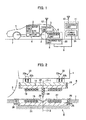
- FIG. 1 is a diagram showing an entire configuration of a wireless charging system according to a first embodiment of the present invention.
- the wireless charging system shown in the figure includes a receiver unit (electric power receiving portion) 6 connected to a secondary battery 2, and a transmitter unit (electric power feeding portion) 8 for supplying electric power to the receiver unit 6 in a wireless manner by utilizing a mutual interaction of the electromagnetic induction.
- a coil portion 18 (described later) of the receiver unit 6, and a coil portion 15 (described later) of the transmitter unit 8 are made close to each other to be disposed so as to face each other, thereby feeding the electric power from the coil portion 15 to the coil portion 18.
- an electric moving vehicle 1 for example, an electric vehicle shown in FIG.
- the wireless charging system according to the present invention can be applied to the movable body as long as a movable body includes a chargeable battery.
- the receiver unit 6 includes a coil portion (secondary coil) 18 and a magnetic material portion 14 both of which will be described later, and is connected to the secondary battery 2 through a reception side control unit 5.
- the electric power which has been supplied from the transmitter unit 8 is stored in the secondary battery 2.
- the electric power stored in the secondary battery 2 is supplied to a motor 4 which is mechanically coupled to a wheel 3 to drive the motor 4. As a result, the electric moving vehicle 1 travels.
- a control unit 5 serves to mainly execute processing about charging control for the secondary battery 2.
- An antenna 12 is connected to the control unit 5.
- the antenna 12 gives and receives various information such as start and end of the charging for the secondary battery 2, and states (such as temperatures and relative positions of the coil portions 18 and 15) of the receiver unit 6 and the transmitter unit 8 between an antenna 13 which will be described later of the transmitter unit 8, and the antenna 12.
- the transmitter unit 8 includes a coil portion (primary coil) 15 and a magnetic material portion 21 both of which will be described later, and is connected to a power source 10 through a cable (electric power line) 9.
- the power source 10 is connected to an electric power feeding control unit 11.
- a control unit 11 serves to mainly execute processing about the electric power feeding control for the receiver unit 6.
- An antenna 13 is connected to the control unit 11.
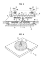
- FIGS. 2 and 3 are respectively enlarged views of the circumference of the receiver unit 6 and the transmitter unit 8 in the wireless charging system 1 according to the first embodiment of the present invention.
- FIG. 2 shows a non-charging state
- FIG. 3 shows a state during the charging. It is noted that in FIGS. 2 and 3 , the same portions as those in FIG. 1 are designated by the same reference numerals or symbols, respectively, and a description thereof may be suitably omitted in some cases (this also applies to each of figures following FIGS. 2 and 3 ).
- the receiver unit 6 includes a magnetic member 14 made of a magnetic material, and an approximately flat-shaped coil portion (secondary coil) 18 which is formed by wiring an electric wire around a predetermined axis (a central axis 17-1 in the case shown in FIGS. 2 and 3 ). Also, the receiver unit 6 includes a convex portion 24 mounted to the magnetic member 14, and a lifting mechanism 23 for making the coil portion 18 close to the transmitter unit 8.
- the coil portion 18 is fixed to a surface of the magnetic member 14 by, for example, an adhesive agent such as a resin.
- the coil portion 18 is approximately, horizontally adhered to a lower surface (a surface on the ground 7 side) of the magnetic member 14 so as to be able to face the coil portion 15 on the side of the transmitter unit 8 which is fixed approximately, horizontally as will be described later in a state in which a central axis 17-1 of the coil portion 18, and a central axis 17-2 of the coil portion 15 are aligned with each other.
- the coil portion 18 in the first embodiment is provided so as to be positioned in the outside (outer surface side) of the electric moving vehicle 1 relative to the magnetic member 14 and so as to be able to face the coil portion 15 installed outside the electric moving vehicle 1 on the same axis. It is noted that with regard to the material of the coil portion 18, a litz wire or the like is preferable because it reduces an eddy-current loss due to a skin effect.
- the magnetic member 14 shown in the figure is formed in a plate-like shape, and is approximately horizontally fixed to a supporting base 22 formed in a plate-like shape through a fixing bracket 19. It is noted that with regard to the material of the magnetic member 14, a material such as ferrite is preferable because it reduces the eddy current.
- the supporting base 22 is approximately horizontally mounted to a bottom surface of the electric moving vehicle 1 through the lifting mechanism 23. It is noted that with regard to the material of the supporting base 22, a non-magnetic material such as aluminum is preferable.
- the lifting mechanism 23 ascends/descends the receiver unit 6 in accordance with a signal from the reception side control unit 5.
- the lifting mechanism 23 shown in FIGS. 2 and 3 includes two motors 23a having male screws provided in output axes thereof, and two supporting portions 23b in which female screw portions which are screwed into the male screw portions of the two motors 23a are provided, respectively.
- the supporting portion 23b is ascended/descended in correspondence to a rotational direction of the motors 23a, thereby ascending/descending the receiver unit 6.
- the coil portion 18 When the coil portion 18 is installed so as to be able to be ascended/descended approximately in the vertical direction by the lifting mechanism 23, during the traveling of the electric moving vehicle 1, the coil portion 18 or the like can be prevented from colliding with an obstacle, and during the charging, the reception side coil portion 18 can be made close to the transmission side coil portion 15.
- the convex portion (protrusion portion) 24 is mounted to the magnetic member 14, and protrudes toward the magnetic member 21 of the transmitter unit 8 when the two coil portions 15 and 18 are coaxially disposed in the manner as shown in FIG. 2 .
- the convex portion 24 shown in FIGS. 2 and 3 is mounted to the magnetic member 14 in such a way that an upper end of the convex portion 24 is located at the center of the coil portion 18. Also, the convex portion 24 protrudes from a hollow portion in the coil portion 18.
- the shaft center of the convex portion 24 is approximately aligned with the central axis 17-1 of the coil portion 18.
- the convex portion 24 is larger in a size thereof in a direction (in a length direction) along the central axis 17-1 of the coil portion 18 than in a size of the coil portion 18 in a direction (in a width direction) along a radial direction thereof.
- the size of the convex portion 24 in the length direction thereof is ensured to be larger than the length along which the convex portion 24 can come in contact with the concave portion 29 when the reception side coil portion 18 and the transmission side coil portion 15 are made close to each other in the phase of the charging.
- the convex portion 24 contains therein as a material thereof a magnetic material from a viewpoint of formation of the magnetic path. Moreover, when the convex portion 24 gets away from other object, the convex portion 24 preferably returns in a shape thereof back to the original shape even after the convex portion 24 has come in contact with other object to be deformed in the manner as described above.
- the convex portion 24 is preferably made of a mixture of a material having a small Young's modulus, and a magnetic material.
- a magnetic rubber is preferable which contains therein a resin and a magnetic material in a mixing manner.
- the convex portion 24 may be a spring made of a metal.
- FIG. 4 is a perspective view of the coil portion 18, the magnetic member 14, and the convex portion 24 of the receiver unit 6 in the wireless charging system 1 according to the first embodiment of the present invention when viewed from the transmitter unit 8 side.
- the convex portion 24 is disposed at the center of the coil portion 18, and the convex portion 24 gradually decreases in radius as it further gets away from the magnetic member 14. That is to say, when the two coil portions 15 and 18 are coaxially disposed, the convex portion 24 gradually decreases toward the transmission side coil portion 15 (the transmitter unit 8) while it extends along the axial direction 17-1 of the reception side coil portion 18.
- the convex portion 24 is easy to guide into the concave portion 29.
- the transmitter unit 8 is stored in a storage container 25 which is embedded in a hole dug in the ground 7. Also, the transmitter unit 8 includes a magnetic member 21 made of a magnetic material, an approximately flat coil portion (primary coil) 15 which is formed by winding an electric wire around a predetermined axis (the central axis 17-2 in the cases of FIGS. 2 and 3 ), the cover 27 for covering the coil portion 15, and a concave portion 29 provided in the cover 27.
- FIG. 5 is a perspective view of the coil portion 15 and the magnetic member 21 of the transmitter unit 8 in the first embodiment of the present invention when viewed from the receiver unit 6 side.
- the coil portion 15 is fixed to a surface of the magnetic member 21 by an adhesive agent such as a resin, or the like.
- the coil portion 15 is approximately horizontally adhered to an upper surface of the magnetic member 21 so as to be able to face the coil portion 18 on the receiver unit 6 side in a state in which the central axis 17-1 of the coil portion 18, and the central axis 17-2 of the coil portion 15 are aligned with each other.
- a litz wire or the like is preferable because it reduces the eddy-current loss due to the skin effect.
- the magnetic member 21 is formed in a plate-like shape, and is approximately horizontally fixed within a storage container 25 through a fixing bracket 26.
- a material such as ferrite is preferable because it reduces the eddy current.
- An opening portion is provided in an upper portion of the storage container 25 and is covered with the cover 27.
- the cover 27 is fixed to the ground 7 so as to be unable to be relatively moved with respect to the coil portion 15.
- a storage bracket 25 supports together with the cover 27 a weight of an object (such as the human being or the automobile) which comes and goes on the ground 7, and protects both of the coil portion 15 and the magnetic member 21 from the object.
- a high-resistance non-magnetic member such as a fiber-reinforced plastic (FRP) or an austenitic stainless steel.
- the concave portion 29 is depressed in a mortar-like shape toward the magnetic member 21. Also, the concave portion 29 is provided in the cover 27 so as to face the convex portion 24 when as shown in FIG. 2 , the two coil portions 15 and 18 are coaxially disposed. That is to say, the center of the concave portion 29 is approximately aligned with the central axis 17-2 of the coil portion 15.
- a size (a diameter of an opening end of the concave portion 29) of the end portion on the receiver unit 6 side in the concave portion 29 is formed to be larger than that (a diameter of the lower end) of the end portion on the transmitter unit 8 side in the convex portion 24, which allows the lower end (tip) of the convex portion 24 to be introduced into the concave portion 29.
- the concave portion 29 in the first embodiment gradually increases in diameter as it further gets away from the magnetic member 21. That is to say, when the two coil portions 15 and 18 are coaxially disposed, the concave portion 29 gradually increases in diameter toward the reception side coil portion 18 (the receiver unit 6) while it extends along the axial direction 17-2 of the transmission side coil portion 15.
- the tip of the convex portion 24 can be guided to a desired position as the receiver unit 6 and the transmitter unit 8 are made close to each other.
- the concave portion 29 shown in FIGS. 2 and 3 is the approximately conical depression, and such cone and the coil portion 15 have the central axis 17-2 in common.
- the tip of the convex portion 24 is guided to the center of the coil portion 15.
- a driver of the electric moving vehicle 1 moves the electric moving vehicle 1 in such a way that a relative distance between the transmitter unit 8 and the receiver unit 6 (a relative distance between the central axis 17-1 and the central axis 17-2) which is detected through the antennas 12 and 13 falls within a predetermined range, and carries out the positioning of the electric moving vehicle 1.
- the paired coil portions 15 and 18 in the transmitter unit 8 and the receiver unit 6 are disposed so as to face each other.
- a signal is sent to the lifting mechanism 23.
- This signal is used to descend the receiver unit 6 by a predetermined distance in accordance with, for example, an instruction issued by the driver of the electric moving vehicle 1, an instruction from the software previously set based on information on the relative distance between the transmitter unit 8 and the receiver unit 6, or an instruction directly inputted from the operator such as the driver to the transmission side control unit 11.
- the motor 23a descends the receiver unit 6 to the transmitter unit 8 side.
- an energization start instruction is issued from the transmission side control unit 11 to the power source 10.
- an A.C. current having a predetermined frequency for example, 10 kHz
- an induced current is caused to flow through the reception side coil portion 18 by an electromagnetic induction operation caused by an A.C. magnetic field formed by the transmission side coil portion 15 interlinking the reception side coil portion 18, thereby charging the secondary battery 2 with the electricity via a rectifier (not shown).
- FIG. 6 is a sectional view showing magnetic field lines in the phase of the charging when the imperfect alignment is caused between a transmitter unit 80 and a receiver unit 60 in a conventional wireless charging system.
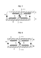
- FIG. 7 is a sectional view showing magnetic field lines in the phase of the charging when the imperfect alignment is caused between the transmitter unit 8 and the receiver unit 6 in a wireless charging system according to the first embodiment of the present invention.
- FIG. 8 is a sectional view showing magnetic field lines in the phase of the charging when the central axes of the transmitter unit 80 and the receiver unit 60 are aligned with each other in the conventional wireless charging system.
- the electric power feeding efficiency between the transmitter unit 80 and the receiver unit 60 is reduced.
- the magnetic fluxes pass through the concave portion 24 which contains therein the magnetic material and which has the low magnetic resistance. For this reason, the state can be made close to the state as shown in FIG.
- the control unit 5 on the receiver unit 6 side either detects this state, or receives an end instruction issued by the operator. As a result, a command about energization end is transmitted to the control unit 11 of the transmitter unit 8 through both of the antennas 12 and 13. Then, the control unit 11 transmits a signal about the energization end to the power source 10 (otherwise, the energization by the power source 10 may be ended in accordance with a direct end instruction to the control unit 11 by the operator). Also, the reception side control unit 5 sends a signal to the lifting mechanism 23 to ascend the receiver unit 6 up to a predetermined position, thereby completing a series of charging operations.
- the convex portion 24 (magnetic path) is disposed on the magnetic circuit, which allows most of the magnetic field lines generated by both of the transmitter unit 8 and the receiver unit 6 to pass through the ferromagnetic material. Thus the leaked magnetic field to the circumferences can be reduced. In addition, the high-electric power efficiency can also be devoted to the reduction of the cost.
- the charging time equal to conventional one can be attained with the electric transmission current less than conventional one
- the thin conductor which is more inexpensive than conventional one can be applied as the conductor of the coil portions 15 and 18.
- the inexpensive power source whose output electric power is lower than conventional one can be applied.
- the distance between the transmitter unit and the receiver unit can be widely ensured in a phase other than the phase of the charging, it is possible to reduce the chances of the transmitter unit 8 and the receiver unit 6 colliding with the obstacle.
- the shape of the convex portion 24 is preferably the conical shape, the shape of the convex portion 24 may have any other suitable structure such as a column or a prism. Also, the shape of the convex portion 24 may have the structure which will be described below.
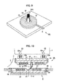
- FIG. 9 is a perspective view of a convex portion 24A of a receiver unit 6A in a wireless charging system according to a first modified change of the first embodiment of the present invention when viewed from the transmitter unit 8 side.
- FIG. 10 is an enlarged view of the circumference of the receiver unit 6A and the transmitter unit 8 shown in FIG. 9 .
- the convex portion 24A shown in FIGS. 9 and 10 includes a large diameter portion 91 made of a columnar magnetic rubber and mounted to the magnetic member 14, and a small diameter portion 92 made of plural linear magnetic rubbers standing together in large number on the tip of the large diameter portion 91. Each of diameters of the magnetic rubbers composing the small diameter portion 92 is smaller than that of the large diameter portion 91.
- the small diameter portion 92 located at the tip of the convex portion 24A as shown in FIG. 10 can be deformed so as to follow a tapered surface (inclined surface) of the convex portion 29.
- a piano wire or the like may be utilized as the linear object of the small diameter portion 92.
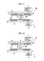
- FIG. 11 is a schematic view of a convex portion 24B of a receiver unit 6B in a wireless charging system according to a second modified change of the first embodiment of the present invention.
- the convex portion 24B shown in FIG. 11 is composed of only the small diameter portion 92 shown in FIGS. 9 and 10 , and is made of plural linear magnetic rubbers standing together in large numbers on the magnetic member 14. Even when the convex portion 24B is structured in the manner as described above, the tips of the convex portion 24B can be deformed so as to follow the tapered surface of the concave portion 29. Thus, the same effects as those in the first embodiment can be obtained.
- FIG. 12 is a schematic view of a convex portion 24C of a receiver unit 6C in a wireless charging system according to a third modified change of the first embodiment of the present invention.
- the convex portion 24C shown in FIG. 12 includes an approximately columnar base portion 31 mounted to the magnetic member 14, a mediate portion 32 provided at the tip of the base portion 31, and an approximately cylindrical tip portion 33 mounted to the mediate portion 32.
- the tip portion 33 and the base portion 31 are mutually rotatably held through the mediate portion 32.
- each of the tip portion 33 and the base portion 31 contains therein a magnetic material, the tip portion 33 and the base portion 31 may be made of different materials, respectively, as other materials except for the magnetic material.
- a material having a Young's modulus which is smaller than that of the base portion 31 is preferably selected as other material of the tip portion 33. Even when the convex portion 24C is formed in such a manner, the tip portion 33 is pivoted through the mediate portion 32. Therefore, since the tip of the convex portion 24C can be deformed so as to follow the tapered surface of the concave portion 29, it is possible to obtain the same effects as those in the first embodiment.
- FIG. 13 is an enlarged view of a circumference of a receiver unit 6D and a transmitter unit 8D in a wireless charging system according to a second embodiment of the present invention (during charging).
- FIG. 14 is a perspective view of the receiver unit 6D in the wireless charging system according to the second embodiment of the present invention when viewed from the transmitter unit 8D side.
- the receiver unit 6D also includes an approximately annular convex portion 24D in addition to the convex portion 24 in the first embodiment.
- the convex portion 24D is disposed in the outer periphery of the coil portion 18 and is formed by dividing a columnar surface having a larger inner diameter than an outer diameter of the coil portion 18.
- the columnar surface with the central axis 17-1 as a center is divided into three parts to obtain the convex portion 24D.
- a thickness of the convex portion 24D is preferably made small as it further gets away from the magnetic member 14 similarly to the case of the diameter of the convex portion 24.
- the convex portion 24D contains therein as a material thereof a magnetic material similarly to the case of the convex portion 24, and a magnetic rubber, for example, is preferable as the material of the convex portion 24D.
- the transmitter unit 8D further includes a cover 27D which is provided with an approximately annular concave portion 29D in addition to the concave portion 29 in the first embodiment.
- the cover 27D is a depression which is provided in the cover 27D so as to face the convex portion 24D when the two coil portions 15 and 18 are coaxially disposed, and is provided in a circular shape in the outer periphery of the coil portion 15 in the second embodiment.
- a size (a difference between an inner diameter and an outer diameter) of the concave portion 29D in the radial direction of the coil portion 15 is preferably formed so as to become large as it further gets away from the magnetic member 21.
- the concave portion 29D shown in the figure has a V letter-like shape in cross section. It is noted that the concave portion 29D may be made as an arc-like set which is obtained by dividing a circle into three parts so as to correspond to the shape of the concave portion 24D.
- the receiver unit 6D is descended to the transmitter unit 8D side by the lifting mechanism 23.
- the central axes 17-2 and 17-1 of the two coil portions 15 and 18 are slightly misaligned with each other, if the tips of the convex portion 24 and the convex portion 24D which are disposed in the receiver unit 6D are guided into the concave portion 29 or the concave portion 29D of the transmitter unit 8D, then, the magnetic path is formed by both of the convex portion 24 and the convex portion 24D.
- the tip of the concave portion 24D is moved along an inclined surface of the concave portion 29D of the transmitter unit 8, whereby the convex portion 24D is deformed to form the magnetic path through which the outer periphery of the reception side coil portion 18, and the outer periphery of the transmission side coil portion 15 are connected to each other.
- the magnetic fluxes pass through the convex portion 24 and the convex portion 24D each having the low-magnetic resistance. For this reason, it is possible to increase the coupling coefficient between the transmitter unit 8D and the receiver unit 6D.
- the magnetic path through which the transmitter unit 8D and the receiver unit 6D are coupled to each other is formed by both of the convex portion 24 and the convex portion 24D.
- the reduction of the electric power feeding efficiency can be suppressed.
- the magnetic field lines which cannot interlink in the first embodiment can interlink the receiver unit 18 by the magnetic path generated by the convex portion 24D. Therefore, it is possible to further suppress the reduction of the electric power feeding efficiency.
- the thickness of the convex portion 24D is preferably decreased as it further gets away from the magnetic member 14, the thickness of the convex portion 24D may be set as a given thickness.
- the convex portion 24D may be composed of only plural linear magnetic rubbers which stand together in large numbers, or as shown in FIG. 12 , the convex portion 24D may include the mediate portion 32.
- each of the convex portion 24B, and the convex portion 24E located in the outer periphery of the convex portion 24B may be composed of the linear magnetic rubber.
- the description has been given with respect to the case where the convex portion 24, and the convex portion 24D in the outer periphery of the convex portion 24 are provided, even in the case where the convex portion 24 is omitted and only the convex portion 24D is provided, it is possible to suppress the reduction of the electric power feeding efficiency.
- the convex portion 24 and the convex portion 24D need not be entirely made of the same material. If only each of tip portions of the convex portion 24 and the convex portion 24D is made of a mixed member consisting of a resin and a magnetic material, the convex portion 24 and the convex portion 24D can be deformed so as to follow the tapered surfaces of the concave portion 29 and the concave portion 29D, respectively. As a result, the effects of the present invention can be obtained.
- FIG. 16 is an enlarged view of a circumference of a receiver unit 6 and a transmitter unit 8 in a wireless charging system according to a third embodiment of the present invention (non-charging).
- Supporting portions 23b shown in the figure support the supporting base 22 through springs 61, respectively.
- Each of the springs 61 functions as supporting means for swingably supporting the magnetic member 14 in the radial direction of the coil portion 18.
- the magnetic member 14 is swingably supported in such a manner, even in the case where the central axes 17-2 and 17-1 of the two coil portions 15 and 18 are slightly misaligned with each other when the receiver unit 6 is descended to the transmitter unit 8 side, if the tip of the convex portion 24 is guided into the concave portion 29, then, the magnetic member 14 is moved approximately in the horizontal direction as the receiver unit 6 is further descended. Therefore, even when the convex portion 24 is not bent, the magnetic path can be formed by the convex portion 24. Therefore, similarly to the cases of the first and second embodiments described above, the reduction of the electric power feeding efficiency can be suppressed. It is noted that from the viewpoint of readily moving the magnetic member 14, a material whose Young's modulus (whose rigidity) is larger than that of the spring 61 is preferably selected as the main material of the convex portion 24 in the third embodiment.
- the transmitter unit 8 is made close to the receiver unit 6.
- the convex portion is provided in the transmitter unit, and the concave portion is provided in the receiver unit.
- the receiver unit 6 shown in FIG. 1 is installed on the bottom surface of the electric moving vehicle 1 so as to face the ground 7 in which the transmitter unit 8 is embedded. However, it is only necessary that the receiver unit 6 shown in FIG. 1 is disposed so as to face the transmitter unit 8.
- the receiver unit 6 shown in FIG. 1 may also be installed in any other suitable place so as to correspond to the installation position of the transmitter unit 8.
- the transmitter unit 8 is installed on the side surface of the electric moving vehicle 1
- the receiver unit 6 is installed on the side surface of the electric moving vehicle 1 so as to face the transmitter unit 8.
- the transmitter unit 8 is installed above the electric moving vehicle 1, it is only necessary that the receiver unit 6 is installed on the upper surface of the electric moving vehicle 1.
- the transmitter unit 8 shown in FIG. 1 is embedded in the ground (road surface) 7
- the transmitter unit 8 may also be installed in any other suitable place as long as the transmitter unit 8 is disposed so as to face the receiver unit 6 in the manner as previously stated.
Landscapes
- Engineering & Computer Science (AREA)
- Power Engineering (AREA)
- Computer Networks & Wireless Communication (AREA)
- Transportation (AREA)
- Mechanical Engineering (AREA)
- Charge And Discharge Circuits For Batteries Or The Like (AREA)
- Electric Propulsion And Braking For Vehicles (AREA)
- Current-Collector Devices For Electrically Propelled Vehicles (AREA)
Applications Claiming Priority (1)
| Application Number | Priority Date | Filing Date | Title |
|---|---|---|---|
| JP2012160716A JP5938288B2 (ja) | 2012-07-19 | 2012-07-19 | 無線給電装置 |
Publications (2)
| Publication Number | Publication Date |
|---|---|
| EP2688182A2 true EP2688182A2 (de) | 2014-01-22 |
| EP2688182A3 EP2688182A3 (de) | 2016-11-16 |
Family
ID=48795437
Family Applications (1)
| Application Number | Title | Priority Date | Filing Date |
|---|---|---|---|
| EP13176695.8A Withdrawn EP2688182A3 (de) | 2012-07-19 | 2013-07-16 | Drahtloses Ladesystem |
Country Status (3)
| Country | Link |
|---|---|
| US (1) | US9143001B2 (de) |
| EP (1) | EP2688182A3 (de) |
| JP (1) | JP5938288B2 (de) |
Cited By (4)
| Publication number | Priority date | Publication date | Assignee | Title |
|---|---|---|---|---|
| CN104201738A (zh) * | 2014-08-20 | 2014-12-10 | 中兴通讯股份有限公司 | 电子设备的无线充电方法及装置、电子设备 |
| EP3131177A4 (de) * | 2014-03-26 | 2018-01-03 | IHI Corporation | Kontaktloses energieversorgungssystem und energieversorgungssystem für ein objekt |
| CN108407650A (zh) * | 2018-04-13 | 2018-08-17 | 英华达(上海)科技有限公司 | 汽车无线充电方法、系统及地面侧充电系统 |
| CN109398118A (zh) * | 2018-11-09 | 2019-03-01 | 长沙龙生光启新材料科技有限公司 | 一种电动车辆智能对准系统 |
Families Citing this family (25)
| Publication number | Priority date | Publication date | Assignee | Title |
|---|---|---|---|---|
| US9577464B2 (en) | 2012-02-27 | 2017-02-21 | Hitachi Power Solutions Co., Ltd. | Wireless charging system |
| KR101697418B1 (ko) * | 2012-05-09 | 2017-01-17 | 도요타지도샤가부시키가이샤 | 차량 |
| CN104956568B (zh) * | 2013-02-08 | 2017-06-23 | 株式会社 Ihi | 传热装置、供电装置和非接触供电系统 |
| US9586493B2 (en) * | 2013-02-27 | 2017-03-07 | Satyajit Patwardhan | Hands free conductive charging system for electric vehicles |
| JP2014241673A (ja) * | 2013-06-11 | 2014-12-25 | 株式会社東芝 | 電磁波漏洩防止装置 |
| CN105593053A (zh) * | 2013-09-27 | 2016-05-18 | 日产自动车株式会社 | 非接触受电装置的车载构造 |
| EP2950422A1 (de) * | 2014-05-16 | 2015-12-02 | Samsung Electro-Mechanics Co., Ltd. | Drahtlose ladestation mit sender und empfänger |
| US9948112B2 (en) | 2014-09-26 | 2018-04-17 | Integrated Device Technology, Inc. | Apparatuses and related methods for detecting coil alignment with a wireless power receiver |
| US10106045B2 (en) | 2014-10-27 | 2018-10-23 | At&T Intellectual Property I, L.P. | Methods and apparatus to charge a vehicle and to facilitate communications with the vehicle |
| US9984815B2 (en) * | 2014-12-22 | 2018-05-29 | Eaton Capital Unlimited Company | Wireless power transfer apparatus and power supplies including overlapping magnetic cores |
| US10625612B2 (en) | 2015-04-15 | 2020-04-21 | Ford Global Technologies, Llc | Deployable vehicle inductive charging assembly |
| DE102015006310B4 (de) * | 2015-05-16 | 2022-01-27 | Audi Ag | Ladevorrichtung zum induktiven Laden eines elektrischen Energiespeichers eines Kraftfahrzeugs und Verfahren zum Betreiben einer Ladevorrichtung |
| JP6272287B2 (ja) * | 2015-10-27 | 2018-01-31 | 矢崎総業株式会社 | 非接触電力伝送ユニット |
| DE102016203933A1 (de) * | 2016-03-10 | 2017-09-14 | Bayerische Motoren Werke Aktiengesellschaft | Induktionsaufladesystem für Fahrzeug sowie Verwendung |
| JP6369493B2 (ja) | 2016-03-30 | 2018-08-08 | Tdk株式会社 | 給電コイルユニット、ワイヤレス給電装置およびワイヤレス電力伝送装置 |
| US10304604B2 (en) * | 2016-05-03 | 2019-05-28 | The United States Of America As Represented By The Secretary Of The Army | Deformable inductive devices having a magnetic core formed of an elastomer with magnetic particles therein along with a deformable electrode |
| KR101848416B1 (ko) * | 2016-05-18 | 2018-04-12 | 주식회사 아모그린텍 | 차량용 무선 전력 송신장치 |
| US10298061B2 (en) * | 2016-09-07 | 2019-05-21 | Thunder Power New Energy Vehicle Development Company Limited | Wireless vehicle recharging system |
| CN107294217A (zh) * | 2017-06-26 | 2017-10-24 | 西安电子科技大学 | 一种非接触式电能传输装置 |
| CN107453447B (zh) * | 2017-09-19 | 2023-09-26 | 东莞市太业电子股份有限公司 | 通用型无线充电装置 |
| CN108054804B (zh) * | 2018-01-08 | 2023-12-26 | 内蒙古聚能节能服务有限公司 | 一种翻转式充电线圈 |
| CN111505402B (zh) * | 2019-01-31 | 2022-08-23 | 致茂电子(苏州)有限公司 | 车辆用无线充电模块的检测设备及其检测方法 |
| CN109986977A (zh) * | 2019-04-17 | 2019-07-09 | 合芯磁导科技(无锡)有限公司 | 一种安全智能节能型无线充电发射器的防水淹机构 |
| US11990766B2 (en) | 2019-07-02 | 2024-05-21 | Eaton Intelligent Power Limited | Wireless power transfer apparatus with radially arrayed magnetic structures |
| CN116945924A (zh) * | 2023-06-07 | 2023-10-27 | 熊乔 | 电动汽车静态电场式无线充电系统、电磁安全及配套设计 |
Citations (3)
| Publication number | Priority date | Publication date | Assignee | Title |
|---|---|---|---|---|
| JPH08265992A (ja) | 1995-03-24 | 1996-10-11 | Toyota Autom Loom Works Ltd | 充電装置の充電方法及び充電装置の位置決め装置 |
| JP4356844B2 (ja) | 2006-10-05 | 2009-11-04 | 昭和飛行機工業株式会社 | 非接触給電装置 |
| JP2011151351A (ja) | 2009-12-21 | 2011-08-04 | Nok Corp | 非接触給電装置 |
Family Cites Families (11)
| Publication number | Priority date | Publication date | Assignee | Title |
|---|---|---|---|---|
| JP2820706B2 (ja) * | 1989-03-02 | 1998-11-05 | 株式会社日本自動車部品総合研究所 | 電磁結合用のコイルを有する電力供給装置 |
| US5617003A (en) | 1995-03-24 | 1997-04-01 | Kabushiki Kaisha Toyoda Jidoshokki Seisakusho | Method and apparatus for charging a battery of an electric vehicle |
| JP3169817B2 (ja) * | 1996-01-30 | 2001-05-28 | 三菱電機株式会社 | 磁気結合信号伝送装置 |
| JPH1075538A (ja) * | 1996-06-27 | 1998-03-17 | Sumitomo Wiring Syst Ltd | 充電用コネクタ |
| JP3697789B2 (ja) * | 1996-09-20 | 2005-09-21 | 松下電器産業株式会社 | 非接触型電源装置 |
| JP3437119B2 (ja) * | 1999-06-07 | 2003-08-18 | 株式会社オートネットワーク技術研究所 | 電磁誘導型コネクタ |
| JP2010123729A (ja) * | 2008-11-19 | 2010-06-03 | Nec Tokin Corp | 非接触型電力伝送装置 |
| KR100944113B1 (ko) * | 2009-02-27 | 2010-02-24 | 한국과학기술원 | 전기자동차용 전원공급 시스템 및 방법 |
| JP5593977B2 (ja) * | 2010-09-01 | 2014-09-24 | Nok株式会社 | 非接触給電装置 |
| JP5574107B2 (ja) * | 2010-10-13 | 2014-08-20 | 三菱自動車工業株式会社 | 車両用充電装置 |
| CN108868747A (zh) * | 2011-11-03 | 2018-11-23 | 快帽系统公司 | 生产测井仪 |
-
2012
- 2012-07-19 JP JP2012160716A patent/JP5938288B2/ja not_active Expired - Fee Related
-
2013
- 2013-07-16 EP EP13176695.8A patent/EP2688182A3/de not_active Withdrawn
- 2013-07-19 US US13/946,347 patent/US9143001B2/en active Active
Patent Citations (3)
| Publication number | Priority date | Publication date | Assignee | Title |
|---|---|---|---|---|
| JPH08265992A (ja) | 1995-03-24 | 1996-10-11 | Toyota Autom Loom Works Ltd | 充電装置の充電方法及び充電装置の位置決め装置 |
| JP4356844B2 (ja) | 2006-10-05 | 2009-11-04 | 昭和飛行機工業株式会社 | 非接触給電装置 |
| JP2011151351A (ja) | 2009-12-21 | 2011-08-04 | Nok Corp | 非接触給電装置 |
Cited By (8)
| Publication number | Priority date | Publication date | Assignee | Title |
|---|---|---|---|---|
| EP3131177A4 (de) * | 2014-03-26 | 2018-01-03 | IHI Corporation | Kontaktloses energieversorgungssystem und energieversorgungssystem für ein objekt |
| US10348118B2 (en) | 2014-03-26 | 2019-07-09 | Ihi Corporation | Wireless power transfer system and object power supply device |
| CN104201738A (zh) * | 2014-08-20 | 2014-12-10 | 中兴通讯股份有限公司 | 电子设备的无线充电方法及装置、电子设备 |
| EP3197012A4 (de) * | 2014-08-20 | 2017-08-23 | ZTE Corporation | Elektronische vorrichtung und drahtloses ladeverfahren sowie vorrichtung dafür |
| US10432038B2 (en) | 2014-08-20 | 2019-10-01 | Xi'an Zhongxing New Software Co., Ltd. | Electronic device and wireless charging method and apparatus for electronic device |
| CN108407650A (zh) * | 2018-04-13 | 2018-08-17 | 英华达(上海)科技有限公司 | 汽车无线充电方法、系统及地面侧充电系统 |
| CN108407650B (zh) * | 2018-04-13 | 2020-10-27 | 英华达(上海)科技有限公司 | 汽车无线充电方法、系统及地面侧充电系统 |
| CN109398118A (zh) * | 2018-11-09 | 2019-03-01 | 长沙龙生光启新材料科技有限公司 | 一种电动车辆智能对准系统 |
Also Published As
| Publication number | Publication date |
|---|---|
| EP2688182A3 (de) | 2016-11-16 |
| US9143001B2 (en) | 2015-09-22 |
| US20140035520A1 (en) | 2014-02-06 |
| JP5938288B2 (ja) | 2016-06-22 |
| JP2014023315A (ja) | 2014-02-03 |
Similar Documents
| Publication | Publication Date | Title |
|---|---|---|
| US9143001B2 (en) | Wireless charging system | |
| EP2824793A1 (de) | Drahtlose stromversorgungsvorrichtung | |
| US8482161B2 (en) | Inductive power supply system with overlapping coils | |
| KR101985490B1 (ko) | 무선 충전 디바이스 및 이를 이용한 차량 무선 충전 방법 | |
| JP2003061266A (ja) | 移動体システム | |
| US10576842B2 (en) | Electricity supply apparatus and electricity reception apparatus | |
| US20210050743A1 (en) | Wireless charging system for portable terminal | |
| JP2010183814A (ja) | 非接触電力伝送装置 | |
| CN109311407A (zh) | 电连接系统 | |
| JP2013208054A (ja) | 給電装置 | |
| US20140306655A1 (en) | Contactless battery charger | |
| US20200079234A1 (en) | Unmanned aerial vehicle, unmanned aerial vehicle system, and battery system | |
| JP6076321B2 (ja) | 非接触給電システム及び電動車両 | |
| JP5118776B1 (ja) | 給電装置 | |
| WO2013136787A1 (ja) | 給電装置、受電装置及び給電システム | |
| WO2016072351A1 (ja) | コイル装置、非接触給電システムおよび補助磁性部材 | |
| JP2021027755A (ja) | 非接触給電システム及び非接触受電装置 | |
| JP2013090392A (ja) | 非接触充電装置及び非接触給電設備 | |
| KR102794293B1 (ko) | 전기자동차 충전 시스템 및 그 충전방법 | |
| JP2018064326A (ja) | 送電装置 | |
| KR20180043129A (ko) | 편차에 강인한 무선전력 충전시스템 | |
| JP6354565B2 (ja) | 受電装置 | |
| JP2013141350A (ja) | 非接触給電システム及び車両 | |
| JP2025112612A (ja) | コイル及び電力授受装置 | |
| JP2014117073A (ja) | 非接触充電車両用の通信装置 |
Legal Events
| Date | Code | Title | Description |
|---|---|---|---|
| PUAI | Public reference made under article 153(3) epc to a published international application that has entered the european phase |
Free format text: ORIGINAL CODE: 0009012 |
|
| 17P | Request for examination filed |
Effective date: 20130731 |
|
| AK | Designated contracting states |
Kind code of ref document: A2 Designated state(s): AL AT BE BG CH CY CZ DE DK EE ES FI FR GB GR HR HU IE IS IT LI LT LU LV MC MK MT NL NO PL PT RO RS SE SI SK SM TR |
|
| AX | Request for extension of the european patent |
Extension state: BA ME |
|
| PUAL | Search report despatched |
Free format text: ORIGINAL CODE: 0009013 |
|
| AK | Designated contracting states |
Kind code of ref document: A3 Designated state(s): AL AT BE BG CH CY CZ DE DK EE ES FI FR GB GR HR HU IE IS IT LI LT LU LV MC MK MT NL NO PL PT RO RS SE SI SK SM TR |
|
| AX | Request for extension of the european patent |
Extension state: BA ME |
|
| RIC1 | Information provided on ipc code assigned before grant |
Ipc: H02J 7/02 20060101AFI20161012BHEP Ipc: B60L 11/18 20060101ALI20161012BHEP Ipc: H02J 17/00 00000000ALI20161012BHEP |
|
| STAA | Information on the status of an ep patent application or granted ep patent |
Free format text: STATUS: THE APPLICATION HAS BEEN WITHDRAWN |
|
| 18W | Application withdrawn |
Effective date: 20170111 |