EP2688220A1 - Verfahren zum senden und empfangen von kanalstatusinformationen und sendevorrichtung dafür - Google Patents
Verfahren zum senden und empfangen von kanalstatusinformationen und sendevorrichtung dafür Download PDFInfo
- Publication number
- EP2688220A1 EP2688220A1 EP12757685.8A EP12757685A EP2688220A1 EP 2688220 A1 EP2688220 A1 EP 2688220A1 EP 12757685 A EP12757685 A EP 12757685A EP 2688220 A1 EP2688220 A1 EP 2688220A1
- Authority
- EP
- European Patent Office
- Prior art keywords
- nodes
- state information
- channel state
- interference
- cooperative transmission
- Prior art date
- Legal status (The legal status is an assumption and is not a legal conclusion. Google has not performed a legal analysis and makes no representation as to the accuracy of the status listed.)
- Withdrawn
Links
Images


Classifications
-
- H—ELECTRICITY
- H04—ELECTRIC COMMUNICATION TECHNIQUE
- H04W—WIRELESS COMMUNICATION NETWORKS
- H04W24/00—Supervisory, monitoring or testing arrangements
- H04W24/10—Scheduling measurement reports ; Arrangements for measurement reports
-
- H—ELECTRICITY
- H04—ELECTRIC COMMUNICATION TECHNIQUE
- H04B—TRANSMISSION
- H04B7/00—Radio transmission systems, i.e. using radiation field
- H04B7/02—Diversity systems; Multi-antenna system, i.e. transmission or reception using multiple antennas
- H04B7/022—Site diversity; Macro-diversity
- H04B7/024—Co-operative use of antennas of several sites, e.g. in co-ordinated multipoint or co-operative multiple-input multiple-output [MIMO] systems
-
- H—ELECTRICITY
- H04—ELECTRIC COMMUNICATION TECHNIQUE
- H04B—TRANSMISSION
- H04B7/00—Radio transmission systems, i.e. using radiation field
- H04B7/02—Diversity systems; Multi-antenna system, i.e. transmission or reception using multiple antennas
- H04B7/04—Diversity systems; Multi-antenna system, i.e. transmission or reception using multiple antennas using two or more spaced independent antennas
- H04B7/06—Diversity systems; Multi-antenna system, i.e. transmission or reception using multiple antennas using two or more spaced independent antennas at the transmitting station
- H04B7/0613—Diversity systems; Multi-antenna system, i.e. transmission or reception using multiple antennas using two or more spaced independent antennas at the transmitting station using simultaneous transmission
- H04B7/0615—Diversity systems; Multi-antenna system, i.e. transmission or reception using multiple antennas using two or more spaced independent antennas at the transmitting station using simultaneous transmission of weighted versions of same signal
- H04B7/0619—Diversity systems; Multi-antenna system, i.e. transmission or reception using multiple antennas using two or more spaced independent antennas at the transmitting station using simultaneous transmission of weighted versions of same signal using feedback from receiving side
- H04B7/0621—Feedback content
- H04B7/0626—Channel coefficients, e.g. channel state information [CSI]
-
- H—ELECTRICITY
- H04—ELECTRIC COMMUNICATION TECHNIQUE
- H04B—TRANSMISSION
- H04B7/00—Radio transmission systems, i.e. using radiation field
- H04B7/02—Diversity systems; Multi-antenna system, i.e. transmission or reception using multiple antennas
- H04B7/04—Diversity systems; Multi-antenna system, i.e. transmission or reception using multiple antennas using two or more spaced independent antennas
- H04B7/06—Diversity systems; Multi-antenna system, i.e. transmission or reception using multiple antennas using two or more spaced independent antennas at the transmitting station
- H04B7/0613—Diversity systems; Multi-antenna system, i.e. transmission or reception using multiple antennas using two or more spaced independent antennas at the transmitting station using simultaneous transmission
- H04B7/0615—Diversity systems; Multi-antenna system, i.e. transmission or reception using multiple antennas using two or more spaced independent antennas at the transmitting station using simultaneous transmission of weighted versions of same signal
- H04B7/0619—Diversity systems; Multi-antenna system, i.e. transmission or reception using multiple antennas using two or more spaced independent antennas at the transmitting station using simultaneous transmission of weighted versions of same signal using feedback from receiving side
- H04B7/0621—Feedback content
- H04B7/063—Parameters other than those covered in groups H04B7/0623 - H04B7/0634, e.g. channel matrix rank or transmit mode selection
-
- H—ELECTRICITY
- H04—ELECTRIC COMMUNICATION TECHNIQUE
- H04B—TRANSMISSION
- H04B7/00—Radio transmission systems, i.e. using radiation field
- H04B7/02—Diversity systems; Multi-antenna system, i.e. transmission or reception using multiple antennas
- H04B7/04—Diversity systems; Multi-antenna system, i.e. transmission or reception using multiple antennas using two or more spaced independent antennas
- H04B7/06—Diversity systems; Multi-antenna system, i.e. transmission or reception using multiple antennas using two or more spaced independent antennas at the transmitting station
- H04B7/0613—Diversity systems; Multi-antenna system, i.e. transmission or reception using multiple antennas using two or more spaced independent antennas at the transmitting station using simultaneous transmission
- H04B7/0615—Diversity systems; Multi-antenna system, i.e. transmission or reception using multiple antennas using two or more spaced independent antennas at the transmitting station using simultaneous transmission of weighted versions of same signal
- H04B7/0619—Diversity systems; Multi-antenna system, i.e. transmission or reception using multiple antennas using two or more spaced independent antennas at the transmitting station using simultaneous transmission of weighted versions of same signal using feedback from receiving side
- H04B7/0621—Feedback content
- H04B7/0632—Channel quality parameters, e.g. channel quality indicator [CQI]
-
- H—ELECTRICITY
- H04—ELECTRIC COMMUNICATION TECHNIQUE
- H04B—TRANSMISSION
- H04B7/00—Radio transmission systems, i.e. using radiation field
- H04B7/02—Diversity systems; Multi-antenna system, i.e. transmission or reception using multiple antennas
- H04B7/04—Diversity systems; Multi-antenna system, i.e. transmission or reception using multiple antennas using two or more spaced independent antennas
- H04B7/06—Diversity systems; Multi-antenna system, i.e. transmission or reception using multiple antennas using two or more spaced independent antennas at the transmitting station
- H04B7/0613—Diversity systems; Multi-antenna system, i.e. transmission or reception using multiple antennas using two or more spaced independent antennas at the transmitting station using simultaneous transmission
- H04B7/0615—Diversity systems; Multi-antenna system, i.e. transmission or reception using multiple antennas using two or more spaced independent antennas at the transmitting station using simultaneous transmission of weighted versions of same signal
- H04B7/0619—Diversity systems; Multi-antenna system, i.e. transmission or reception using multiple antennas using two or more spaced independent antennas at the transmitting station using simultaneous transmission of weighted versions of same signal using feedback from receiving side
- H04B7/0636—Feedback format
- H04B7/0639—Using selective indices, e.g. of a codebook, e.g. pre-distortion matrix index [PMI] or for beam selection
Definitions
- the present invention relates to wireless communication, and more particularly, to a method and apparatus for transmitting and receiving channel state information in a multi-node system (DAS).
- DAS multi-node system
- a wireless communication environment In a current wireless communication environment, data request for a network within a wireless communication system has been rapidly increased in accordance with the advent and spread of various devices such as a machine to machine (M2M) device to which M2M communication is applied, a smart phone, which requires high data transmission rate, and a tablet computer.
- M2M machine to machine
- the communication technology has been developed towards the carrier aggregation technology and the cognitive radio technology, which are intended to use more frequency bands efficiently, and the multi-antenna technology and the multi-base station cooperative technology, which are intended to increase data capacity within a limited frequency.
- a wireless communication environment has evolved towards a direction that density of nodes that may be accessed by a user is increased.
- the system having nodes of high density may have higher system throughput through cooperation between the nodes.
- This system performs cooperative communication by using a plurality of nodes, each of which acts as a base station (for example, advanced BS, Node-B, eNode-B), an access point (AP), an antenna, an antenna group, a radio remote header (RRH), and a radio remote unit (RRU).
- a base station for example, advanced BS, Node-B, eNode-B
- AP access point
- AP access point
- antenna an antenna group
- RRH radio remote header
- RRU radio remote unit
- each of the nodes may be transmitted and received under the control of one controller and thus each of the nodes is operated as an antenna group of one base station, this system may be regarded as a single distributed antenna system (DAS).
- DAS distributed antenna system
- each node may be given a separate node ID, or may be operated as some antenna within a cell without separate node ID.
- the system may be regarded as a multi-cell (for example, macro cell/femto cell/pico cell) system. If multiple cells configured by the respective nodes are overlaid in accordance with coverage, it refers to a multi-tier network.
- a multi-cell for example, macro cell/femto cell/pico cell
- a base station may be used as nodes regardless of their titles.
- a base station a Node-B (NB), eNode-B (eNB), a pico cell eNB (PeNB), a home eNB (HeNB), RRH, RRU, a relay, and a repeater may be the nodes.
- At least one antenna is installed in one node.
- the antenna may mean a physical antenna, or may mean an antenna port, a virtual antenna, or an antenna group.
- the node may be referred to as a point.
- the nodes refer to antenna groups spaced apart from one another at certain intervals, they may mean random antenna groups regardless of the spacing.
- the base station controls a node of H-pol antenna and a node of V-pol antenna.
- An object of the present invention devised to solve the conventional problem is to provide a method for transmitting and receiving channel state information efficiently for cooperative transmission or cooperative interference removal between nodes in a multi-node system (DAS), and an apparatus for the same.
- DAS multi-node system
- a method for transmitting channel state information from a user equipment in a multi-node system comprises receiving information on cooperative transmission candidate nodes and interference candidate nodes from a network; calculating first channel state information on the cooperative transmission candidate nodes; calculating second channel state information by assuming that the nodes included in the interference candidate modes among the cooperative transmission candidate nodes are interference nodes; and transmitting the calculated first channel state information and the calculated second channel state information to the network.
- a method for receiving channel state information at a network in a multi-node system comprises transmitting information on cooperative transmission candidate nodes and interference candidate nodes to a user equipment; receiving first channel state information calculated on the cooperative transmission candidate nodes from the user equipment; and receiving second channel state information from the user equipment, the second channel state information is calculated by assuming that the nodes included in the interference candidate modes among the cooperative transmission candidate nodes are interference nodes.
- an apparatus for transmitting channel state information in a multi-node system comprises a transmitter; a receiver; and a processor, wherein the processor controls the receiver to receive information on cooperative transmission candidate nodes and interference candidate nodes from a network, calculates first channel state information on the cooperative transmission candidate nodes, calculates second channel state information by assuming that the nodes included in the interference candidate modes among the cooperative transmission candidate nodes are interference nodes, and controls the transmitter to transmit the calculated first channel state information and the calculated second channel state information to the network.
- an apparatus for receiving channel state information in a multi-node system comprises a transmitter; a receiver; and a processor, wherein the processor controls the transmitter to transmit information on cooperative transmission candidate nodes and interference candidate nodes to a user equipment, and controls the receiver to receive first channel state information calculated on the cooperative transmission candidate nodes from the user equipment and receive second channel state information from the user equipment, the second channel state information is calculated by assuming that the nodes included in the interference candidate modes among the cooperative transmission candidate nodes are interference nodes.
- the channel state information includes at least one of Channel Quality Indicator (CQI), Precoding Matrix Indicator (PMI), Rank Indicator (RI), and Concatenating PMI (CPMI).
- CQI Channel Quality Indicator
- PMI Precoding Matrix Indicator
- RI Rank Indicator
- CPMI Concatenating PMI
- the second channel state information is calculated by excluding the nodes assumed as the interference nodes among the cooperative transmission candidate nodes.
- the cooperative transmission candidate nodes and the interference candidate nodes correspond to cooperative transmission candidate antenna ports and interference candidate antenna ports.
- the method for transmitting and receiving channel state information efficiently for cooperative transmission or cooperative interference removal between nodes in a multi-node system (DAS) and the apparatus for the same may be provided to ensure efficient and optimized data transmission and reception.
- DAS multi-node system
- CDMA code division multiple access
- FDMA frequency division multiple access
- TDMA time division multiple access
- OFDMA orthogonal frequency division multiple access
- SC-FDMA single carrier frequency division multiple access
- MC-FDMA multi carrier frequency division multiple access
- the CDMA system may be implemented by the radio technology such as universal terrestrial radio access (UTRA) or CDMA2000.
- the TDMA system may be implemented by the radio technology such as global system for mobile communications (GSM), general packet radio service (GPRS) and enhanced data rates for GSM evolution (EDGE).
- GSM global system for mobile communications
- GPRS general packet radio service
- EDGE enhanced data rates for GSM evolution
- the OFDMA system may be implemented by the radio technology such as IEEE 802.11 (Wi-Fi), IEEE 802.16 (WiMAX), IEEE 802.20, and evolved UTRA (E-UTRA).
- the UTRA system is a part of a universal mobile telecommunications system (UMTS), and a 3 rd generation partnership project long term evolution (3GPP LTE) communication system is a part of an evolved UMTS (E-UMTS) that uses E-UTRA.
- 3GPP LTE communication system uses OFDMA in a downlink while uses SC-FDMA in an uplink.
- LTE-advanced is an evolved version of the 3GPP LTE system.
- LTE-A LTE-advanced
- a user equipment may be fixed or may have mobility, and generically refers to a device for transmitting and receiving various data and control information by performing communicating with a Base Station (BS).
- the user equipment may be referred to as Mobile Station (MS), Mobile Terminal (MT), User Terminal (UT), Subscriber Station (SS), wireless device, Personal Digital Assistant (PDA), wireless modem, handheld device, etc.
- a base station generically refers to a fixed station which performs communication with a user equipment or another base station, and exchanges various data and control information with the user equipment or another base station.
- the base station may be referred to as evolved Node B (eNB), Base Transceiver System (BTS), Advanced Base Station (ABS), Processing Server (PS), Radio Remote Header (RRH), Access Point (AP), etc.
- eNB evolved Node B
- BTS Base Transceiver System
- ABS Advanced Base Station
- PS Processing Server
- RRH Radio Remote Header
- AP Access Point
- allocation of a specific signal to a frame/subframe/slot/carrier/subcarrier means transmitting the specific signal through a corresponding carrier/subcarrier during the duration of a corresponding frame/subframe/slot or at the timing of the corresponding frame/subframe/slot.
- a rank or a transmission rank refers to the number of layers that are multiplexed or allocated to one Orthogonal Frequency Division Multiplexing (OFDM) symbol or one Resource Element (RE).
- OFDM Orthogonal Frequency Division Multiplexing
- RE Resource Element
- FIG. 1 is a brief diagram illustrating configurations of a user equipment and a base station to which the present invention is applied.
- the user equipment operates as a transmitting device on an uplink and as a receiving device on a downlink.
- the base station operates as a receiving device on the uplink and as a transmitting device on the downlink.
- each of the user equipment and the base station includes an antenna 500a or 500b for receiving information, data, signals, or messages, a transmitter 100a or 100b for transmitting information, data, signals, or messages by controlling the antenna 500a or 500b, a receiver 300a or 300b for receiving information, data, signals, or messages by controlling the antenna 500a or 500b, and a memory 200a or 200b for temporarily or permanently storing various types of information in a wireless communication system.
- Each of the user equipment and the base station further includes a processor 400a or 400b configured to control the transmitter, the receiver, and the memory.
- the transmitter 100a, the receiver 300a, the memory 200a, and the processor 400a of the user equipment may be configured as independent components by separate chips or two or more thereof may be integrated into one chip.
- the transmitter 100b, the receiver 300b, the memory 200b, and the processor 400b of the base station may be configured as independent components by separate chips or two or more thereof may be integrated into one chip.
- the transmitter and the receiver may be integrated into a single transceiver in the user equipment or the base station.
- the antenna 500a or 500b transmits signals generated from the transmitter 100a or 100b to the outside or receives signals from the outside and provides the received signals to the receiver 300a or 300b.
- the antenna 500a or 500b is also referred to as an antenna port, antenna group and virtual antenna.
- the antenna port may correspond to one physical or logical antenna or a combination of a plurality of physical or logical antennas. If a transmitter and a receiver support Multiple Input Multiple Output (MIMO) in which data are transmitted and received through a plurality of antennas, each of the transmitter and the receiver may be connected to two or more antennas.
- MIMO Multiple Input Multiple Output
- the processor 400a or 400b generally controls overall operation of the components or modules of the user equipment or the base station. Especially, the processor 400a or 400b may perform various control functions for implementing the present invention, a Medium Access Control (MAC) frame conversion control function based on service characteristics and a propagation environment, a power saving mode function for controlling an idle-mode operation, a handover function, an authentication and encryption function, etc.
- the processor 400a or 400b may be called a controller, microcontroller, microprocessor, or microcomputer. Meanwhile, the processor 400a or 400b may be configured in hardware, firmware, software, or a combination of hardware, firmware, and software.
- the processor 400a or 400b may include Application Specific Integrated Circuits (ASICs), Digital Signal Processors (DSPs), Digital Signal Processing Devices (DSPDs), Programmable Logic Devices (PLDs), Field Programmable Gate Arrays (FPGAs), etc. which are configured to implement the present invention.
- ASICs Application Specific Integrated Circuits
- DSPs Digital Signal Processors
- DSPDs Digital Signal Processing Devices
- PLDs Programmable Logic Devices
- FPGAs Field Programmable Gate Arrays
- firmware or software may be configured so as to include a module, a procedure, a function, etc. that perform the functions or operations of the present invention.
- the firmware or software configured to implement the present invention may be included in the processor 400a or 400b, or may be stored in the memory 200a or 200b and driven by the processor 400a or 400b.
- the transmitter 100a or 100b performs predetermined coding and modulation for signals or data which are scheduled by the processor 400a or 400b or a scheduler connected to the processor 400a or 400b and to be transmitted to the outside, and transmits the modulated signals or data to the antenna 500a or 500b.
- the transmitter 100a or 100b and the receiver 300a or 300b of the user equipment and the base station may be configured differently in accordance with operations of processing a transmission signal and a received signal.
- the memory 200a or 200b may store programs for processing and controlling in the processor 400a or 400b and may temporarily store input and output information. Also, the memory 200a or 200b may be used as a buffer.
- the memory 200a or 200b may be configured using a flash memory type, a hard disk type, a multimedia card micro type, a card type memory (e.g. a Secure Digital (SD) or extreme Digital (XD) memory), a Random Access Memory (RAM), a Static Random Access Memory (SRAM), a Read-Only Memory (ROM), an Electrically Erasable Programmable Read-Only Memory (EEPROM), a Programmable Read-Only Memory (PROM), a magnetic memory, a magnetic disk, an optical disc, etc.
- SD Secure Digital
- XD extreme Digital
- RAM Random Access Memory
- SRAM Static Random Access Memory
- ROM Read-Only Memory
- EEPROM Electrically Erasable Programmable Read-Only Memory
- PROM Programmable Read-Only Memory
- the user equipment and the base station may perform a method of various embodiments, which will be described hereinafter, in accordance with the aforementioned structure.
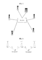
- FIG. 2 is a diagram illustrating an example of a multi-node system (DAS) to which the present invention is applied.
- DAS multi-node system
- FIG. 2 illustrates a distributed multi-node system (DMNS) of the DAS.
- DMNS distributed multi-node system
- a plurality of nodes spaced apart from one another in a certain local area are connected to one base station or base station controller through a cable or dedicated line.
- one controller controls transmission and reception through all the nodes located within the certain local area.
- FIG. 2 illustrates that one controller controls transmission and reception through all the nodes located within the certain local area, it is not required that nodes, which perform cooperative transmission, should be controlled by only one controller.
- the present invention may be applied to the case where nodes controlled by different base stations or base station controllers perform cooperative transmission.
- one or more base stations or base station controllers which are connected to the plurality of nodes, may control the plurality of nodes to transmit or receive signals to or from the user equipment through some of the plurality of nodes at the same time.
- the multi-node systems are different from a single node system (for example, CAS, MIMO system of the related art, relay system of the related art, and repeater system of the related art) in that the plurality of nodes provide communication services to the user equipment on a predetermined time-frequency resource. Accordingly, the embodiments of the present invention in respect of a method for performing cooperative transmission using all or some of a plurality of nodes may be applied to various multi-node systems.
- the nodes refer to an antenna group spaced apart from another node
- the embodiments of the present invention which will be described later, may be applied to the case where the nodes mean a random antenna group regardless of spacing.
- the antenna group may be replaced with an antenna port, antenna pattern and antenna configuration.
- FIG. 3 is a diagram illustrating an example of cooperative transmission between nodes to which the present invention is applied.
- the multi-node system may have more excellent throughput than non-cooperative transmission in accordance with efficient interference avoidance or removal scheme in such a manner that multiple nodes transmit and receive data to common user equipment(s) in cooperation with one another at the same time or share information of a node that provides more interference.
- feedback information of the user equipment that is, channel state information transmitted from the user equipment
- This feedback information may be divided into two types in accordance with methods of cooperative transmission between the nodes.
- the feedback information of the user equipment according to the methods of cooperative transmission between the nodes will be described in detail.
- joint processing or multi-BS joint processing scheme is defined as a transmission scheme for transmitting data from a plurality of nodes to a user equipment in one resource region.
- JP joint processing or multi-BS joint processing
- the user equipment obtains a channel value of each node and feeds channel state information back on the basis of the channel value.
- the channel state information may include Channel Quality Indicator (CQI), Precoding Matrix Indicator (PMI), Rank Indicator (RI), etc.
- CQI represents a signal to interference-noise ratio, and may be expressed as a power level or modulation and coding (MCS) level.
- MCS modulation and coding
- the PMI indicates a vector which is an element of a codebook of the user equipment, or index of matrixes.
- the user equipment 1 may acquire channel values G1 and H1 by measuring channels of the node 1 and the node 2.
- the user equipment may obtain a precoding vector or precoding matrix having maximum received signal strength on the basis of the channel values G1 and H1.
- the user equipment 1 obtains the value of V1 having maximum
- the precoding vector (for example, V1 and W1) is quantized to a value of 3 bits to 6 bits, and is expressed as PMI. Meanwhile, there is difficulty in representing a phase difference between the nodes by using PMI only due to limitation of quantization.
- a phase may be represented by e j ⁇ , its ⁇ value may be defined previously, and index thereof may be fed back as CPMI.
- PMI and CPMI of the respective cooperative transmission candidate nodes may be transmitted.
- CQI and RI may be transmitted together with PMI and CPMI.
- the user equipment calculates PMI and CPMI of each node that performs JP, and feeds back the calculated PMI and CPMI, and may feed back one CQI for reference when the cooperative transmission candidate nodes perform JP.
- the user equipment may not transmit rank indicator (RI).
- Coordinated Scheduling Coordinated Beamforming or Single-BS Precoding with Multi-BS Coordination
- CS Coordinated Scheduling, Coordinated Beamforming or Single-BS Precoding with Multi-BS Coordination
- the serving node if the user equipment measures a channel of an interference node, calculates PMI having the greatest interference or the smallest interference, and transfers the calculated PMI to a serving node, the serving node notifies the interference node of the calculated PMI, whereby the interference node may be restricted to use the PMI having the greater interference or may be led to use the PMI having the smaller interference.
- the PMI has been described as an example, it will be apparent that the CS may equally be applied to all kinds of the channel state information.
- the channel state information is fed back from the user equipment to the network formed for cooperative transmission by the nodes.
- a specific node may not transmit and receive data on the basis of the channel state information fed back from the user equipment.
- JP is fed back to the specific node
- the specific node may perform single transmission to a single node without performing JP as a result of scheduling.
- feedback is performed by assuming that N number of nodes perform cooperative transmission
- cooperative transmission may be performed by the nodes less than N.
- the nodes which do not perform JP may transmit data to another user equipment by using the same resource at the same time. In this case, the signal may act as interference to the user equipment.
- the embodiment of the present invention suggests that the user equipment feeds back a plurality of kinds of channel state information to the network, that is, each node, for flexible scheduling of the network.
- the present invention will be described on the basis of the PMI of the channel state information, the present invention is not limited to the PMI and may similarly be applied to various kinds of channel state information.
- cooperative transmission candidate nodes of the user equipment 1 are the node 1 and the node 2
- cooperative transmission candidate nodes of the user equipment 2 are the node 2 and the node 3.
- the user equipment 1 and the user equipment 2 feed PMI and CPMI of the respective candidate nodes and other required information back by assuming JP.
- the node 2 if the node 2 transmits data to the user equipment 1, it acts as interference to the user equipment 2.
- the network may perform a control operation so as not to transmit data to the user equipment 2
- the network may perform a control operation so that only the node 3 transmits data to the user equipment 2.
- the node 3 cannot provide optimized throughput to the user equipment 2 when transmitting data to the user equipment 2. Accordingly, the user equipment 2 is required to provide additional PMI in addition to the PMI and/or CPMI for the node 3, which is obtained by assuming JP of the node 2 and the node 3.
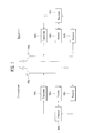
- FIG. 4 is a diagram illustrating a procedure of transmitting channel state information in accordance with the first embodiment of the present invention.
- FIG. 4 illustrates a procedure of transmitting PMI.
- some of cooperative transmission candidate nodes for a specific user equipment cannot perform JP. If some of the cooperative transmission candidate nodes cannot perform JP, as shown in FIG. 3 , the corresponding node may act as an interference node for the user equipment as described above.
- the network formed by the nodes requests the user equipment to report PMI for the cooperative transmission candidate nodes (S110).
- the user equipment calculates PMI for each cooperative transmission candidate node (S120), and transmits the calculated PMI to the network (S130).
- the network transmits information of the corresponding node, that is, the node, which acts as the interference node to the user equipment, and PMI of the corresponding node to the user equipment (S 140).
- the user equipment may again calculate PMI of the cooperative transmission candidate nodes except for the node, which acts as the interference node, on the basis of the information received from the network (S 150), and may transmit the calculated PMI to the network (S160). For example, in FIG.
- the user equipment 1 may calculate W1' which is new PMI satisfying H1W1' ⁇ G1V2 and/or max
- the cooperative transmission candidate nodes may transmit data to the user equipment by using each PMI which is received (S 170).
- FIG. 5 is a diagram illustrating a procedure of transmitting channel state information in accordance with the second embodiment of the present invention.
- the network may transmit information on cooperative transmission candidate nodes and interference candidate nodes to the user equipment (S210).
- the information on the interference candidate nodes includes information as to which node of the cooperative transmission candidate nodes acts as the interference node and PMI used by the corresponding interference node.
- the user equipment 1 is notified from the network that the node 1 and the node 2 are the cooperative transmission candidate nodes and the node 2 is the interference node.
- the interference candidate node may be selected from the cooperative transmission candidate nodes.
- the network may first notify a set of the cooperative transmission candidate nodes, and may transmit the interference candidate node of the cooperative transmission candidate nodes by using a bitmap, etc. Since the interference candidate node may be the cooperative transmission candidate node for another user equipment, it may be referred to as a shared node.
- the user equipment may calculate the first PMI and/or the first CPMI for each of the cooperative transmission candidate nodes by assuming JP of the cooperative transmission candidate nodes, on the basis of the received information (S220), regard the interference candidate node as the interference node, and calculate the second PMI and/or the second CPMI for each of the cooperative transmission candidate nodes except for the interference node (S230). For example, in FIG.
- the user equipment 1 may calculate W1' which is PMI satisfying H1W1' ⁇ G1(:,k1, k2, ...., kn) and/or max
- G1(:,k1, k2, ..., kn) is the matrix configured by k1,k2,...,knth columns of G1.
- the column having great norm is used when a part of the columns of G1 is used.
- Each column represents each layer of rank n (n is a natural number). In other words, using a part of the columns means using a part of layers of rank.
- the part of the layers means the layer having the best throughput of columns of great norm, that is, H1W1' ⁇ G1(:k1), H1W1' ⁇ G1(:k2), ..., H1W1' ⁇ G1(:kn).
- the user equipment 1 may calculate PMI1, PMI2, and CPMI by assuming JP for the node 1 and the node 2, which are the cooperative transmission candidate nodes, and may additionally calculate PMI1' by regarding the node 2, which is the interference candidate node, as the interference node. Afterwards, the user equipment may transmit the calculated first PMI and/or first CPMI and the second PMI and/or second CPMI to the network.
- the user equipment which has received the information as to that the node 1 of the cooperative transmission candidate nodes node 1, node 2 and node 3 is the interference candidate node, calculates PMI and/or CPMI by assuming that the node 1, the node 2 and the node 3 perform JP, and feeds the calculated PMI and/or CPMI back to each node (for example, PMI1, PMI2, PMI3, CPMI2, CPMI3).
- the user equipment may calculate PMI and/or CPMI by assuming that the node 1 acts as the interference node and the node 2 and the node 3 perform JP, and may additionally transmit the calculated PMI and/or CPMI to each node (for example, PMI2', PMI3', CPMI2', CPMI3').
- the network may additionally notify the user equipment of layer relation between the interference candidate nodes. For example, in addition to the information as to that the node 1 and the node 2 are the interference candidate nodes, the network may additionally notify that the node 1 and the node 2 form one layer (or stream) or each of the node 1 and the node 2 forms one layer.
- the user equipment calculates CQI by regarding the interference candidate node as the interference node. For example, if the user equipment 1 receives information as to that the node 1 and the node 2 are the cooperative transmission candidate nodes and the node 1 is the interference node, from the network, the user equipment calculates the first CQI by assuming that the node 1 and the node 2 perform JP, and additionally calculates the second CQI by assuming that the node 1 acts as the interference node and receives data from the node.
- RS demodulation reference signal
- r represents the received signal
- W represents the precoder for the node 2
- V represents the precoder for the node 3
- X represents an interference signal occurring in the node 2
- S represents data transmitted from the node 3
- n represents other interference and noise.
- the user equipment may receive W from the network, or may assume a random precoder.
- the random precoder may correspond to a random precoding vector or matrix within the codebook stored in the user equipment.
- H2W may correspond to the column having the greatest norm among the columns of H2.
- FIG. 6 is a diagram illustrating a procedure of transmitting channel state information in accordance with the third embodiment of the present invention.
- FIG. 6 illustrates the procedure of transmitting PMI.
- PMI for all the antenna ports may be defined.
- the network may transmit information indicating that four antenna ports correspond to cooperative transmission candidate antenna ports, to the user equipment (S310). This information may be transmitted through a reference signal.
- the network may notify the user equipment of the information through a channel state information reference signal (CSI-RS) corresponding to four antenna ports.
- CSI-RS channel state information reference signal
- the network may additionally notify the user equipment of interference candidate antenna ports, which may act interference antennas, among four cooperative transmission candidate antenna ports (S310). For example, the network may notify the user equipment that antenna port k1 and antenna port k2 of the four antenna ports correspond to the interference candidate antenna ports, which may provide interference signals.
- the user equipment may obtain or calculate the first PMI from 4Tx codebook by assuming that four antenna ports are the cooperative transmission antenna ports (S320), and may assume that the antenna ports k1 and k2 of the four antenna ports are interference antenna ports and obtain or calculate the second PMI from 2Tx codebook with respect to the other antenna ports except for the interference antenna ports (S330).
- the user equipment may feed the calculated first PMI and second PMI back to the network (S340).
- the user equipment may command the user equipment to calculate the first PMI for four antenna ports and the second PMI assuming cooperative transmission of the antenna ports k3 and k4 and feed the calculated first PMI and second PMI back.
- the user equipment may obtain the first PMI from the 4Tx codebook with respect to four antenna ports and obtain the second PMI from the 2Tx codebook with respect to the antenna ports k3 and k4.
- the antenna port may be replaced with the terms such as antenna, CSI-RS port, antenna configuration, and antenna pattern, as mentioned above.
- the operation of the user equipment, which calculates PMI may be replaced with the operation for calculating the precoding vector/matrix, and the operation of the user equipment, which obtains CPMI, may be replaced with the operation for calculating a phase control value.
- the channel state information for the specific node may be measured using a reference signal (RS) transmitted from the specific node to all bands.
- a reference signal For example, a cell specific reference signal and a channel state information reference signal (CSI-RS) may be used for calculation of the channel state information.
- the reference signal may be referred to as other terms such as pilot, preamble, and midamble.
- Signals used by the user equipment to estimate and measure the channel state may be the reference signals applied to the present invention regardless of their title.
- groups of time-frequency resources which may transmit the reference signals within the resource region defined by a plurality of time-frequency resources, may be defined previously.
- the method for transmitting and receiving channel state information according to the present invention may industrially be applicable to various wireless communication systems such as 3GPP LTE system, 3GPP LTE-A system and IEEE 802 system.
Landscapes
- Engineering & Computer Science (AREA)
- Computer Networks & Wireless Communication (AREA)
- Signal Processing (AREA)
- Physics & Mathematics (AREA)
- Mathematical Physics (AREA)
- Mobile Radio Communication Systems (AREA)
Applications Claiming Priority (3)
| Application Number | Priority Date | Filing Date | Title |
|---|---|---|---|
| US201161452173P | 2011-03-14 | 2011-03-14 | |
| US201161453133P | 2011-03-16 | 2011-03-16 | |
| PCT/KR2012/000520 WO2012124892A1 (ko) | 2011-03-14 | 2012-01-20 | 채널상태정보 송수신 방법 및 송수신 장치 |
Publications (2)
| Publication Number | Publication Date |
|---|---|
| EP2688220A1 true EP2688220A1 (de) | 2014-01-22 |
| EP2688220A4 EP2688220A4 (de) | 2014-08-20 |
Family
ID=46830923
Family Applications (1)
| Application Number | Title | Priority Date | Filing Date |
|---|---|---|---|
| EP12757685.8A Withdrawn EP2688220A4 (de) | 2011-03-14 | 2012-01-20 | Verfahren zum senden und empfangen von kanalstatusinformationen und sendevorrichtung dafür |
Country Status (3)
| Country | Link |
|---|---|
| US (1) | US9167465B2 (de) |
| EP (1) | EP2688220A4 (de) |
| WO (1) | WO2012124892A1 (de) |
Families Citing this family (9)
| Publication number | Priority date | Publication date | Assignee | Title |
|---|---|---|---|---|
| US8891472B2 (en) * | 2011-10-04 | 2014-11-18 | Samsung Electronics Co., Ltd | Method and apparatus for reporting channel state information in a wireless communication system |
| US9049730B2 (en) * | 2011-11-14 | 2015-06-02 | Qualcomm Incorporated | Uplink data transmission with interference mitigation |
| US8953478B2 (en) * | 2012-01-27 | 2015-02-10 | Intel Corporation | Evolved node B and method for coherent coordinated multipoint transmission with per CSI-RS feedback |
| WO2014069941A1 (ko) * | 2012-11-02 | 2014-05-08 | 삼성전자 주식회사 | 통신 시스템에서 간섭 측정을 위한 방법 및 그 장치 |
| KR102052420B1 (ko) | 2012-11-02 | 2019-12-05 | 코란씨, 엘엘씨 | 통신 시스템에서 간섭 측정을 위한 방법 및 그 장치 |
| RU2639949C2 (ru) | 2013-06-05 | 2017-12-25 | Эл Джи Электроникс Инк. | Способ и устройство для передачи информации о состоянии канала в системе беспроводной связи |
| CN107708196B (zh) * | 2016-08-09 | 2020-12-01 | 上海诺基亚贝尔股份有限公司 | 通信方法、网络设备和终端设备 |
| CN108012274B (zh) * | 2016-11-01 | 2019-10-29 | 上海朗帛通信技术有限公司 | 一种被用于范围扩展的ue、基站中的方法和设备 |
| US10833742B2 (en) | 2018-08-10 | 2020-11-10 | At&T Intellectual Property I, L.P. | Determining channel state information in advanced networks |
Family Cites Families (3)
| Publication number | Priority date | Publication date | Assignee | Title |
|---|---|---|---|---|
| KR20060060382A (ko) * | 2004-11-30 | 2006-06-05 | 삼성전자주식회사 | 직교 주파수 분할 다중 접속 방식을 사용하는 이동 통신시스템에서 채널 정보 송/수신을 위한 시스템 및 방법 |
| WO2007111266A1 (ja) * | 2006-03-24 | 2007-10-04 | Matsushita Electric Industrial Co., Ltd. | 無線通信端末装置及び無線通信基地局装置 |
| KR101478843B1 (ko) * | 2009-01-22 | 2015-01-05 | 엘지전자 주식회사 | 협력적 다중 셀 무선통신 시스템에서 데이터를 송신하는 방법 |
-
2012
- 2012-01-20 EP EP12757685.8A patent/EP2688220A4/de not_active Withdrawn
- 2012-01-20 US US14/004,965 patent/US9167465B2/en not_active Expired - Fee Related
- 2012-01-20 WO PCT/KR2012/000520 patent/WO2012124892A1/ko not_active Ceased
Also Published As
| Publication number | Publication date |
|---|---|
| US20130343220A1 (en) | 2013-12-26 |
| EP2688220A4 (de) | 2014-08-20 |
| WO2012124892A1 (ko) | 2012-09-20 |
| US9167465B2 (en) | 2015-10-20 |
Similar Documents
| Publication | Publication Date | Title |
|---|---|---|
| US11044065B2 (en) | Method and apparatus for transmitting and receiving feedback information in mobile communication system using multiple antennas | |
| US10778348B2 (en) | Interference measurements and channel state information feedback for multi-user multiple-in multiple-out | |
| US10771118B2 (en) | Channel state measurement method and apparatus | |
| EP2918095B1 (de) | Verfahren zur rückmeldung von kanalstatusinformationen in einem drahtlosen kommunikationssystem und vorrichtung dafür | |
| EP3289817B1 (de) | System und verfahren für mehrstufige strahlgeformte nicht-orthogonale vielfachzugriffskommunikationen | |
| US9438395B2 (en) | Method for feeding back channel state information in wireless communication system and apparatus therefor | |
| US9167465B2 (en) | Method for transceiving channel state information and transceiving device | |
| EP3857785B1 (de) | Begrenzung der leistungssteuerungskonfigurationen eines klangreferenzsignals | |
| EP2658155B1 (de) | Verfahren zur berichterstattung von kanalstatusinformationen in einem drahtlosen kommunikationssystem und vorrichtung dafür | |
| US11923933B2 (en) | Operating communication devices | |
| KR101060857B1 (ko) | Mimo 통신 시스템에서의 데이터 전송 방법 및 장치 | |
| US10396955B2 (en) | Method for transmitting and receiving reference signal in wireless communication system | |
| EP3382903A1 (de) | Verfahren zur übertragung und zum empfang von kanalstatusinformationen in einem drahtloskommunikationssystem und vorrichtung dafür | |
| US20150036610A1 (en) | Method for providing feedback of channel state information in wireless communication system and apparatus for same | |
| US20180083681A1 (en) | A CSI Report Framework for Enhanced Separate Dimension Feedback | |
| US20150304010A1 (en) | Channel state information reporting method, user equipment, and base station | |
| EP3399661A1 (de) | Verfahren zur csi-berichterstattung in einem drahtloskommunikationssystem und vorrichtung dafür | |
| EP2670059B1 (de) | Verfahren und benutzervorrichtung zur übertragung von kanalstatusinformationen sowie verfahren und basisstation zum empfangen von kanalstatusinformationen | |
| KR20250009994A (ko) | Csi 참조 자원 및 보고 창을 위한 방법 및 장치 | |
| US20140023033A1 (en) | Method and apparatus for transceiving channel status information and transceiver |
Legal Events
| Date | Code | Title | Description |
|---|---|---|---|
| PUAI | Public reference made under article 153(3) epc to a published international application that has entered the european phase |
Free format text: ORIGINAL CODE: 0009012 |
|
| 17P | Request for examination filed |
Effective date: 20130920 |
|
| AK | Designated contracting states |
Kind code of ref document: A1 Designated state(s): AL AT BE BG CH CY CZ DE DK EE ES FI FR GB GR HR HU IE IS IT LI LT LU LV MC MK MT NL NO PL PT RO RS SE SI SK SM TR |
|
| DAX | Request for extension of the european patent (deleted) | ||
| A4 | Supplementary search report drawn up and despatched |
Effective date: 20140723 |
|
| RIC1 | Information provided on ipc code assigned before grant |
Ipc: H04W 24/10 20090101ALI20140717BHEP Ipc: H04B 7/02 20060101ALI20140717BHEP Ipc: H04B 7/26 20060101ALI20140717BHEP Ipc: H04B 7/04 20060101AFI20140717BHEP Ipc: H04B 7/06 20060101ALI20140717BHEP |
|
| STAA | Information on the status of an ep patent application or granted ep patent |
Free format text: STATUS: THE APPLICATION HAS BEEN WITHDRAWN |
|
| 18W | Application withdrawn |
Effective date: 20181123 |