EP2688471B1 - Système et procédé d'imagerie par spectroscopie par résonance magnétique - Google Patents
Système et procédé d'imagerie par spectroscopie par résonance magnétique Download PDFInfo
- Publication number
- EP2688471B1 EP2688471B1 EP12760705.9A EP12760705A EP2688471B1 EP 2688471 B1 EP2688471 B1 EP 2688471B1 EP 12760705 A EP12760705 A EP 12760705A EP 2688471 B1 EP2688471 B1 EP 2688471B1
- Authority
- EP
- European Patent Office
- Prior art keywords
- magnetic resonance
- compartment
- interest
- csi
- spatial
- Prior art date
- Legal status (The legal status is an assumption and is not a legal conclusion. Google has not performed a legal analysis and makes no representation as to the accuracy of the status listed.)
- Active
Links
Images


Classifications
-
- G—PHYSICS
- G01—MEASURING; TESTING
- G01R—MEASURING ELECTRIC VARIABLES; MEASURING MAGNETIC VARIABLES
- G01R33/00—Arrangements or instruments for measuring magnetic variables
- G01R33/20—Arrangements or instruments for measuring magnetic variables involving magnetic resonance
- G01R33/44—Arrangements or instruments for measuring magnetic variables involving magnetic resonance using nuclear magnetic resonance [NMR]
- G01R33/46—NMR spectroscopy
-
- G—PHYSICS
- G01—MEASURING; TESTING
- G01R—MEASURING ELECTRIC VARIABLES; MEASURING MAGNETIC VARIABLES
- G01R33/00—Arrangements or instruments for measuring magnetic variables
- G01R33/20—Arrangements or instruments for measuring magnetic variables involving magnetic resonance
- G01R33/44—Arrangements or instruments for measuring magnetic variables involving magnetic resonance using nuclear magnetic resonance [NMR]
- G01R33/48—NMR imaging systems
- G01R33/483—NMR imaging systems with selection of signals or spectra from particular regions of the volume, e.g. in vivo spectroscopy
- G01R33/485—NMR imaging systems with selection of signals or spectra from particular regions of the volume, e.g. in vivo spectroscopy based on chemical shift information [CSI] or spectroscopic imaging, e.g. to acquire the spatial distributions of metabolites
-
- A—HUMAN NECESSITIES
- A61—MEDICAL OR VETERINARY SCIENCE; HYGIENE
- A61B—DIAGNOSIS; SURGERY; IDENTIFICATION
- A61B5/00—Measuring for diagnostic purposes; Identification of persons
- A61B5/05—Detecting, measuring or recording for diagnosis by means of electric currents or magnetic fields; Measuring using microwaves or radio waves
- A61B5/055—Detecting, measuring or recording for diagnosis by means of electric currents or magnetic fields; Measuring using microwaves or radio waves involving electronic [EMR] or nuclear [NMR] magnetic resonance, e.g. magnetic resonance imaging
-
- G—PHYSICS
- G01—MEASURING; TESTING
- G01R—MEASURING ELECTRIC VARIABLES; MEASURING MAGNETIC VARIABLES
- G01R33/00—Arrangements or instruments for measuring magnetic variables
- G01R33/20—Arrangements or instruments for measuring magnetic variables involving magnetic resonance
- G01R33/44—Arrangements or instruments for measuring magnetic variables involving magnetic resonance using nuclear magnetic resonance [NMR]
- G01R33/48—NMR imaging systems
- G01R33/483—NMR imaging systems with selection of signals or spectra from particular regions of the volume, e.g. in vivo spectroscopy
Definitions
- the field of the currently claimed embodiments of this invention relates to systems and methods of spatially localized magnetic resonance spectroscopy.
- the present invention provides a method and a system according to the independent claims. Further preferred embodiments of the present invention are defined in the depending claims.
- Speed and signal-to-noise ratio are central requirements for localized magnetic resonance spectroscopy (MRS) of low-concentration metabolites.
- Matching voxels to anatomical compartments a priori yields better SNR than the spectra created by summing signals from constituent chemical-shift-imaging (CSI) voxels post-acquisition.
- CSI chemical-shift-imaging
- SLAM linear algebraic modeling
- SLAM CSI surface coil phosphorus MRS in phantoms, the human leg and the heart on a 3T clinical scanner. Its SNR performance, accuracy, sensitivity to registration errors and inhomogeneity, are evaluated. Compared to one-dimensional CSI, SLAM yielded quantitatively the same results 4-times faster in 24 cardiac patients and healthy subjects, and 45% higher cardiac SNR when applied pro-actively to 6 additional subjects.
- SLAM can be further extended according to an embodiment of the current invention with fractional phase-encoding gradients that minimize intra-compartmental contamination, and optionally inter-compartmental contamination, and optionally optimize SNR.
- fractional-SLAM fSLAM
- SLAM and fSLAM are simple to implement and reduce minimum scan times for CSI, which otherwise limits scan-time reductions achievable with higher SNR and field strengths.
- Scan-time and signal-to-noise ratio are major problems for in vivo spatially localized magnetic resonance spectroscopy (MRS) of low-concentration metabolites.
- MRS magnetic resonance spectroscopy
- the SNR/voxel is now 5 per acquisition because noise is independent of voxel size [1].
- Phase-encoding is equivalent to averaging, so after 4 gradient steps to encode the same volume, the SNR per voxel is 10.
- Adding the 4 signals to make a V-sized voxel now yields an SNR of 20, again because of the n rule. This compares to 40 from the first experiment.
- the SNR for the same scan-time and voxel size is doubled in the first experiment, just by pre-selecting the correct voxel size to start with [1].
- SRF integrated spatial response function
- Prior phase-encoding gradient based MRS localization methods such as SLIM[3], GSLIM[4] and SLOOP[5], could realize the g-fold SNR gain if the desired compartments were prescribed from scout MRI prior to acquisition, and if an appropriately SNR-optimized gradient set were then applied.
- SLIM the compartment's signal is modeled as the integral of phase-encoded signal contributions in each compartment, assumed homogeneous. The approach is prone to inter- and intra-compartmental errors when metabolite distributions are non-uniform between [6] and within each compartment, and as the number of phase-encoding gradient steps are reduced.
- GSLIM[4] and SLOOP[5] were introduced to minimize the inter-compartmental errors.
- GSLIM does this by applying non-Fourier, generalized series modeling to the SLIM result[4, 6].
- SLOOP minimizes the inter-compartmental error by optimizing the SRF for the desired compartment, ideally by specifically tailoring the phase-encoding gradient set for the acquisition[5].
- Several other proposed improvements add constraints to deal with inhomogeneity in the main (B 0 ) field[7-9], registration errors[9], and multi-element receivers[10].
- SLAM linear algebraic modeling
- the SLAM pulse sequence differs in that the number of phase-encoding steps is essentially C, and they are always selected from the center of the integer-stepped k-space of CSI where SNR is highest. Other than determining the number, C, the need for image-guided gradient optimization, prescription and implementation at the scanner-side prior to acquisition, is thus avoided.
- SLAM g-fold SNR gains of 30-200% SNR are demonstrated in 3T phosphorus ( 31 P) studies of the human leg and heart in vivo, compared to conventional[17-22] one-dimensional (1D) CSI spectra from the same net volume and scan-time.
- phase-encoding gradients are pro-actively optimized at the scanner-side to minimize intra-compartmental errors produced by nonuniform signal distributions, and optionally minimize the intercompartmental leakage and/or maximize SNR. Intra-compartmental errors have not been addressed in prior methods [3-5].
- An example of fSLAM according to an embodiment of the current invention is demonstrated in pro-active human cardiac 31 P studies.
- FIG. 1 is a schematic illustration of a magnetic resonance spectroscopy and imaging (MRSI) system 100 according to an embodiment of the current invention.
- the MRSI system 100 includes a magnetic resonance scanner 101, a data storage unit 108, and a data processing unit 109.
- Magnetic resonance scanner 101 has a main magnet 105 providing a substantially uniform main magnetic field B 0 for a subject (or object) 102 under observation on scanner bed 103, a gradient system 106 providing a perturbation of the main magnetic field B 0 to encode spatial information of the constituent molecules of subject 102 under observation, and a radio-frequency (RF) coil system 107 to transmit electromagnetic waves and to receive magnetic resonance signals from subject 102.
- RF radio-frequency
- Data storage unit 108 may be, for example, a hard disk drive, a network area storage (NAS) device, a redundant array of independent disks (RAID), a flash drive, an optical disk, a magnetic tape, a magneto-optical disk, etc.
- NAS network area storage
- RAID redundant array of independent disks
- flash drive an optical disk
- magnetic tape a magnetic tape
- magneto-optical disk etc.
- the data storage unit 108 is not limited to these particular examples. It can include other existing or future developed data storage devices without departing from the scope of the current invention.
- the data processing system 109 is in communication with magnetic resonance scanner 101 to receive magnetic resonance signals for forming magnetic resonance images of subject 102.
- Data processing system 109 may be partially or totally incorporated within a structure housing magnetic resonance scanner 101.
- Data processing system 109 may be partially or totally incorporated in a workstation that is structurally separate from and in communication with magnetic resonance scanner 101.
- Data processing system 109 may be incorporated in a workstation that is structurally separate from and in communication with magnetic resonance scanner 101.
- An operator 113 may interact with the MRSI system 100 with input/output device 112.
- the data processing system 109 is configured to receive a magnetic resonance image of the object; display the magnetic resonance image to permit identification of a plurality C of compartments that generate magnetic resonance spectroscopy signals in the object and that includes at least one compartment of interest; segment in at least one spatial dimension the magnetic resonance image of the object into the C compartments; receive magnetic resonance spectroscopy signals from the object corresponding to the magnetic resonance image by applying a plurality M' of phase encodings in at least one spatial dimension, where M' ⁇ C; calculate a spatially localized magnetic resonance chemical shift spectrum from at least one compartment of interest; and provide a spatially localized magnetic resonance spectrum substantially equal to the spatial average of magnetic resonance chemical shift spectra from the at least one compartment of interest.
- the calculating of the spatially localized magnetic resonance chemical shift spectrum from the at least one compartment of interest according to the present invention uses a linear algebraic method.
- the magnetic resonance spectroscopy and imaging scanner is further configured to permit identification and segmentation of the C compartments prior to receiving the magnetic resonance spectroscopy signals from the object.
- the magnetic resonance spectroscopy and imaging scanner is further configured to optimize the M' phase encodings for the spatial selection in the at least one compartment of interest, and optionally for the SNR.
- the at least one of the plurality M' of phase encodings is a non-integer multiple of a smallest non-zero phase encoding.
- the data processing system is further configured to perform optimization of the spatial selection of the at least one compartment of interest by minimization of erroneous signals arising from non-uniform magnetic resonance spectroscopy signal distributions arising within the compartment of interest.
- the data processing system may further be configured to perform optimization of the signal-to-noise ratio in the at least one compartment of interest, and/or minimization of at least one magnetic resonance spectroscopy signal arising from outside of the compartment of interest.
- the plurality M' of phase encodings can be provided by including a metric that optimizes both the signal-to-noise ratio and the spatial selection in the at least one compartment of interest.
- the at least one spatial dimension is one of two spatial dimensions or three spatial dimensions
- the plurality M' of phase encodings includes two or three subsets of phase encodings that are applied in the two or the three spatial dimensions, respectively.
- the number of phase encodings provided in each of the subset of phase encodings is greater than or equal to the number of compartments generating magnetic resonance spectroscopy signals that are segmented in the corresponding spatial dimensions of the object.
- the at least one compartment of interest can be a plurality of compartments of interest.
- Each row of the known signal matrix, S M ⁇ N , on the left side of the equation is an N-point array, where N is the number of time-domain data points.
- the first matrix on the right side is the phase-encoding FT operator (PE), and each term of the unknown spectral matrix, ⁇ , is also an N-point array.
- PE phase-encoding FT operator
- the goal of the CSI experiment is to reconstruct the M unknown spectra in matrix ⁇ of Eq. (3), from the M known signals (S) acquired with M different phase-encodes.
- S M known signals
- ⁇ has just C ⁇ M MRS compartments of interest, as well as the spatial position of each compartment. Theoretically, only C measurements with C phase-encoding steps are needed to unambiguously solve ⁇ and reconstruct the C spectra.
- Eq. (5) is now over-determined and can be solved with three phase-encoding rows.
- the minimum number of required phase-encoding steps is reduced from 4 to 3.
- Steps 1-5 are performed with Steps 1-5 as follows:
- the choice of the M' phase-encoding steps need not be limited to the original basis set of M CSI steps corresponding to integer k's in Eq. (3).
- the M' phase-encoding gradients can be chosen to optimize desired properties of the reconstruction. For example, as we now show, the gradients can be optimized to maximize the SNR, and/or minimize the inter-compartmental signal contamination, and/or minimize the intra-compartmental error due to nonuniform signal sources. This effectively involves allowing for fractional k's in the CSI Eq. (3), with all other experimental parameters left unchanged. Unlike SLAM, this fractional SLAM method, denoted fSLAM, does require scanner-side gradient optimization and prescription.
- SNR i CSI L i / M 1 / 2 ⁇ ⁇ C ⁇ N CSI i / ⁇
- L i is the size of the i th compartment with average spectrum ⁇ C ⁇ N CSI i .
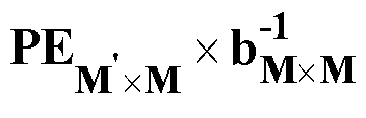
- the first part PE M ′ ⁇ M ⁇ b M ⁇ M - 1 ⁇ b M ⁇ M ⁇ ⁇ M ⁇ N avg satisfies the ideal homogeneity assumption of SLAM
- the second part ( PE M ′ ⁇ M ⁇ ⁇ M ⁇ N inhom ) is the source of signal leakage and errors.
- w ij is the weight of inter-compartment leakage from the j th compartment into the i th compartment.
- the w ij can reflect, for example, intrinsic differences in metabolite concentrations between compartments.
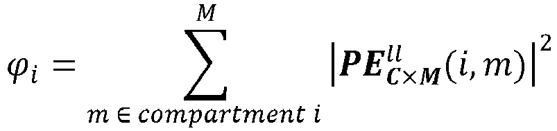
- ⁇ i ⁇ m ⁇ compartment i M w ii ⁇ PE C ⁇ M ll i m 2
- w ii is the weight of intra-compartment error in the i th compartment.
- ⁇ i ⁇ i + ⁇ i / I cond for the i th compartment.
- the fSLAM experiment is performed using the same Steps 1-5 as the SLAM protocol ( Figure 2 ) except that the phase-encoding gradients in Step 2 are obtained by minimizing either the SNR cost-function in Eq. (12) or the error cost-function in Eq. (18).
- the different optimizations will result in different sets of phase-encoding gradients. If a gradient set optimized for both SNR and minimum error is being sought, minimization of the sum of the cost-functions in Eqs. (12) and (18) cannot be used because their scales differ. Instead, minimization of a weighted sum of the ratio of cost functions for fSLAM to those for SLAM can suffice. The choice of the weighting will depend on the application and error tolerance.
- the phase-encoding gradients in Step 2 are typically fractional.
- PE C ⁇ M ll i is derived from b and therefore requires knowledge of compartment location and size, and the choice of gradients is not constrained to the CSI integer gradient steps, optimization and selection of the fSLAM gradient set must be performed scanner-side as part of the MRS set-up in order to achieve any SNR advantage compared to the summed CSI spectra from the same compartment volume.
- the first integral in Eq. (21) is the chest to heart leakage, ⁇ .
- the right hand side of the last line of Eq. (22) is the upper limit of the contamination of the heart spectrum from chest signal.
- a random inhomogeneity of ⁇ 15% (30% total) in the resultant signal was then simulated for both scenarios.
- the mean signal was determined for each compartment by adding signals from the corresponding voxels of the full CSI set to serve as a reference. Then, white noise was added such that the SNR in the heart compartment was 20.
- the mean error and the SD of the error were determined after 1000 Monte Carlo simulation runs.
- SLIM reconstruction was performed as prescribed[3], by integrating the phase-encoding coefficients over the 3-compartment model of heart, chest and 'other' and generating a 4x3 ⁇ G'-matrix[3].
- the mean ( ⁇ SD) % error between the reconstructed signal and the true or the CSI result was calculated for 1000 runs.
- the SNR was measured relative to the compartment average SNR of the 16-voxel 1D CSI (Eq. (13)), using the M' 3 to 16 central k-space acquisitions for SLAM, and fractional (low k-space) phase-encodes for fSLAM.
- SRF h was calculated from Eq. (19) for 4-step SLAM, 4-step fSLAM, 16-step CSI and 4-step CSI (zero-filled to 16 steps) for the 3-voxel chest/ 4-voxel heart model.
- the upper bound of chest contamination of the heart spectrum for the four cases was calculated from Eq. (22) assuming an effective chest to heart ratio of 4 and an intra-compartmental inhomogeneity of ⁇ 15% (30% total) for the chest.
- 31 P 1D CSI, SLAM, and fSLAM were implemented in a 3T Philips Achieva MRI/MRS system on phantoms, the human leg, and the human heart.
- the phantom studies were done with a 14-cm diameter single loop transmit/receive coil, and the human studies used a 17-cm/11-cm diameter dual loop transmit and a 8-cm diameter single loop receive 31 P coil set described previously[22]. All human studies were approved by the Johns Hopkins Medicine Institutional Review Boards and all participants provided informed consent.
- the individual CSI spectra from all of the volume elements constituting each compartment were co-added post-acquisition for all comparisons of spectra from the equivalent volumes reconstructed using SLAM and fSLAM.
- FSC frequency-sweep-cycled
- AHP adiabatic half passage
- the leg was studied with the 300 mM H 3 PO 4 disk phantom on top to create an additional compartment.
- Spectra were fit by the circle-fit method[25] to provide a quantitative comparison of PCr and ⁇ -ATP peak areas measured by SLAM with those from conventional CSI (the localization and spectral analysis method are independent). Spectra were exponential-filtered (15-Hz line-broadening) and zero-filled 4 times to 2048 points.
- SLAM used the same 4 middle k-space phase-encoding steps for each exam, repeated four times for the same total scan-time as CSI.
- fSLAM phase-encoding employed 4, typically-fractional gradient steps, specifically optimized for minimum compartmental leakage in the heart compartment for each volunteer, after manual segmentation of the scout MRI using the scanner's cursor function. As in the simulations, optimization was performed using Matlab on a lap-top computer at the scanner-side, with weighting factors set to unity. The four gradient values were manually entered as experimental parameters in the fSLAM pulse sequence on the scanner. The four steps were repeated four times for the same total scan-time as the CSI.
- Figures 3A-3D show that SLAM spectra of the chest and heart, reconstructed using only the three middle (k-space) phase-encoding steps of the original 16, are indistinguishable from the original simulated spectra in the absence of inhomogeneity or noise.
- the effect of adding noise and inhomogeneity on SLAM spectra reconstructed for a range of different chest-muscle and heart compartment distributions, is illustrated by the Monte Carlo simulations for both models of concentration and sensitivity variations in Figures 4A-4E . These show that the accuracy of the reconstruction, as indexed by the mean of the error ⁇ 10% for all chest/heart anatomical combinations. As might be expected, the higher the concentration or larger the compartment size, the smaller the error SD. For the heart, the simulations predict highest errors when the effective extent of the cardiac compartment is smallest.
- the best strategy is to choose the M' ⁇ C non-equal CSI phase-encoding steps at or closest to the center of k-space, and repeat or average the acquisitions up to the allotted scan time, rather than add any higher k-space phase-encodes.
- fSLAM always achieves 1.5-1.8 times the SNR of standard CSI independent of the number of phase-encoding steps that are allowed. This reflects the fact that fSLAM is free to choose an array of fractional phase-encodes that all fall close to central k-space.
- the additional phase-encodes offer the added benefit of reduced signal bleed ( Figures 5C, 5D ).
- the errors, ⁇ i + ⁇ i for fSLAM decay faster than SLAM as phase-encodes are added, indicating better error suppression, with larger compartments generating less error than smaller ones.
- Figures 6A-6D plots SRF h for 16- and 4-step CSI, 4-step SLAM and 4-step fSLAM. It is important to recognize that the signal derives from the integral of the curve over each compartment, resulting in cancellation of signal outside the heart. When the chest signal is uniform, the cancellation is essentially perfect in the case of SLAM and fSLAM but not CSI (Table 2, first row). When the signal in the chest compartment varies by up to 30% peak-to-peak, the upper bound for contamination of the heart compartment rises to 12-14% for SLAM and fSLAM. This compares to 9% for 16-step CSI, while the 4-step CSI is basically unusable (Table 2, second row).
- Table 2 Integral of SRF h and upper bound of chest contamination for CSI, SLAM and fSLAM a 16-step CSI 4-step CSI SLAM fSLAM Integral of SRF h over chest 0.0138 0.1654 0.0045 0.0073 Upper bound of ⁇ b 9.0% 77.3% 13.9% 12.0% a Computed for 3-slice chest/ 4-slice heart model. b Computed with chest/heart signal ratio of 4 and ⁇ 15% (total 30%) chest inhomogeneity.
- H 3 PO 4 has a single 31 P peak at 2.9 ppm, while the H 3 PO 2 resonance is a triplet centered about 13.5 ppm (coupling constant, 545 Hz), due to heteronuclear coupling with hydrogen.
- the SLAM spectra from the two disks are very similar to the summed CSI spectrum from the same compartment volumes, with negligible leakage consistent with the simulations ( Figure 4 ).
- the SLAM spectrum has 2.1 times better SNR than CSI, and shows negligible signal contamination or bleed from the H 3 PO 4 phantom positioned above the leg.
- Figure 8B shows 31 P heart spectra from a 16-step 1D CSI (averaging 4 voxels), 4-step SLAM and 2-step SLAM from the same volume.
- the baseline roll is due to the acquisition delay for the phase-encoding gradient.
- negligible bleed is evident in the 4-step SLAM spectrum, either from adjacent chest skeletal muscle or from an embedded coil marker (at ⁇ 23 ppm).
- Figures 10A-10D compare CSI, SLAM and fSLAM 31 P cardiac spectra proactively acquired in the same total scan-time from the same volume size in the same healthy volunteer.
- the time taken to implement fSLAM scanner-side was 1-2min to manually segment the scout MRI, plus several seconds to optimize the gradient set on the lap-top computer.
- the SLAM and fSLAM spectra both have higher SNR than CSI from the same volume, while a possible bleed signal from the coil marker in the SLAM spectrum is absent in the fSLAM spectrum.
- Table 3 lists the SNR of human cardiac PCr in same-sized voxels for CSI, SLAM and fSLAM in 6 volunteers acquired in the same scan time.
- the mean SNR improvement for SLAM vs CSI for the six studies is 1.42 ⁇ 0.23.
- the mean SNR improvement for fSLAM vs CSI for the six studies is 1.34 ⁇ 0.19. According to Eq. (1), this SNR gain would be consistent with a cardiac compartment equivalent to two of the 1-cm CSI voxels even though the reconstruction assumed a 4-voxel cardiac compartment. This likely reflects the combined effect of the decline in surface coil sensitivity with depth, and the 1-2 cm thickness of the anterior myocardial wall. As in Figure 9 , there is no evidence of chest muscle contamination of either the SLAM or fSLAM spectra.
- Single voxel methods such as PRESS[26], STEAM[27] or ISIS[28] are good localization choices for performing MRS of a single compartment, but do not offer optimum SNR for a fixed scan time for MRS of multiple compartments.
- their sensitivity to relaxation effects both Ti and T 2
- motion presents real problems for quantification, especially in 31 P MRS[1, 26].
- CSI being a simple pulse-and-acquire experiment that collects all-of-the-signal from all-of-the-sample, all-of-the-time, currently offers the cleanest approach to quantitative MRS, with potentially the highest SNR efficiency. It is however, limited by the minimum scan-time required to encode the entire sensitive volume or FOV of the detector coil. This can limit the direct translation of SNR gains, such as those afforded by higher B 0 magnetic field strengths, to reductions in scan-time.
- the highest SNR efficiency of CSI is only realized when the spatial resolution imposed at the time of acquisition, matches the desired compartment size[1].
- CSI's spatial resolution is usually set not by the size of the desired compartment, but by the geometry of the tissue that it must be distinguished from (eg, the chest in heart or liver studies, the scalp in brain studies).
- Alternative approaches that localize spectra to pre-selected compartments based on anatomical MRI information, are not new.
- the SLIM, GSLIM and SLOOP methods were originally proposed some 20 years ago[3-5], but see little use today compared to CSI or even PRESS, STEAM or ISIS.
- SLAM differs from SLIM, GSLIM and SLOOP in both the pulse sequence that is applied, and in MRS reconstruction.
- the SLAM pulse sequence is based on a CSI sequence from which essentially all of the high-order gradient phase-encoding steps are eliminated except for the C phase-encoding steps closest to central k-space. Because the CSI gradient set is discretized, this means that the only a priori information needed to run the sequence is the number C, which is generally fixed for a given study protocol.
- SLAM reconstruction differs from SLIM, GSLIM and SLOOP in that it solves a set of C linear simultaneous equations by eliminating un-needed phase-encoding steps from the standard CSI algorithm.
- SLAM aims to generate spectra that are at best equal to the compartmental average CSI spectra
- SLIM, GSLIM and SLOOP use MRI-based constrained reconstruction or SRF optimization to obtain optimally-localized compartment spectra. Because of the relatively coarse resolution of CSI, this renders SLAM relatively insensitive to registration errors in segmenting the compartments-compared to SLIM for example (Table 1), where problems were noted previously[11, 29].
- SLAM With SLAM, we demonstrate many-fold reductions in the minimum scan-time compared to CSI in theory ( Figure 5 ) and in practice ( Figures 8 , 9 ), and substantial SNR gains in human in vivo studies on a standard clinical MRI/MRS scanner operating at 3 Tesla ( Figure 10 , Table 3). Importantly, in 1D 31P human cardiac applications, SLAM delivers qualitative and quantitative results ( Figure 10 ) that are practically indistinguishable from results obtained from conventional CSI, other than being 4-times faster or higher in SNR ( Figures 3 , 7-10 ). Even so, significant inter-compartmental contamination may arise when signals from adjacent compartments differ greatly or are not segmented.
- the SLAM acquisition pulse sequence with integer k-space phase-encodes was surprisingly simple to implement, at least for the 1D case.
- SLAM can be performed retroactively on raw data sets that are accompanied by a scout MRI, simply by applying the algorithm to a subset of frames in each CSI data set. The result can be compared with the summed CSI from the same-sized compartments analogous to Figure 9 .
- fSLAM extends SLAM by removing the limitation that the phase-encodes be selected from the set of integer-stepped CSI gradients. Instead, they are adjusted to minimize leakage or errors due to inhomogeneity and/or maximize SNR. We observed that maximizing SNR alone can produce unacceptable error if the clustering of phase-encodes at the center of k-space is unchecked ( Figure 5 ). Minimization of inter- and intra-compartmental errors alone yields acceptable results, albeit at the expense of a small reduction in SNR ( Figure 10 ; Table 3). Thus, inter- and intra-compartmental error was substantially eliminated with fSLAM, also using only four phase-encoding gradient steps.
- the SRF is not global but is specific to the cardiac model. Inter- and intra-compartmental leakage occurs only when the integral over the entire compartment is non-zero or in the presence of significant heterogeneity. Compartmental segmentation in SLAM ensures that the integral of the SRF vanishes over other compartments, while fSLAM minimizes the effect of heterogeneity within the compartment of interest as well. Ultimately however, the spatial responses for SLAM and fSLAM and their compartmental contamination are fully characterized by determining the accuracy of the solutions and leakage errors, for which CSI is used as the standard in the current work ( Figures 5 , 7-10 , Tables 1, 2).
- the SLAM and fSLAM methods yield spectra comparable to the average of same-sized CSI compartments but with large scan-time reductions, SNR gains, and manageable, if not insignificant, bleed artifacts.
- the SNR gains predicted by Eq. (1) will be moderated in practice by the depth-dependence of the surface coil sensitivity, as well as the actual metabolite distribution (in our case, the myocardial wall thickness).
- SLAM and fSLAM Independent of the SNR gain, SLAM and fSLAM reduce the minimum scan-time required for localization from M acquisitions in CSI, to C or M' ⁇ M.
- SLAM is implemented with the steps: (i) Acquire MRI; (ii) Segment MRI into C compartments and overlay on the CSI grid; (iii) Apply M' central k-space phase encodes; and (iv) Reconstruct the spectra using SLAM.
- 2D- and 3D SLAM experiments were done in a 3T Philips MRI system on the human brain ( 1 H), and a phosphate phantom ( 31 P ), respectively.
- the compartments were: scalp, brain, lateral ventricle and background (2D); and H 3 PO 4 , H 3 PO 2 disk phantoms plus background (3D).
- subsets of the total number of phase encodes M' must be chosen for each of the two or three spatial dimensions.
- subsets of M' x , M' y , and M' z gradients must be chosen to apply phase-encoding in the x-, y-, and z- Cartesian directions respectively, as provided by the MRI/MRS scanner's spatially encoding gradient system.
- M' x + M' y , + M' z M'.
- M' x , M' y ,, or M' z is omitted depending on which dimensions are being encoded.
- the number of phase encodes used in any one direction, M' x , M' y ,, or M' z should at least not be less than the number of signal-generating compartments C x , C y , and C z , that can be segmented in that dimension, ie, M' x ⁇ C x , M' y ,, ⁇ C y , and M' z ⁇ C z , etc.
- the particular strategies for choosing the individual phase-encoding gradients in the subsets for each dimension, M' x , M' y , and M' z are as described above applied to each of the dimensions.
- the gradients are chosen from central k-space (for each dimension, k x , k y , and k z ), and can be integer multiples for SLAM, or fractional multiples for fSLAM, while not repeating the zero phase-encode (other than for the purpose of signal averaging).
- gradient optimization for fSLAM can be treated as a separate application of the optimization algorithm for each M' x , M' y , and M' z in each dimension.
- Figures 12A and 12B show 31 P spectra for the same-sized chest (12A) and heart (12B) compartments reconstructed from 1D CSI and SLAM.
- Figures 13A and 13B show 2D SLAM and CSI spectra from the same brain (13A) and lateral ventricle (13B) volume.
- Figures 14A and 14B show H 3 P O2 (14A) and H 3 P O4 (14B) phantom spectra reconstructed from 3D CSI and SLAM.
- the speedup for the 1D, 2D and 3D SLAM compared with CSI are 4-, 16- and 100-fold, respectively: the SNR cost is 14%, ⁇ 30% and 50%.
- This new SLAM method applied in 1D, 2D and 3D yields spectra hardly distinguishable from the compartmental average spectra obtained from conventional CSI, while offering dramatic reductions in scan time not seen before.
Landscapes
- Physics & Mathematics (AREA)
- Spectroscopy & Molecular Physics (AREA)
- High Energy & Nuclear Physics (AREA)
- General Physics & Mathematics (AREA)
- Condensed Matter Physics & Semiconductors (AREA)
- Health & Medical Sciences (AREA)
- Optics & Photonics (AREA)
- Life Sciences & Earth Sciences (AREA)
- Nuclear Medicine, Radiotherapy & Molecular Imaging (AREA)
- Heart & Thoracic Surgery (AREA)
- Public Health (AREA)
- Medical Informatics (AREA)
- Molecular Biology (AREA)
- Surgery (AREA)
- Animal Behavior & Ethology (AREA)
- General Health & Medical Sciences (AREA)
- Biomedical Technology (AREA)
- Veterinary Medicine (AREA)
- Engineering & Computer Science (AREA)
- Pathology (AREA)
- Biophysics (AREA)
- Radiology & Medical Imaging (AREA)
- Magnetic Resonance Imaging Apparatus (AREA)
Claims (13)
- Procédé de réalisation d'une spectroscopie par résonance magnétique spatialement localisée, comprenant :la réception d'une image de résonance magnétique d'un objet ;l'identification d'une pluralité C de compartiments qui génèrent des signaux de spectroscopie par résonance magnétique dans ledit objet incluant au moins un compartiment d'intérêt ;la segmentation dans au moins une dimension spatiale de l'image de résonance magnétique dudit objet en lesdits C compartiments ;l'acquisition de signaux de spectroscopie par résonance magnétique à partir desdits compartiments en appliquant une pluralité M' d'encodages de phase appliqués dans au moins une dimension spatiale, dans lequel M' ≥ C ;dans lequel ladite acquisition de ladite image de résonance magnétique dudit objet, l'identification desdits C compartiments et la segmentation desdits C compartiments sont effectuées avant ladite réception de signaux de spectroscopie de résonance magnétique en provenance dudit objet, etdans lequel ladite pluralité M' d'encodages de phase est en outre choisie pour optimiser une sélection spatiale de l'au moins un compartiment d'intérêt, et facultativement un rapport signal/bruit,dans lequel au moins un de ladite pluralité M' d'encodages de phase est un multiple non entier du plus petit encodage de phase non nul,le calcul d'un spectres à déplacement chimique par résonance magnétique spatialement localisé à partir de l'au moins un compartiment d'intérêt ; dans lequel ledit calcul dudit spectre à déplacement chimique par résonance magnétique spatialement localisé à partir de l'au moins un compartiment d'intérêt utilise un procédé algébrique linéaire etle rendu d'un spectre de résonance magnétique spatialement localisé qui est sensiblement égal à une moyenne spatiale de spectres à déplacement chimique par résonance magnétique à partir de l'au moins un compartiment d'intérêtdans lequel ledit procédé fournit un rapport signal/bruit amélioré dans au moins un compartiment d'intérêt, par rapport à un processus d'imagerie par déplacement chimique classique dans lequel des signaux de tous les éléments de volume qui contribuent au compartiment sont co-additionnés, dans lequel ladite amélioration est sensiblement égale à la racine carrée du rapport entre le volume du compartiment d'intérêt et la résolution en volume dudit processus d'imagerie par déplacement chimique,dans lequel ledit procédé comprend en outreune optimisation de la sélection spatiale du compartiment d'intérêt comprenant une minimisation de signaux erronés provenant de distributions de signaux de spectroscopie par résonance magnétique non uniformes survenant au sein dudit compartiment d'intérêt,la minimisation des signaux erronés comprend le choix des M' encodages de phase pour minimiser la somme des carrés des coefficients originaires de l'intérieur du i-ème compartiment :
 dans lequel



- Procédé de réalisation d'une spectroscopie par résonance magnétique spatialement localisée selon la revendication 1,
dans lequel l'optimisation de la sélection spatiale d'au moins un compartiment d'intérêt comprend en outre la minimisation du signal de spectroscopie par résonance magnétique survenant de l'extérieur dudit compartiment d'intérêt. - Procédé de réalisation d'une spectroscopie par résonance magnétique spatialement localisée selon la revendication 2, dans lequel le choix de ladite pluralité M' d'encodages de phase est basé sur une métrique qui optimise à la fois le rapport signal/bruit et la sélection spatiale dans l'au moins un compartiment d'intérêt.
- Procédé de réalisation d'une spectroscopie par résonance magnétique spatialement localisée selon la revendication 1, dans lequel l'au moins une dimension spatiale est l'une parmi deux dimensions spatiales ou trois dimensions spatiales, et
dans lequel les M' encodages de phase sont composés de deux ou trois sous-ensembles d'encodages de phase qui sont appliqués dans les deux ou trois dimensions spatiales, respectivement. - Procédé de réalisation d'une spectroscopie par résonance magnétique spatialement localisée selon la revendication 4, dans lequel le nombre d'encodages de phase dans chacun desdits sous-ensembles d'encodages de phase est supérieur ou égal au nombre de compartiments générant des signaux de spectroscopie par résonance magnétique qui sont segmentés dans les dimensions spatiales correspondantes dudit objet.
- Procédé de réalisation d'une spectroscopie par résonance magnétique spatialement localisée selon la revendication 1, dans lequel l'au moins un compartiment d'intérêt est une pluralité de compartiments d'intérêt.
- Procédé de réalisation d'une spectroscopie par résonance magnétique spatialement localisée selon la revendication 1, ledit procédé fournissant des spectres spatialement localisés à partir d'au moins un compartiment d'intérêt dans un temps d'acquisition plus rapide d'un facteur sensiblement égal à M/M' qu'un processus d'imagerie à déplacement chimique classique réalisé avec M étapes d'encodage de phase.
- Système de spectroscopie et d'imagerie localisée par résonance magnétique (100) pour l'exécution du procédé des revendications 1 à 7, comprenant :un scanner d'imagerie par résonance magnétique (101) ; etun système de traitement de données (109) configuré pour communiquer avec ledit scanner d'imagerie par résonance magnétique pour recevoir des signaux de spectroscopie par résonance magnétique d'un objet,dans lequel ledit système de traitement de données (109) est configuré pour :optimiser la sélection spatiale du compartiment d'intérêt en minimisant des signaux erronés provenant de distributions de signaux de spectroscopie par résonance magnétique non uniformes survenant au sein dudit compartiment d'intérêt, dans lequel la minimisation des signaux erronés comprend le choix des M' encodages de phase de manière à minimiser la somme des carrés des coefficients originaires de l'intérieur du i-ème compartiment :recevoir une image de résonance magnétique dudit objet,afficher ladite image de résonance magnétique pour permettre l'identification d'une pluralité C de compartiments qui génèrent des signaux de spectroscopie par résonance magnétique dans ledit objet et qui inclut au moins un compartiment d'intérêt,segmenter dans au moins une dimension spatiale ladite image de résonance magnétique dudit objet en lesdits C compartiments,recevoir des signaux de spectroscopie par résonance magnétique dudit objet correspondant à ladite image de résonance magnétique en appliquant une pluralité M' d'encodages de phase dans au moins une dimension spatiale, dans lequel M' ≥ C,dans lequel ledit système de spectroscopie et d'imagerie localisée par résonance magnétique (100) est en outre configuré pour permettre l'identification et la segmentation desdits C compartiments avant ladite réception des signaux de spectroscopie par résonance magnétique en provenance dudit objet, etdans lequel ledit système de traitement de données (109) est en outre configuré pour optimiser les M' encodages de phase pour une sélection spatiale de l'au moins un compartiment d'intérêt, et facultativement pour le rapport signal/bruitdans lequel au moins un de ladite pluralité M' d'encodages de phase est un multiple non entier du plus petit encodage de phase non nul,calculer un spectre à déplacement chimique par résonance magnétique spatialement localisé à partir d'au moins un compartiment d'intérêt, dans lequel ledit calcul dudit spectre à déplacement chimique par résonance magnétique spatialement localisé à partir d'au moins un compartiment d'intérêt utilise un procédé algébrique linéaire, etfournir un spectre de résonance magnétique spatialement localisé sensiblement égal à une moyenne spatiale des spectres à déplacement chimique par résonance magnétique provenant d'au moins un compartiment d'intérêt, et






- Système de spectroscopie et imagerie par résonance magnétique (100) selon la revendication 8,dans lequel ledit système de traitement de données (109) est en outre configuré pour effectuerl'optimisation de la sélection spatiale de l'au moins un compartiment d'intérêt par la minimisation du signal de spectroscopie par résonance magnétique survenant de l'extérieur dudit compartiment d'intérêt.
- Système de spectroscopie et d'imagerie par résonance magnétique (100) selon la revendication 9, dans lequel ladite pluralité M' d'encodages de phase est fournie en incluant une métrique qui optimise à la fois le rapport signal/bruit et la sélection spatiale dans l'au moins un compartiment d'intérêt.
- Système de spectroscopie et d'imagerie par résonance magnétique (100) selon la revendication 8, dans lequel l'au moins une dimension spatiale est l'une parmi deux dimensions spatiales ou trois dimensions spatiales, et
dans lequel la pluralité M' d'encodages de phase comprend deux ou trois sous-ensembles d'encodages de phase qui sont appliqués dans les deux ou les trois dimensions spatiales, respectivement. - Système de spectroscopie et d'imagerie par résonance magnétique (100) selon la revendication 11, dans lequel un nombre d'encodages de phase fournis dans chacun desdits sous-ensembles d'encodages de phase est supérieur ou égal au nombre de compartiments générant des signaux de spectroscopie par résonance magnétique qui sont segmentés dans les dimensions spatiales correspondantes dudit objet.
- Système de spectroscopie et d'imagerie par résonance magnétique (100) selon la revendication 8, dans lequel l'au moins un compartiment d'intérêt est une pluralité de compartiments d'intérêt.
Applications Claiming Priority (2)
| Application Number | Priority Date | Filing Date | Title |
|---|---|---|---|
| US201161466188P | 2011-03-22 | 2011-03-22 | |
| PCT/US2012/030176 WO2012129433A2 (fr) | 2011-03-22 | 2012-03-22 | Système et procédé d'imagerie par spectroscopie par résonance magnétique |
Publications (3)
| Publication Number | Publication Date |
|---|---|
| EP2688471A2 EP2688471A2 (fr) | 2014-01-29 |
| EP2688471A4 EP2688471A4 (fr) | 2014-12-17 |
| EP2688471B1 true EP2688471B1 (fr) | 2023-06-21 |
Family
ID=46880047
Family Applications (1)
| Application Number | Title | Priority Date | Filing Date |
|---|---|---|---|
| EP12760705.9A Active EP2688471B1 (fr) | 2011-03-22 | 2012-03-22 | Système et procédé d'imagerie par spectroscopie par résonance magnétique |
Country Status (4)
| Country | Link |
|---|---|
| US (1) | US10209330B2 (fr) |
| EP (1) | EP2688471B1 (fr) |
| JP (1) | JP6070963B2 (fr) |
| WO (1) | WO2012129433A2 (fr) |
Families Citing this family (9)
| Publication number | Priority date | Publication date | Assignee | Title |
|---|---|---|---|---|
| WO2012129433A2 (fr) | 2011-03-22 | 2012-09-27 | The Johns Hopkins University | Système et procédé d'imagerie par spectroscopie par résonance magnétique |
| WO2012129430A2 (fr) | 2011-03-22 | 2012-09-27 | The Johns Hopkins University | Moniteur de puissance rf à gamme dynamique haute |
| US10495464B2 (en) | 2013-12-02 | 2019-12-03 | The Regents Of The University Of California | Systems and methods for GNSS SNR probabilistic localization and 3-D mapping |
| EP2983193B1 (fr) * | 2014-08-05 | 2021-10-20 | Aselta Nanographics | Procédé pour déterminer les paramètres d'un modèle de processus de fabrication de circuits intégrés |
| US10120049B2 (en) * | 2015-05-18 | 2018-11-06 | The Johns Hopkins University | System and method of obtaining spatially-encoded NMR parameters from arbitrarily-shaped compartments and linear algebraic modeling |
| US10656282B2 (en) | 2015-07-17 | 2020-05-19 | The Regents Of The University Of California | System and method for localization and tracking using GNSS location estimates, satellite SNR data and 3D maps |
| US10386493B2 (en) | 2015-10-01 | 2019-08-20 | The Regents Of The University Of California | System and method for localization and tracking |
| DE102018208118A1 (de) * | 2018-05-23 | 2019-11-28 | Robert Bosch Gmbh | Verfahren und Vorrichtung zum Authentifizieren einer über einen Bus übertragenen Nachricht |
| US20260102075A1 (en) * | 2024-10-16 | 2026-04-16 | Aclarion, Inc. | Multi-voxel prescription for lumbar disc evaluation |
Family Cites Families (32)
| Publication number | Priority date | Publication date | Assignee | Title |
|---|---|---|---|---|
| DE3620901A1 (de) | 1986-06-21 | 1988-01-14 | Krupp Gmbh | Schneidwerkzeug |
| US5214372A (en) | 1989-05-11 | 1993-05-25 | Nokia Mobile Phones Ltd. | Linearizing circuit for dectection of a RF-power sensor |
| JP3104985B2 (ja) * | 1990-10-23 | 2000-10-30 | 株式会社東芝 | 磁気共鳴診断装置 |
| US5128629A (en) | 1991-04-22 | 1992-07-07 | Hughes Aircraft Company | Method for controlling the output power of digital cellular telephones |
| JP3538249B2 (ja) | 1995-01-19 | 2004-06-14 | ジーイー横河メディカルシステム株式会社 | Mris装置 |
| US5982165A (en) | 1996-11-29 | 1999-11-09 | Wavetek Corporation | RF circuit for use in a combined leakage detector and signal level monitor |
| US6310646B1 (en) | 1996-11-29 | 2001-10-30 | Wavetek Corporation | Method and apparatus for measuring a radio frequency signal having program information and control information |
| US5903149A (en) * | 1997-04-11 | 1999-05-11 | The Trustees Of The University Of Pennsylvania | Three-dimensional localized proton NMR spectroscopy using a hybrid of one-dimensional hadamard with two-dimensional chemical shift imaging |
| US6255635B1 (en) | 1998-07-10 | 2001-07-03 | Ameritherm, Inc. | System and method for providing RF power to a load |
| JP4416221B2 (ja) * | 1999-09-28 | 2010-02-17 | 株式会社日立メディコ | 磁気共鳴画像診断装置 |
| US6426623B1 (en) | 2000-09-27 | 2002-07-30 | Mayo Foundation For Medical Education And Research | MRI RF power monitor |
| US6853227B2 (en) | 2001-04-17 | 2005-02-08 | K-Tek Corporation | Controller for generating a periodic signal with an adjustable duty cycle |
| GB2385674B (en) | 2002-02-20 | 2005-04-06 | Racal Instruments Ltd | Radio frequency power generation and power measurement |
| DE60236689D1 (de) | 2002-03-07 | 2010-07-22 | Nokia Corp | Leistungsregeleinrichtung und verfahren zum kalibrieren der leistung eines senders oder empfängers in einem mobilkommunikationsnetz |
| US6803818B2 (en) | 2002-11-26 | 2004-10-12 | Agere Systems Inc. | Method and apparatus for improved output power level control in an amplifier circuit |
| US7460837B2 (en) | 2004-03-25 | 2008-12-02 | Cisco Technology, Inc. | User interface and time-shifted presentation of data in a system that monitors activity in a shared radio frequency band |
| US20070242715A1 (en) | 2006-04-18 | 2007-10-18 | Johan Gustavsson | Mode and polarization control in vcsels using sub-wavelength structure |
| US20070249928A1 (en) | 2006-04-19 | 2007-10-25 | General Electric Company | Method and system for precise repositioning of regions of interest in longitudinal magnetic resonance imaging and spectroscopy exams |
| US7683614B2 (en) * | 2006-04-27 | 2010-03-23 | Stefan Posse | Magnetic resonance spectroscopy with sparse spectral sampling and interleaved dynamic shimming |
| WO2007131187A2 (fr) | 2006-05-05 | 2007-11-15 | Viasat, Inc. | Détecteur de puissance hyperfréquence équipé d'un amplificateur à découpage |
| US7899432B2 (en) | 2006-06-19 | 2011-03-01 | California Institute Of Technology | Submillimeter wave heterodyne receiver |
| US7902991B2 (en) | 2006-09-21 | 2011-03-08 | Applied Materials, Inc. | Frequency monitoring to detect plasma process abnormality |
| US20080177163A1 (en) | 2007-01-19 | 2008-07-24 | O2 Medtech, Inc. | Volumetric image formation from optical scans of biological tissue with multiple applications including deep brain oxygenation level monitoring |
| KR101727290B1 (ko) | 2007-07-27 | 2017-04-27 | 페어차일드코리아반도체 주식회사 | 컨버터 및 그 구동 방법 |
| US8717021B2 (en) | 2007-09-07 | 2014-05-06 | The Johns Hopkins University | SAR dosimeter for RF power deposition in MRI and methods and systems related thereto |
| WO2009070695A1 (fr) | 2007-11-26 | 2009-06-04 | Mayo Foundation For Medical Education And Research | Système et procédé pour la correction du décalage de phase et du retard temporel dans les données de spectroscopie de résonance magnétique |
| US7822565B2 (en) | 2007-12-31 | 2010-10-26 | Advanced Energy Industries, Inc. | System, method, and apparatus for monitoring characteristics of RF power |
| EP2338563B1 (fr) | 2009-12-22 | 2013-11-20 | BIOTRONIK CRM Patent AG | Signalisation IRM |
| US10085642B2 (en) | 2010-06-04 | 2018-10-02 | Mclean Hospital Corporation | Multi-modal imaging of blood flow |
| WO2012129430A2 (fr) | 2011-03-22 | 2012-09-27 | The Johns Hopkins University | Moniteur de puissance rf à gamme dynamique haute |
| WO2012129433A2 (fr) | 2011-03-22 | 2012-09-27 | The Johns Hopkins University | Système et procédé d'imagerie par spectroscopie par résonance magnétique |
| JP6076677B2 (ja) | 2011-11-25 | 2017-02-08 | 東芝メディカルシステムズ株式会社 | 磁気共鳴イメージング装置 |
-
2012
- 2012-03-22 WO PCT/US2012/030176 patent/WO2012129433A2/fr not_active Ceased
- 2012-03-22 EP EP12760705.9A patent/EP2688471B1/fr active Active
- 2012-03-22 US US14/006,069 patent/US10209330B2/en active Active
- 2012-03-22 JP JP2014501253A patent/JP6070963B2/ja active Active
Also Published As
| Publication number | Publication date |
|---|---|
| JP6070963B2 (ja) | 2017-02-01 |
| US20140015529A1 (en) | 2014-01-16 |
| US10209330B2 (en) | 2019-02-19 |
| JP2014511727A (ja) | 2014-05-19 |
| WO2012129433A2 (fr) | 2012-09-27 |
| EP2688471A2 (fr) | 2014-01-29 |
| WO2012129433A3 (fr) | 2012-12-27 |
| EP2688471A4 (fr) | 2014-12-17 |
Similar Documents
| Publication | Publication Date | Title |
|---|---|---|
| EP2688471B1 (fr) | Système et procédé d'imagerie par spectroscopie par résonance magnétique | |
| Cao et al. | Optimized multi‐axis spiral projection MR fingerprinting with subspace reconstruction for rapid whole‐brain high‐isotropic‐resolution quantitative imaging | |
| Cruz et al. | 3D free‐breathing cardiac magnetic resonance fingerprinting | |
| Lee et al. | MR‐based conductivity imaging using multiple receiver coils | |
| Nelson | Analysis of volume MRI and MR spectroscopic imaging data for the evaluation of patients with brain tumors | |
| US7924003B2 (en) | Method for water-fat separation and T2* estimation in an MRI system employing multiple fat spectral peaks and fat spectrum self-calibration | |
| Zhu et al. | Coil combination methods for multi-channel hyperpolarized 13C imaging data from human studies | |
| Zhang et al. | Magnetic resonance Spectroscopy with Linear Algebraic Modeling (SLAM) for higher speed and sensitivity | |
| Rodgers et al. | Coil combination for receive array spectroscopy: Are data‐driven methods superior to methods using computed field maps? | |
| Klauser et al. | Fast high‐resolution brain metabolite mapping on a clinical 3T MRI by accelerated H‐FID‐MRSI and low‐rank constrained reconstruction | |
| Schär et al. | Simultaneous B0‐and B1+‐map acquisition for fast localized shim, frequency, and RF power determination in the heart at 3 T | |
| Löffler et al. | Localized spectroscopy from anatomically matched compartments: improved sensitivity and localization for Cardiac31P MRS in humans | |
| Froeling et al. | PCA denoising and Wiener deconvolution of 31P 3D CSI data to enhance effective SNR and improve point spread function | |
| Krueger et al. | Rapid estimation of 2D relative B 1+‐maps from localizers in the human heart at 7T using deep learning | |
| van Houtum et al. | Low SAR 31P (multi‐echo) spectroscopic imaging using an integrated whole‐body transmit coil at 7T | |
| Yang et al. | Fat fraction bias correction using T1 estimates and flip angle mapping | |
| Vareth et al. | A comparison of coil combination strategies in 3D multi‐channel MRSI reconstruction for patients with brain tumors | |
| Gast et al. | Assessing muscle‐specific potassium concentrations in human lower leg using potassium magnetic resonance imaging | |
| Strasser et al. | Improving D‐2‐hydroxyglutarate MR spectroscopic imaging in mutant isocitrate dehydrogenase glioma patients with multiplexed RF‐receive/B0‐shim array coils at 3 T | |
| Schmidt et al. | Universal modes: calibration‐free time‐interleaved acquisition of modes | |
| Shih et al. | Improved liver fat and R 2* quantification at 0. 55 T using locally low‐rank denoising | |
| Tyler et al. | Compartment‐based reconstruction of 3D acquisition‐weighted 31P cardiac magnetic resonance spectroscopic imaging at 7 T: A reproducibility study | |
| Goelman et al. | Reducing voxel bleed in Hadamard‐encoded MRI and MRS | |
| Adany et al. | Method for fast lipid reconstruction and removal processing in 1H MRSI of the brain | |
| An et al. | Spectral localization by imaging using multielement receiver coils |
Legal Events
| Date | Code | Title | Description |
|---|---|---|---|
| PUAI | Public reference made under article 153(3) epc to a published international application that has entered the european phase |
Free format text: ORIGINAL CODE: 0009012 |
|
| 17P | Request for examination filed |
Effective date: 20131021 |
|
| AK | Designated contracting states |
Kind code of ref document: A2 Designated state(s): AL AT BE BG CH CY CZ DE DK EE ES FI FR GB GR HR HU IE IS IT LI LT LU LV MC MK MT NL NO PL PT RO RS SE SI SK SM TR |
|
| DAX | Request for extension of the european patent (deleted) | ||
| A4 | Supplementary search report drawn up and despatched |
Effective date: 20141117 |
|
| RIC1 | Information provided on ipc code assigned before grant |
Ipc: G01R 33/485 20060101ALI20141111BHEP Ipc: A61B 5/055 20060101AFI20141111BHEP Ipc: G01R 33/483 20060101ALI20141111BHEP |
|
| RIN1 | Information on inventor provided before grant (corrected) |
Inventor name: BOTTOMLEY, PAUL A. Inventor name: ZHANG, YI Inventor name: GABR, REFAAT |
|
| STAA | Information on the status of an ep patent application or granted ep patent |
Free format text: STATUS: EXAMINATION IS IN PROGRESS |
|
| 17Q | First examination report despatched |
Effective date: 20170706 |
|
| REG | Reference to a national code |
Ref country code: DE Ref legal event code: R079 Ref document number: 602012079766 Country of ref document: DE Free format text: PREVIOUS MAIN CLASS: A61B0005055000 Ipc: G01R0033485000 |
|
| GRAP | Despatch of communication of intention to grant a patent |
Free format text: ORIGINAL CODE: EPIDOSNIGR1 |
|
| STAA | Information on the status of an ep patent application or granted ep patent |
Free format text: STATUS: GRANT OF PATENT IS INTENDED |
|
| RIC1 | Information provided on ipc code assigned before grant |
Ipc: A61B 5/055 20060101ALI20221205BHEP Ipc: G01R 33/483 20060101ALI20221205BHEP Ipc: G01R 33/485 20060101AFI20221205BHEP |
|
| INTG | Intention to grant announced |
Effective date: 20230105 |
|
| GRAS | Grant fee paid |
Free format text: ORIGINAL CODE: EPIDOSNIGR3 |
|
| GRAA | (expected) grant |
Free format text: ORIGINAL CODE: 0009210 |
|
| STAA | Information on the status of an ep patent application or granted ep patent |
Free format text: STATUS: THE PATENT HAS BEEN GRANTED |
|
| AK | Designated contracting states |
Kind code of ref document: B1 Designated state(s): AL AT BE BG CH CY CZ DE DK EE ES FI FR GB GR HR HU IE IS IT LI LT LU LV MC MK MT NL NO PL PT RO RS SE SI SK SM TR |
|
| REG | Reference to a national code |
Ref country code: GB Ref legal event code: FG4D |
|
| REG | Reference to a national code |
Ref country code: CH Ref legal event code: EP |
|
| REG | Reference to a national code |
Ref country code: DE Ref legal event code: R096 Ref document number: 602012079766 Country of ref document: DE |
|
| P01 | Opt-out of the competence of the unified patent court (upc) registered |
Effective date: 20230530 |
|
| REG | Reference to a national code |
Ref country code: AT Ref legal event code: REF Ref document number: 1581268 Country of ref document: AT Kind code of ref document: T Effective date: 20230715 |
|
| REG | Reference to a national code |
Ref country code: IE Ref legal event code: FG4D |
|
| REG | Reference to a national code |
Ref country code: LT Ref legal event code: MG9D |
|
| REG | Reference to a national code |
Ref country code: NL Ref legal event code: MP Effective date: 20230621 |
|
| PG25 | Lapsed in a contracting state [announced via postgrant information from national office to epo] |
Ref country code: SE Free format text: LAPSE BECAUSE OF FAILURE TO SUBMIT A TRANSLATION OF THE DESCRIPTION OR TO PAY THE FEE WITHIN THE PRESCRIBED TIME-LIMIT Effective date: 20230621 Ref country code: NO Free format text: LAPSE BECAUSE OF FAILURE TO SUBMIT A TRANSLATION OF THE DESCRIPTION OR TO PAY THE FEE WITHIN THE PRESCRIBED TIME-LIMIT Effective date: 20230921 |
|
| REG | Reference to a national code |
Ref country code: AT Ref legal event code: MK05 Ref document number: 1581268 Country of ref document: AT Kind code of ref document: T Effective date: 20230621 |
|
| PG25 | Lapsed in a contracting state [announced via postgrant information from national office to epo] |
Ref country code: RS Free format text: LAPSE BECAUSE OF FAILURE TO SUBMIT A TRANSLATION OF THE DESCRIPTION OR TO PAY THE FEE WITHIN THE PRESCRIBED TIME-LIMIT Effective date: 20230621 Ref country code: NL Free format text: LAPSE BECAUSE OF FAILURE TO SUBMIT A TRANSLATION OF THE DESCRIPTION OR TO PAY THE FEE WITHIN THE PRESCRIBED TIME-LIMIT Effective date: 20230621 Ref country code: LV Free format text: LAPSE BECAUSE OF FAILURE TO SUBMIT A TRANSLATION OF THE DESCRIPTION OR TO PAY THE FEE WITHIN THE PRESCRIBED TIME-LIMIT Effective date: 20230621 Ref country code: LT Free format text: LAPSE BECAUSE OF FAILURE TO SUBMIT A TRANSLATION OF THE DESCRIPTION OR TO PAY THE FEE WITHIN THE PRESCRIBED TIME-LIMIT Effective date: 20230621 Ref country code: HR Free format text: LAPSE BECAUSE OF FAILURE TO SUBMIT A TRANSLATION OF THE DESCRIPTION OR TO PAY THE FEE WITHIN THE PRESCRIBED TIME-LIMIT Effective date: 20230621 Ref country code: GR Free format text: LAPSE BECAUSE OF FAILURE TO SUBMIT A TRANSLATION OF THE DESCRIPTION OR TO PAY THE FEE WITHIN THE PRESCRIBED TIME-LIMIT Effective date: 20230922 |
|
| PG25 | Lapsed in a contracting state [announced via postgrant information from national office to epo] |
Ref country code: FI Free format text: LAPSE BECAUSE OF FAILURE TO SUBMIT A TRANSLATION OF THE DESCRIPTION OR TO PAY THE FEE WITHIN THE PRESCRIBED TIME-LIMIT Effective date: 20230621 |
|
| PG25 | Lapsed in a contracting state [announced via postgrant information from national office to epo] |
Ref country code: SK Free format text: LAPSE BECAUSE OF FAILURE TO SUBMIT A TRANSLATION OF THE DESCRIPTION OR TO PAY THE FEE WITHIN THE PRESCRIBED TIME-LIMIT Effective date: 20230621 |
|
| PG25 | Lapsed in a contracting state [announced via postgrant information from national office to epo] |
Ref country code: ES Free format text: LAPSE BECAUSE OF FAILURE TO SUBMIT A TRANSLATION OF THE DESCRIPTION OR TO PAY THE FEE WITHIN THE PRESCRIBED TIME-LIMIT Effective date: 20230621 |
|
| PG25 | Lapsed in a contracting state [announced via postgrant information from national office to epo] |
Ref country code: IS Free format text: LAPSE BECAUSE OF FAILURE TO SUBMIT A TRANSLATION OF THE DESCRIPTION OR TO PAY THE FEE WITHIN THE PRESCRIBED TIME-LIMIT Effective date: 20231021 |
|
| PG25 | Lapsed in a contracting state [announced via postgrant information from national office to epo] |
Ref country code: SM Free format text: LAPSE BECAUSE OF FAILURE TO SUBMIT A TRANSLATION OF THE DESCRIPTION OR TO PAY THE FEE WITHIN THE PRESCRIBED TIME-LIMIT Effective date: 20230621 Ref country code: SK Free format text: LAPSE BECAUSE OF FAILURE TO SUBMIT A TRANSLATION OF THE DESCRIPTION OR TO PAY THE FEE WITHIN THE PRESCRIBED TIME-LIMIT Effective date: 20230621 Ref country code: RO Free format text: LAPSE BECAUSE OF FAILURE TO SUBMIT A TRANSLATION OF THE DESCRIPTION OR TO PAY THE FEE WITHIN THE PRESCRIBED TIME-LIMIT Effective date: 20230621 Ref country code: PT Free format text: LAPSE BECAUSE OF FAILURE TO SUBMIT A TRANSLATION OF THE DESCRIPTION OR TO PAY THE FEE WITHIN THE PRESCRIBED TIME-LIMIT Effective date: 20231023 Ref country code: IS Free format text: LAPSE BECAUSE OF FAILURE TO SUBMIT A TRANSLATION OF THE DESCRIPTION OR TO PAY THE FEE WITHIN THE PRESCRIBED TIME-LIMIT Effective date: 20231021 Ref country code: ES Free format text: LAPSE BECAUSE OF FAILURE TO SUBMIT A TRANSLATION OF THE DESCRIPTION OR TO PAY THE FEE WITHIN THE PRESCRIBED TIME-LIMIT Effective date: 20230621 Ref country code: EE Free format text: LAPSE BECAUSE OF FAILURE TO SUBMIT A TRANSLATION OF THE DESCRIPTION OR TO PAY THE FEE WITHIN THE PRESCRIBED TIME-LIMIT Effective date: 20230621 Ref country code: CZ Free format text: LAPSE BECAUSE OF FAILURE TO SUBMIT A TRANSLATION OF THE DESCRIPTION OR TO PAY THE FEE WITHIN THE PRESCRIBED TIME-LIMIT Effective date: 20230621 Ref country code: AT Free format text: LAPSE BECAUSE OF FAILURE TO SUBMIT A TRANSLATION OF THE DESCRIPTION OR TO PAY THE FEE WITHIN THE PRESCRIBED TIME-LIMIT Effective date: 20230621 |
|
| PG25 | Lapsed in a contracting state [announced via postgrant information from national office to epo] |
Ref country code: PL Free format text: LAPSE BECAUSE OF FAILURE TO SUBMIT A TRANSLATION OF THE DESCRIPTION OR TO PAY THE FEE WITHIN THE PRESCRIBED TIME-LIMIT Effective date: 20230621 |
|
| REG | Reference to a national code |
Ref country code: DE Ref legal event code: R097 Ref document number: 602012079766 Country of ref document: DE |
|
| PLBE | No opposition filed within time limit |
Free format text: ORIGINAL CODE: 0009261 |
|
| STAA | Information on the status of an ep patent application or granted ep patent |
Free format text: STATUS: NO OPPOSITION FILED WITHIN TIME LIMIT |
|
| PG25 | Lapsed in a contracting state [announced via postgrant information from national office to epo] |
Ref country code: DK Free format text: LAPSE BECAUSE OF FAILURE TO SUBMIT A TRANSLATION OF THE DESCRIPTION OR TO PAY THE FEE WITHIN THE PRESCRIBED TIME-LIMIT Effective date: 20230621 |
|
| PG25 | Lapsed in a contracting state [announced via postgrant information from national office to epo] |
Ref country code: SI Free format text: LAPSE BECAUSE OF FAILURE TO SUBMIT A TRANSLATION OF THE DESCRIPTION OR TO PAY THE FEE WITHIN THE PRESCRIBED TIME-LIMIT Effective date: 20230621 |
|
| 26N | No opposition filed |
Effective date: 20240322 |
|
| PG25 | Lapsed in a contracting state [announced via postgrant information from national office to epo] |
Ref country code: SI Free format text: LAPSE BECAUSE OF FAILURE TO SUBMIT A TRANSLATION OF THE DESCRIPTION OR TO PAY THE FEE WITHIN THE PRESCRIBED TIME-LIMIT Effective date: 20230621 Ref country code: IT Free format text: LAPSE BECAUSE OF FAILURE TO SUBMIT A TRANSLATION OF THE DESCRIPTION OR TO PAY THE FEE WITHIN THE PRESCRIBED TIME-LIMIT Effective date: 20230621 |
|
| REG | Reference to a national code |
Ref country code: CH Ref legal event code: PL |
|
| PG25 | Lapsed in a contracting state [announced via postgrant information from national office to epo] |
Ref country code: BG Free format text: LAPSE BECAUSE OF FAILURE TO SUBMIT A TRANSLATION OF THE DESCRIPTION OR TO PAY THE FEE WITHIN THE PRESCRIBED TIME-LIMIT Effective date: 20230621 |
|
| PG25 | Lapsed in a contracting state [announced via postgrant information from national office to epo] |
Ref country code: LU Free format text: LAPSE BECAUSE OF NON-PAYMENT OF DUE FEES Effective date: 20240322 |
|
| PG25 | Lapsed in a contracting state [announced via postgrant information from national office to epo] |
Ref country code: MC Free format text: LAPSE BECAUSE OF FAILURE TO SUBMIT A TRANSLATION OF THE DESCRIPTION OR TO PAY THE FEE WITHIN THE PRESCRIBED TIME-LIMIT Effective date: 20230621 |
|
| PG25 | Lapsed in a contracting state [announced via postgrant information from national office to epo] |
Ref country code: MC Free format text: LAPSE BECAUSE OF FAILURE TO SUBMIT A TRANSLATION OF THE DESCRIPTION OR TO PAY THE FEE WITHIN THE PRESCRIBED TIME-LIMIT Effective date: 20230621 Ref country code: LU Free format text: LAPSE BECAUSE OF NON-PAYMENT OF DUE FEES Effective date: 20240322 Ref country code: BG Free format text: LAPSE BECAUSE OF FAILURE TO SUBMIT A TRANSLATION OF THE DESCRIPTION OR TO PAY THE FEE WITHIN THE PRESCRIBED TIME-LIMIT Effective date: 20230621 |
|
| REG | Reference to a national code |
Ref country code: BE Ref legal event code: MM Effective date: 20240331 |
|
| PG25 | Lapsed in a contracting state [announced via postgrant information from national office to epo] |
Ref country code: BE Free format text: LAPSE BECAUSE OF NON-PAYMENT OF DUE FEES Effective date: 20240331 |
|
| PG25 | Lapsed in a contracting state [announced via postgrant information from national office to epo] |
Ref country code: IE Free format text: LAPSE BECAUSE OF NON-PAYMENT OF DUE FEES Effective date: 20240322 |
|
| PG25 | Lapsed in a contracting state [announced via postgrant information from national office to epo] |
Ref country code: IE Free format text: LAPSE BECAUSE OF NON-PAYMENT OF DUE FEES Effective date: 20240322 Ref country code: BE Free format text: LAPSE BECAUSE OF NON-PAYMENT OF DUE FEES Effective date: 20240331 Ref country code: CH Free format text: LAPSE BECAUSE OF NON-PAYMENT OF DUE FEES Effective date: 20240331 |
|
| PG25 | Lapsed in a contracting state [announced via postgrant information from national office to epo] |
Ref country code: CY Free format text: LAPSE BECAUSE OF FAILURE TO SUBMIT A TRANSLATION OF THE DESCRIPTION OR TO PAY THE FEE WITHIN THE PRESCRIBED TIME-LIMIT; INVALID AB INITIO Effective date: 20120322 |
|
| PG25 | Lapsed in a contracting state [announced via postgrant information from national office to epo] |
Ref country code: HU Free format text: LAPSE BECAUSE OF FAILURE TO SUBMIT A TRANSLATION OF THE DESCRIPTION OR TO PAY THE FEE WITHIN THE PRESCRIBED TIME-LIMIT; INVALID AB INITIO Effective date: 20120322 |
|
| PG25 | Lapsed in a contracting state [announced via postgrant information from national office to epo] |
Ref country code: TR Free format text: LAPSE BECAUSE OF FAILURE TO SUBMIT A TRANSLATION OF THE DESCRIPTION OR TO PAY THE FEE WITHIN THE PRESCRIBED TIME-LIMIT Effective date: 20230621 |
|
| PGFP | Annual fee paid to national office [announced via postgrant information from national office to epo] |
Ref country code: GB Payment date: 20260327 Year of fee payment: 15 |
|
| PGFP | Annual fee paid to national office [announced via postgrant information from national office to epo] |
Ref country code: DE Payment date: 20260327 Year of fee payment: 15 |
|
| PGFP | Annual fee paid to national office [announced via postgrant information from national office to epo] |
Ref country code: FR Payment date: 20260325 Year of fee payment: 15 |