EP2688632B1 - Roboterkathetersystem mit bildgebungssystemsteuerung - Google Patents
Roboterkathetersystem mit bildgebungssystemsteuerung Download PDFInfo
- Publication number
- EP2688632B1 EP2688632B1 EP12761249.7A EP12761249A EP2688632B1 EP 2688632 B1 EP2688632 B1 EP 2688632B1 EP 12761249 A EP12761249 A EP 12761249A EP 2688632 B1 EP2688632 B1 EP 2688632B1
- Authority
- EP
- European Patent Office
- Prior art keywords
- control
- catheter
- input
- user
- procedure
- Prior art date
- Legal status (The legal status is an assumption and is not a legal conclusion. Google has not performed a legal analysis and makes no representation as to the accuracy of the status listed.)
- Active
Links
Images


Classifications
-
- A—HUMAN NECESSITIES
- A61—MEDICAL OR VETERINARY SCIENCE; HYGIENE
- A61B—DIAGNOSIS; SURGERY; IDENTIFICATION
- A61B34/00—Computer-aided surgery; Manipulators or robots specially adapted for use in surgery
- A61B34/30—Surgical robots
-
- A—HUMAN NECESSITIES
- A61—MEDICAL OR VETERINARY SCIENCE; HYGIENE
- A61B—DIAGNOSIS; SURGERY; IDENTIFICATION
- A61B34/00—Computer-aided surgery; Manipulators or robots specially adapted for use in surgery
- A61B34/70—Manipulators specially adapted for use in surgery
- A61B34/74—Manipulators with manual electric input means
-
- A—HUMAN NECESSITIES
- A61—MEDICAL OR VETERINARY SCIENCE; HYGIENE
- A61B—DIAGNOSIS; SURGERY; IDENTIFICATION
- A61B6/00—Apparatus or devices for radiation diagnosis; Apparatus or devices for radiation diagnosis combined with radiation therapy equipment
- A61B6/12—Arrangements for detecting or locating foreign bodies
-
- A—HUMAN NECESSITIES
- A61—MEDICAL OR VETERINARY SCIENCE; HYGIENE
- A61B—DIAGNOSIS; SURGERY; IDENTIFICATION
- A61B6/00—Apparatus or devices for radiation diagnosis; Apparatus or devices for radiation diagnosis combined with radiation therapy equipment
- A61B6/46—Arrangements for interfacing with the operator or the patient
- A61B6/461—Displaying means of special interest
-
- A—HUMAN NECESSITIES
- A61—MEDICAL OR VETERINARY SCIENCE; HYGIENE
- A61B—DIAGNOSIS; SURGERY; IDENTIFICATION
- A61B6/00—Apparatus or devices for radiation diagnosis; Apparatus or devices for radiation diagnosis combined with radiation therapy equipment
- A61B6/48—Diagnostic techniques
- A61B6/481—Diagnostic techniques involving the use of contrast agents
-
- A—HUMAN NECESSITIES
- A61—MEDICAL OR VETERINARY SCIENCE; HYGIENE
- A61B—DIAGNOSIS; SURGERY; IDENTIFICATION
- A61B6/00—Apparatus or devices for radiation diagnosis; Apparatus or devices for radiation diagnosis combined with radiation therapy equipment
- A61B6/54—Control of apparatus or devices for radiation diagnosis
- A61B6/542—Control of apparatus or devices for radiation diagnosis involving control of exposure
-
- A—HUMAN NECESSITIES
- A61—MEDICAL OR VETERINARY SCIENCE; HYGIENE
- A61B—DIAGNOSIS; SURGERY; IDENTIFICATION
- A61B6/00—Apparatus or devices for radiation diagnosis; Apparatus or devices for radiation diagnosis combined with radiation therapy equipment
- A61B6/54—Control of apparatus or devices for radiation diagnosis
- A61B6/548—Remote control of the apparatus or devices
-
- A—HUMAN NECESSITIES
- A61—MEDICAL OR VETERINARY SCIENCE; HYGIENE
- A61B—DIAGNOSIS; SURGERY; IDENTIFICATION
- A61B90/00—Instruments, implements or accessories specially adapted for surgery or diagnosis and not covered by any of the groups A61B1/00 - A61B50/00, e.g. for luxation treatment or for protecting wound edges
- A61B90/36—Image-producing devices or illumination devices not otherwise provided for
- A61B90/37—Surgical systems with images on a monitor during operation
-
- A—HUMAN NECESSITIES
- A61—MEDICAL OR VETERINARY SCIENCE; HYGIENE
- A61B—DIAGNOSIS; SURGERY; IDENTIFICATION
- A61B34/00—Computer-aided surgery; Manipulators or robots specially adapted for use in surgery
- A61B34/20—Surgical navigation systems; Devices for tracking or guiding surgical instruments, e.g. for frameless stereotaxis
- A61B2034/2046—Tracking techniques
- A61B2034/2065—Tracking using image or pattern recognition
-
- A—HUMAN NECESSITIES
- A61—MEDICAL OR VETERINARY SCIENCE; HYGIENE
- A61B—DIAGNOSIS; SURGERY; IDENTIFICATION
- A61B34/00—Computer-aided surgery; Manipulators or robots specially adapted for use in surgery
- A61B34/30—Surgical robots
- A61B2034/301—Surgical robots for introducing or steering flexible instruments inserted into the body, e.g. catheters or endoscopes
-
- A—HUMAN NECESSITIES
- A61—MEDICAL OR VETERINARY SCIENCE; HYGIENE
- A61B—DIAGNOSIS; SURGERY; IDENTIFICATION
- A61B34/00—Computer-aided surgery; Manipulators or robots specially adapted for use in surgery
- A61B34/70—Manipulators specially adapted for use in surgery
- A61B34/74—Manipulators with manual electric input means
- A61B2034/742—Joysticks
-
- A—HUMAN NECESSITIES
- A61—MEDICAL OR VETERINARY SCIENCE; HYGIENE
- A61B—DIAGNOSIS; SURGERY; IDENTIFICATION
- A61B90/00—Instruments, implements or accessories specially adapted for surgery or diagnosis and not covered by any of the groups A61B1/00 - A61B50/00, e.g. for luxation treatment or for protecting wound edges
- A61B90/36—Image-producing devices or illumination devices not otherwise provided for
- A61B90/37—Surgical systems with images on a monitor during operation
- A61B2090/376—Surgical systems with images on a monitor during operation using X-rays, e.g. fluoroscopy
-
- A—HUMAN NECESSITIES
- A61—MEDICAL OR VETERINARY SCIENCE; HYGIENE
- A61B—DIAGNOSIS; SURGERY; IDENTIFICATION
- A61B90/00—Instruments, implements or accessories specially adapted for surgery or diagnosis and not covered by any of the groups A61B1/00 - A61B50/00, e.g. for luxation treatment or for protecting wound edges
- A61B90/36—Image-producing devices or illumination devices not otherwise provided for
- A61B90/37—Surgical systems with images on a monitor during operation
- A61B2090/378—Surgical systems with images on a monitor during operation using ultrasound
- A61B2090/3782—Surgical systems with images on a monitor during operation using ultrasound transmitter or receiver in catheter or minimal invasive instrument
- A61B2090/3784—Surgical systems with images on a monitor during operation using ultrasound transmitter or receiver in catheter or minimal invasive instrument both receiver and transmitter being in the instrument or receiver being also transmitter
-
- A—HUMAN NECESSITIES
- A61—MEDICAL OR VETERINARY SCIENCE; HYGIENE
- A61B—DIAGNOSIS; SURGERY; IDENTIFICATION
- A61B6/00—Apparatus or devices for radiation diagnosis; Apparatus or devices for radiation diagnosis combined with radiation therapy equipment
- A61B6/46—Arrangements for interfacing with the operator or the patient
- A61B6/467—Arrangements for interfacing with the operator or the patient characterised by special input means
Definitions
- the present invention relates generally to the field of catheter systems for performing diagnostic and/or intervention procedures.
- the present invention relates specifically to catheter systems and methods incorporating control of a medical imaging system.
- vascular disease may be treated in a variety of ways.
- Surgery such as cardiac bypass surgery, is one method for treating cardiovascular disease.
- vascular disease may be treated with a catheter based intervention procedure, such as angioplasty.
- Catheter based intervention procedures are generally considered less invasive than standard surgery.
- an image of the patient's heart may be taken to aid in the diagnosis of the patient's disease and to determine an appropriate course of treatment.
- the image of the patient's heart may show a lesion that is blocking one or more coronary arteries.
- the patient may undergo a catheter based intervention procedure.
- a catheter is inserted into the patient's femoral artery and moved through the patient's arterial system until the catheter reaches the site of the lesion.
- the catheter is equipped with a balloon or a stent that when deployed at the site of a lesion allows for increased blood flow through the portion of the coronary artery that is affected by the lesion.
- an image of the patient's heart or vasculature is captured during the procedure to aid in the positioning of the catheter in to appropriate position for treatment.
- other diseases e.g., hypertension, etc.
- the bedside system includes a catheter including an expandable percutaneous intervention device, a robotic catheter system configured to move the catheter, and an inflation device configured to cause expansion of the expandable percutaneous intervention device.
- the remote workstation includes a user interface configured to receive at least first user input and a second user input and a control system operatively coupled to the user interface for remotely controlling both the robotic catheter system and the inflation device.
- the remote workstation includes a monitor configured to display information related to the expandable percutaneous intervention device.
- the control system controls the robotic catheter system to move the catheter based upon at least the first user input and controls the inflation device to cause expansion of the expandable percutaneous intervention device based upon at least the second user input.
- An aspect of the invention provides a robotic catheter procedure system according to claim 1 of the appended claims. Embodiments of the invention are set out according to the appended dependent claims.
- Catheter procedure system 10 may be used to perform catheter based medical procedures (e.g., percutaneous intervention procedures).
- Percutaneous intervention procedures may include diagnostic catheterization procedures during which one or more catheters are used to aid in the diagnosis of a patient's disease. For example, during one embodiment of a catheter based diagnostic procedure, a contrast media is injected into one or more coronary arteries through a catheter and an image of the patient's heart is taken.
- Percutaneous intervention procedures may also include catheter based therapeutic procedures (e.g., balloon angioplasty, stent placement, treatment of peripheral vascular disease, etc.) during which a catheter is used to treat a disease.
- catheter procedure system 10 is capable of performing any number of catheter based medical procedures with minor adjustments to accommodate the specific percutaneous devices to be used in the procedure.
- catheter procedure system 10 may be used to diagnose and/or treat any type of disease or condition amenable to diagnosis and/or treatment via a catheter based procedure.
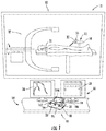
- Catheter procedure system 10 includes lab unit 11 and workstation 14.
- Catheter procedure system 10 includes a robotic catheter system, such as bedside system 12, located within lab unit 11 adjacent patient 21.
- bedside system 12 may be equipped with the appropriate percutaneous devices (e.g., guide wires, guide catheters, working catheters, catheter balloons, stents, diagnostic catheters, etc.) or other components (e.g., contrast media, medicine, etc.) to allow the user to perform a catheter based medical procedure.
- a robotic catheter system, such as bedside system 12 may be any system configured to allow a user to perform a catheter based medical procedure via a robotic system by operating various controls such as the controls located at workstation 14.
- Bedside system 12 may include any number and/or combination of components to provide bedside system 12 with the functionality described herein.
- Bedside system 12 may include a cassette 56 coupled to a base 19, and cassette 56 may include a housing 22 that supports the various components of the cassette.
- cassette 56 may include a housing 22 that supports the various components of the cassette.
- Various embodiments of bedside system 12 and cassette 56 are described in detail in P.C.T. International Application No. PCT/US2009/042720, filed May 4, 2009 .
- bedside system 12 may be equipped to perform a catheter based diagnostic procedure.
- bedside system 12 may be equipped with one or more of a variety of catheters for the delivery of contrast media to the coronary arteries.
- bedside system 12 may be equipped with a first catheter shaped to deliver contrast media to the coronary arteries on the left side of the heart, a second catheter shaped to deliver contrast media to the coronary arteries on the right side of the heart, and a third catheter shaped to deliver contrast media into the chambers of the heart.
- bedside system 12 may be equipped to perform a catheter based therapeutic procedure.
- catheter procedure system 10 may be equipped with a guide catheter, a guide wire, and a working catheter (e.g., a balloon catheter, a stent delivery catheter, an ablation catheter, etc.).
- a working catheter e.g., a balloon catheter, a stent delivery catheter, an ablation catheter, etc.
- an expandable percutaneous device e.g., an angioplasty balloon, stent, etc.
- the working catheter is navigated through a patient's vascular system to position the expandable percutaneous device at a portion of a blood vessel that has been narrowed due to a lesion caused by a disease, such as atherosclerosis.
- the expandable percutaneous device is expanded at the narrowed portion to increase the diameter of the blood vessel lumen at the lesion. This expansion allows for increased blood flow through that portion of the blood vessel.
- the expandable device is an angioplasty balloon that is expanded by being inflated to compress the material of the lesion which increases the diameter of the blood vessel.
- a stent is expanded and left inside the blood vessel at the site of a lesion to increase the diameter of the blood vessel.
- a balloon e.g., a balloon configured to deploy a stent
- the expansion of the balloon expands the stent.
- Bedside system 12 may be equipped with a variety of catheter types as needed for a particular procedure or based on the preference of the doctor performing the procedure.
- bedside system 12 may be equipped with a working catheter that includes a secondary lumen that is threaded over the guide wire during a procedure.
- bedside system 12 may be equipped with an over-the-wire working catheter that includes a central lumen that is threaded over the guide wire during a procedure.
- bedside system 12 may be equipped with an intravascular ultrasound (IVUS) catheter.
- IVUS intravascular ultrasound
- any of the percutaneous devices of bedside system 12 may be equipped with positional sensors that indicate the position of the component within the body.
- Bedside system 12 is in communication with workstation 14, allowing signals generated by the user inputs and control system of workstation 14 to be transmitted to the various devices/systems located within lab unit 11 (e.g., bedside system 12, imaging system 32, contrast injection system 13, etc.) to control the operation of the various devices/systems.
- Bedside system 12 and/or imaging system 32 also may provide feedback signals (e.g., operating conditions, warning signals, error codes, etc.) to workstation 14.
- Bedside system 12 may be connected to workstation 14 via a communication link 38 that may be a wireless connection, cable connectors, or any other means capable of allowing communication to occur between workstation 14 and beside system 12.
- Workstation 14 includes a user interface 30 configured to receive user inputs to operate various components or systems of catheter procedure system 10.
- User interface 30 includes controls 16.
- Controls 16 allow the user to control bedside system 12 to perform a catheter based medical procedure.
- controls 16 may be configured to cause bedside system 12 to perform various tasks using the various percutaneous devices with which bedside system 12 may be equipped (e.g., to advance, retract, or rotate a guide wire, advance, retract, or rotate a working catheter, advance, retract, or rotate a guide catheter, inflate or deflate a balloon located on a catheter, position and/or deploy a stent, inject contrast media into a catheter, inject medicine into a catheter, or to perform any other function that may be performed as part of a catheter based medical procedure, etc.).
- one or more of the percutaneous intervention devices may be steerable, and controls 16 may be configured to allow a user to steer one or more steerable percutaneous device.
- bedside system 12 may be equipped with a steerable guide catheter, and controls 16 may also be configured to allow the user located at remote workstation 14 to control the bending of the distal tip of a steerable guide catheter.
- controls 16 may be configured to allow a user located at workstation 14 to control operation of imaging system 32.
- controls 16 include a touch screen 18, a dedicated guide catheter control 29, a dedicated guide wire control 23, and a dedicated working catheter control 25.
- guide wire control 23 is a joystick configured to advance, retract, or rotate a guide wire
- working catheter control 25 is a joystick configured to advance, retract, or rotate a working catheter
- guide catheter control 29 is a joystick configured to advance, retract, or rotate a guide catheter.
- touch screen 18 may display one or more icons (such as icons 162, 164, and 166) that control movement of one or more percutaneous devices via bedside system 12.
- Controls 16 may also include a balloon or stent control that is configured to inflate or deflate a balloon and/or a stent.
- Each of the controls may include one or more buttons, joysticks, touch screens, etc., that may be desirable to control the particular component to which the control is dedicated.
- Controls 16 may include an emergency stop button 31 and a multiplier button 33.
- emergency stop button 31 When emergency stop button 31 is pushed a relay is triggered to cut the power supply to bedside system 12.
- Multiplier button 33 acts to increase or decrease the speed at which the associated component is moved in response to a manipulation of guide catheter control 29, guide wire control 23, and working catheter control 25. For example, if operation of guide wire control 23 advances the guide wire at a rate of 1 mm/sec, pushing multiplier button 33 may cause the operation of guide wire control 23 to advance the guide wire at a rate of 2 mm/sec.
- Multiplier button 33 may be a toggle allowing the multiplier effect to be toggled on and off. In another embodiment, multiplier button 33 must be held down by the user to increase the speed of a component during operation of controls 16.
- User interface 30 may include a first monitor 26 and a second monitor 28.
- First monitor 26 and second monitor 28 may be configured to display information or patient-specific data to the user located at workstation 14.
- first monitor 26 and second monitor 28 may be configured to display image data (e.g., x-ray images, MRI images, CT images, ultrasound images, etc.), hemodynamic data (e.g., blood pressure, heart rate, etc.), patient record information (e.g., medical history, age, weight, etc.).
- monitors 26 and/or 28 may be configured to display an image of a portion of the patient (e.g., the patient's heart) at one or more magnification levels.
- first monitor 26 and second monitor 28 may be configured to display procedure specific information (e.g., duration of procedure, catheter or guide wire position, volume of medicine or contrast agent delivered, etc.). Monitor 26 and monitor 28 may be configured to display information regarding the position and/or bend of the distal tip of a steerable guide catheter. Further, monitor 26 and monitor 28 may be configured to display information to provide the functionalities associated with the various modules of controller 40 discussed below.
- user interface 30 includes a single screen of sufficient size to display one or more of the display components and/or touch screen components discussed herein.
- Catheter procedure system 10 also includes an imaging system 32 located within lab unit 11.
- Imaging system 32 may be any medical imaging system that may be used in conjunction with a catheter based medical procedure (e.g., angiogram system, non-digital x-ray, digital x-ray, CT, MRI, ultrasound, etc.).
- imaging system 32 is a digital x-ray imaging device that is in communication with workstation 14.
- imaging system 32 may include a C-arm that allows imaging system 32 to partially or completely rotate around patient 21 in order to obtain images at different angular positions relative to patient 21 (e.g., sagital views, caudal views, cranio-caudal views, etc.).
- Imaging system 32 is configured to take x-ray images of the appropriate area of patient 21 during a particular procedure.
- imaging system 32 may be configured to take one or more x-ray images of the heart to diagnose a heart condition.
- Imaging system 32 may also be configured to take one or more x-ray images during a catheter based medical procedure (e.g., real-time images) to assist the user of workstation 14 to properly position a guide wire, guide catheter, working catheter, stent, etc. during the procedure.
- the image or images may be displayed on first monitor 26 and/or second monitor 28.
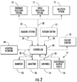
- Catheter procedure system 10 may include a control system, such as controller 40.
- Controller 40 may be part of workstation 14.
- Controller 40 is in communication with one or more bedside systems 12, controls 16, monitors 26 and 28, imaging system 32, and patient sensors 35 (e.g., electrocardiogram ("ECG”) devices, electroencephalogram (“EEG”) devices, blood pressure monitors, temperature monitors, heart rate monitors, respiratory monitors, etc.).
- ECG electrocardiogram
- EEG electroencephalogram
- controller 40 may be in communication with a hospital data management system or hospital network 34, one or more additional output devices 36 (e.g., printer, disk drive, cd/dvd writer, etc.), and a hospital inventory management system 37.
- Controller 40 may also be in communication with a contrast injection system 13, a drug injection system 15 and an ablation system 17.
- Communication between the various components of catheter procedure system 10 may be accomplished via communication links 38.
- Communication links 38 may be dedicated wires or wireless connections.
- Communication links 38 may also represent communication over a network.
- Catheter procedure system 10 may be connected or configured to include any other systems and/or devices not explicitly shown.
- catheter procedure system 10 may include IVUS systems, image processing engines, data storage and archive systems, automatic balloon and/or stent inflation systems, medicine tracking and/or logging systems, user logs, encryption systems, systems to restrict access or use of catheter procedure system 10, robotic catheter systems of the past, present, or future, etc.
- catheter procedure system 10 may include various actuating mechanisms that engage and impart motion to an associated percutaneous device in response to a user's manipulation of controls 16 and/or under control of controller 40.
- catheter procedure system 10 includes a guide wire actuating mechanism 50, a working catheter actuating mechanism 52, and a guide catheter actuating mechanism 54.
- catheter procedure system 10 may include an actuating mechanism for inflating an angioplasty or stent delivery balloon.
- guide wire actuating mechanism 50 and working catheter actuating mechanism 52 are incorporated within cassette 56. Additional embodiments of bedside system 12 and cassette 56 are described in detail in P.C.T. International Application No. PCT/US2009/042720, filed May 4, 2009 .
- Guide wire actuating mechanism 50 is coupled to guide wire 58 such that guide wire actuating mechanism 50 is able to cause guide wire 58 to advance, retract, and rotate.
- Working catheter actuating mechanism 52 is coupled to working catheter 60 such that working catheter actuating mechanism 52 is able to cause working catheter 60 to advance, retract, and rotate.
- Connector 62 couples guide catheter 64 to guide catheter actuating mechanism 54 such that guide catheter actuating mechanism 54 is able to cause guide catheter 64 to advance, retract, and rotate.
- guide wire actuating mechanism 50, working catheter actuating mechanism 52, and guide catheter actuating mechanism 54 may each include an engagement structure suitable for engaging the respective percutaneous device such that the actuating mechanism is able to impart axial and/or rotational movement to the percutaneous device.
- a Y-connector 66 is coupled to guide catheter actuating mechanism 54 via connector 68.
- connector 68 may be a component separate from both Y-connector 66 and guide catheter actuating mechanism 54.
- connector 68 may be part of (e.g., integral with) Y-connector 66 or part of actuating mechanism 54.
- Y-connector 66 is also connected to cassette 56.
- Y-connector 66 includes a first leg, a second leg, and a third leg.
- the first leg of the Y-connector is connected to or in communication with the internal lumen of guide catheter 64.
- the second leg is angled away from the longitudinal axis of guide catheter 64.
- the second leg provides a port for the injection of fluids (e.g., contrast media, medicine, etc.) into the lumen of guide catheter 64.
- contrast injection system 13 is coupled to the second leg of Y-connector 66 via a conduit 65 that allows contrast media to be delivered from contrast injection system 13 to Y-connector 66.
- the third leg of Y-connector 66 is coupled to a cassette 56 and receives both guide wire 58 and working catheter 60.
- guide wire 58 and working catheter 60 are inserted through Y-connector 66 into the internal lumen of guide catheter 64.
- Guide wire actuating mechanism 50 includes a rotate actuator 70 and an advance/retract actuator 72.
- Rotate actuator 70 is configured to cause rotation of guide wire 58 about its longitudinal axis.
- Advance/retract actuator 72 is configured to advance and/or retract guide wire 58 (i.e., to advance and/or retract along the longitudinal axis of the guide wire) within patient 21.
- Working catheter actuating mechanism 52 includes a rotate actuator 74 and an advance/retract actuator 76.
- Rotate actuator 74 is configured to cause rotation of working catheter 60 about its longitudinal axis.
- Advance/retract actuator 76 is configured to advance and/or retract working catheter 60 (i.e., to advance and/or retract along the longitudinal axis of the working catheter) within patient 21.
- Guide catheter actuating mechanism 54 includes a rotate actuator 78, an advance/retract actuator 80, and a bend actuator 82.
- Rotate actuator 78 is configured to cause rotation of guide catheter 64 about its longitudinal axis.
- Advance/retract actuator 80 is configured to advance and/or retract guide catheter 64 (i.e., to advance and/or retract along the longitudinal axis of the guide catheter) within patient 21.
- guide catheter 64 may include one or more bend control elements that allow the user to cause bending of the distal tip of guide catheter 64.
- bend actuator 82 causes the distal tip of guide catheter 64 to bend in response to the user's manipulation of controls 16.
- controls 16 and controller 40 located at workstation 14 are communicably coupled to various portions of bedside system 12 to allow the user to control movement of guide wire 58, working catheter 60 and guide catheter 64 and any other percutaneous devices that bedside system 12 is equipped with.
- Controls 16 and controller 40 are communicably coupled to guide catheter actuating mechanism 54 to allow the user to move guide catheter 64.
- controls 16 are communicably coupled to cassette 56 to allow the user to control guide wire 58 via guide wire actuating mechanism 50 and to control working catheter 60 via working catheter actuating mechanism 52.
- controller 40 may be configured to provide automated movement of a percutaneous device.
- cassette 56 is configured to be coupled to a motor drive base 19 (shown in FIG. 1 ).
- each of the actuators 70, 72, 74, and 76 of cassette 56 are configured to engage capstans extending from the motor drive base.
- Motors located within the motor drive base drive (e.g., rotate) the capstans, which in turn drive the actuators 70, 72, 74, and 76 of cassette 56.
- the actuators 70, 72, 74, and 76 of cassette 56 transfer the rotational movement of the capstans to cause the movement of guide wire 58 and working catheter 60.
- the motors that drive the capstans of the motor drive base may be located outside of the base connected to cassette 56 via an appropriate transmission device (e.g., shaft, cable, etc.).
- cassette 56 includes motors located within cassette 56 associated with the actuators 70, 72, 74, and 76, and cassette 56 is mounted to a base providing a power supply (e.g., battery, AC building power supply, etc.) to the motors within cassette 56.
- Catheter procedure system 10 is also configured to provide control of imaging system 32 and contrast injection system 13 via controls 16 and/or controller 40.
- controls 16 and controller 40 are located at workstation 14 and are communicably coupled to imaging system 32 and to contrast injection system 13 to allow the user to control imaging system 32 and contrast injection system 13 from workstation 14.
- catheter procedure system 10 is configured such that control of imaging system 32 and/or contrast injection system 13 is integrated with control of bedside system 12 to provide for convenient, efficient and intuitive control over both systems by a user located at workstation 14.
- various functions of imaging system 32 e.g., image capture, magnification, collimation, c-arm positioning, etc. may be controlled via controls 16 and/or controller 40.
- controls 16 may be configured to allow the user positioned at workstation 14 to directly control operation of imaging system 32 via interaction with controls 16 that specifically operate imaging system 32 (e.g., via interaction with an imaging start button, an image system "on-off" button, an image system touch screen icon, a user entered text command to start imaging, selection of an imaging activation element from a drop down menu, etc.).
- catheter procedure system 10 may be configured to provide for automatic, intelligent or semi-automatic control of imaging system 32 via controller 40 (e.g., without requiring the user to interact with a control specific to the imaging system).
- the user of workstation 14 may be able to control the angular position of imaging system 32 relative to the patient to obtain and display various views of the patient's heart on first monitor 26 and/or second monitor 28 via operation of controls 16.
- controller 40 may automatically control the angular position of imaging system 32 according to a particular module or set of instructions. Displaying different views at different portions of the procedure may aid the user of workstation 14 to properly move and position the percutaneous devices within the 3D geometry of the patient's heart. For example, displaying the proper view during a procedure may allow the user to view a patient's vascular system from the proper angle to ensure that the distal tip of a steerable guide catheter is bent in the proper way to ensure the catheter is moved as intended.
- imaging system 32 may be any 3D imaging modality of the past, present, or future, such as an x-ray based computed tomography (CT) imaging device, a magnetic resonance imaging device, a 3D ultrasound imaging device, etc.
- CT computed tomography
- the image of the patient's heart that is displayed during a procedure may be a 3D image.
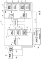
- Controller 40 generally may be an electronic control unit suitable to provide catheter procedure system 10 with the various functionalities described herein.
- controller 40 may be an embedded system, a dedicated circuit, a general purpose system programmed with the functionality described herein, etc.
- Controller 40 includes a processing circuit 90, memory 92, communication module or subsystem 94, communication interface 96, procedure control module or subsystem 98, simulation module or subsystem 100, assist control module or subsystem 102, mode selection module or subsystem 104, inventory module or subsystem 106, GUI module or subsystem 108, data storage module or subsystem 110, and record module or subsystem 112.
- controller 40 may include a movement instruction module that includes one or more instruction sets that dictate how bedside system 12 responds to a user's manipulation of controls 16 to cause a percutaneous device to move in a particular way.
- the movement instruction module may include various instruction sets to facilitate traversal of a vascular occlusion by the percutaneous devices as discussed herein.
- Various embodiments of a catheter procedure system 10 including a movement instruction module are disclosed in P.C.T. International Application No. PCT/US2010/52178, filed October 11, 2010 .
- Processing circuit 90 may be a general purpose processor, an application specific processor (ASIC), a circuit containing one or more processing components, a group of distributed processing components, a group of distributed computers configured for processing, etc., configured provide the functionality of module or subsystem components 94, 98-112.
- Memory 92 e.g., memory unit, memory device, storage device, etc.
- Memory 92 may be one or more devices for storing data and/or computer code for completing and/or facilitating the various processes described in the present disclosure.
- Memory 92 may include volatile memory and/or non-volatile memory.
- Memory 92 may include database components, object code components, script components, and/or any other type of information structure for supporting the various activities described in the present disclosure.
- any distributed and/or local memory device of the past, present, or future may be utilized with the systems and methods of this disclosure.
- memory 92 is communicably connected to processing circuit 90 and module components 94, 98-112 (e.g., via a circuit or any other wired, wireless, or network connection) and includes computer code for executing one or more processes described herein.
- a single memory unit may include a variety of individual memory devices, chips, disks, and/or other storage structures or systems.
- Module or subsystem components 94, 98-112 may be computer code (e.g., object code, program code, compiled code, script code, executable code, non-transitory programmed instructions, or any combination thereof), hardware, software, or any combination thereof, for conducting each module's respective functions.
- Module components 94, 98-112 may be stored in memory 92, or in one or more local, distributed, and/or remote memory units configured to be in communication with processing circuit 90 or another suitable processing system.
- Communication interface 96 includes one or more component for communicably coupling controller 40 to the other components of catheter procedure system 10 via communication links 38.
- Communication interface 96 may include one or more jacks or other hardware for physically coupling communication links 38 to controller 40, an analog to digital converter, a digital to analog converter, signal processing circuitry, and/or other suitable components.
- Communication interface 96 may include hardware configured to connect controller 40 with the other components of catheter procedure system 10 via wireless connections.
- Communication module 94 is configured to support the communication activities of controller 40 (e.g., negotiating connections, communication via standard or proprietary protocols, etc.).
- Data storage module 110 is configured to support the storage and retrieval of information by controller 40.
- data storage module 110 is a database for storing patient specific data, including image data.
- data storage module 110 may be located on hospital network 34.
- Data storage module 110 and/or communication module 94 may also be configured to import and/or export patient specific data from hospital network 34 for use by controller 40.
- Controller 40 includes a GUI module 108 the controls the display of various information on the display devices (e.g., monitors 26 and 28, touch screen 18, etc.) of workstation 14.
- GUI module 108 is configured to display image data captured by imaging system 32 during a procedure to assist the user of catheter procedure system 10 perform a procedure.
- Controller 40 also includes a procedure control module 98 configured to support the control of various devices/systems located within lab unit 11 (e.g., bedside system 12, imaging system 32, contrast injection system 13, etc.) by a user located at workstation 14 during a catheter based medical procedure.
- procedure control module 98 allows the user to operate bedside system 12, imaging system 32, and/or contrast injection system 13 by manipulating controls 16.
- procedure control module 98 is configured to generate one or more control signals 116 based upon the user's manipulation of controls 16 and/or based upon other data, modules, instruction sets, etc. available to procedure control module 98.
- Control signals 116 may also be generated by controller 40 to provide for automatic (e.g., control signals not based on user operation of controls 16) or semi-automatic (e.g., control signals partially based on user operation of controls 16) control of bedside system 12, imaging system 32, contrast injection system 13, etc.
- automatic e.g., control signals not based on user operation of controls 16
- semi-automatic e.g., control signals partially based on user operation of controls 16
- control signals 116 generated by procedure control module 98 are communicated from controller 40 to the various actuators of bedside system 12, to imaging system 32, to contrast injection system 13, and to any other device or system controlled by controller 40.
- the actuators of cassette 56 cause movement of the guide wire, working catheter and/or guide catheter.
- the actuators of bedside system 12 cause movement of the percutaneous devices in response to user inputs received by controls 16 and based on other data or control schemes discussed herein.
- imaging system 32 e.g., image capture, magnification, collimation, c-arm positioning, etc.
- various functions of imaging system 32 are controlled in response to control signals 116, and injection of contrast media into the patient by contrast injection system 13 is controlled in response to control signals 116.
- Procedure control module 98 may also cause data appropriate for a particular procedure to be displayed on monitors 26 and 28.
- Procedure control module 98 may also cause various icons (e.g., icons 162, 164, 166, etc.) to be displayed on touch screen 18 that the user may interact with to control the use of bedside system 12.
- controls 23, 25 and 29 are joystick controls that, when actuated by the user, cause procedure control module 98 to generate one or more control signals 116 which in turn cause bedside system 12 to move (e.g., advance, retract, rotate, etc.) the guide wire, working catheter and guide catheter, respectively.
- the movement rate of a percutaneous device caused by bedside system 12 is a function of or is proportional to the degree of displacement of the joystick from the resting position and the direction of movement is a function of the direction of joystick displacement.
- catheter procedure system 10 may be configured such that control of imaging system 32 and contrast injection system 13 are integrated with control of bedside system 12 to provide for convenient, efficient and intuitive control over both systems by a user located at workstation 14.
- catheter procedure system 10 may be configured to automatically activate image capture by imaging system 32 immediately prior to percutaneous device movement, to maintain image capture during percutaneous device movement and to automatically cease image capture following percutaneous device movement.
- FIG. 6 is a flow-diagram depicting a process of automatic image capture integrated with control of a robotic catheter system according to an exemplary embodiment.
- the process shown in FIG. 6 may be performed by a controller 40 including a module (e.g., procedure control module 98) that is configured to provide this functionality.
- a module e.g., procedure control module 98
- controller 40 of catheter procedure system 10 receives an input indicative of upcoming percutaneous device movement.
- the input received at step 170 may indicate that the user located at workstation 14 intends to move a percutaneous device with bedside system 12 by interacting with controls 16.
- procedure control module 98 automatically generate a control signal 116 based upon the input received at step 170.
- the control signal generated at step 172 are communicated to imaging system 32, and imaging system 32 is responsive to these control signals to trigger capture of images.
- the images captured in response to these control signals are captured prior to movement of the percutaneous device.
- the captured images are displayed to the user located at workstation 14 via a display, such as monitors 26 and 28.
- procedure control module 98 generates one or more control signals 116 that are communicated to one or more actuator of bedside system 12 (in addition to the control signals causing image capture) to cause movement of the percutaneous device in accordance with the user's manipulation of controls 16.
- procedure control module 98 determines whether the user is still operating controls 16 to cause movement of the percutaneous device. If the user is still operating controls 16, then at step 180 procedure control module 98 continues to generate control signals to capture images via imaging system 32, to display images on monitors 26 and 28 and to cause movement of the percutaneous device via bedside system 12. In this manner, images captured by image system 32 are displayed immediately prior to percutaneous device movement and continuously during percutaneous device movement.
- procedure control module 98 is configured to control both image capture and percutaneous device movement in an intuitive manner via user interaction with a single control associated with the percutaneous device. This eliminates the need for the user to independently and separately actuate a separate control (e.g., a dedicated imaging system activation button) to trigger image capture prior to percutaneous device movement.
- a separate control e.g., a dedicated imaging system activation button
- procedure control module 98 is configured to continuously cause the display of the last image captured by imaging system 32 on monitors 26 or 28 after device movement has stopped.
- the user located at workstation 14 can easily view the last captured image as the user decides the next action to take during the procedure.
- FIGS. 7A-7C show a catheter procedure system 10 configured to receive an input indicative of upcoming percutaneous device movement.
- Controller 40 e.g., via instructions of procedure control module 98
- image capture via imaging system 32 is triggered when the user first begins to interact with one of the input devices or controls of controls 16 but prior to triggering movement of the percutaneous device in response to the user's interaction with the input device.
- a control for example working catheter joystick 25, is shown in the resting position (e.g., the non-actuated position, prior to movement of the control by the user).
- Working catheter control 25 may include an activation zone 184 surrounding control 25 such that control 25 is located within activation zone 184 when the control is in the resting position. With the control in the resting position, controller 40 does not generate control signals to either imaging system 32 or bedside system 12.
- control 25 is shown displaced from the resting position but still within activation zone 184, and in this embodiment, this position of control 25 generates the input indicative of upcoming percutaneous device movement that is received at step 170 in FIG. 6 .
- procedure control module 98 is configured to generates one or more control signals 116 to instruct imaging system 32 to begin image capture but does not generate control signals 116 to the actuators of bedside system 12.
- activation zone 184 is the zone in which control 25 may be actuated from the resting position such that image capture is triggered but device movement is not yet started.
- procedure control module 98 is configured to generate a control signal 116 that is communicated to an actuator of bedside system 12 to cause movement of the percutaneous device in accordance with the movement of the control 25.
- procedure control module 98 is configured to continue to generate the control signals that cause capture of images at the same time as it is generating the control signals that cause movement of the percutaneous device. In this manner, image capture and display continues to occur as the percutaneous device is being moved by the user.
- procedure control module 98 is configured to stop generation of both the control signals to imaging system 32 and to bedside system 12 when control 25 is returned to the resting position of FIG. 7A .
- activation zone 184 is a graphical representation of the amount of displacement of control 25 that is necessary to generate control signals to imaging system 32 and to bedside system 12 (i.e., the size of activation zone 184).
- the size of activation zone 184 may be determined by the configuration of procedure control module 98.
- procedure control module 98 may include computer code or instructions that dictate how much displacement of the control is necessary to generate the different control signals.
- procedure control module 98 will be configured such that size of activation zone 184 is fairly small (e.g., less than 1 mm, less than 5 mm, less than 10 mm, etc.) to ensure that control 25 does not need to be moved a large distance in order to trigger movement of the percutaneous device.
- FIGS. 7A-7C utilizes the amount of displacement of a percutaneous device control as the input that indicates upcoming percutaneous device movement and that automatically triggers image capture prior to percutaneous device movement.
- procedure control module 98 may be configured such that once working catheter control 25 is actuated by the user, image capture by imaging system 32 is triggered and movement of the percutaneous device in response to the user operation of control 25 is delayed until image acquisition and display has started.
- the input indicative of upcoming percutaneous device movement is the input received by controller 40 that is generated by actuation of control 25.
- the input that triggers image capture is initial interaction with control 25 by the user, and controller 40 generates the control signal to bedside system 12 to cause movement of the percutaneous device after a predetermined time following generation of the control signal to the imaging system.
- controller 40 may receive feedback signals from imaging system 32 or from the display components indicating that image acquisition and display has started. Once image acquisition has started and the image is displayed, procedure control module 98 then generates control signals to bedside system 12 to cause movement of the percutaneous device in accordance with the user's manipulation of the control. In one such embodiment, controller 40 may be configured to generate the control signal to bedside system 12 to cause movement of the percutaneous device only after the imaging system has begun image capture.
- the input indicative of the user's intent to move a percutaneous device may be generated by devices other than one of the percutaneous device controls of workstation 14.
- workstation 14 may include one or more sensors 186 (shown in FIG. 5 ) configured to detect the presence of a user's hand approaching one of the percutaneous device controls (e.g., controls 23, 25, 29) of controls 16.
- the sensors may be a one or more of a variety of different proximity sensors (e.g., infrared sensors, optical sensors, capacitive sensors, reflective sensors, etc.) mounted to the housing of controls 16 and adjacent to the individual input device of controls 16 that the sensor is associated with.
- activation zone 184 is established by the proximity sensor, and upcoming percutaneous device movement is indicated by the proximity sensor when the user's hand is detected within the activation zone.
- the proximity sensor transmits a "presence" signal to controller 40 when the proximity sensor detects the presence of a user's hand adjacent the control, and, based upon this input from the proximity sensor, controller 40 generates one or more control signal 116 to trigger image capture by imaging system 32.
- procedure control module 98 may be configured to stop image capture and percutaneous device movement when the control is returned to the resting position. In another embodiment, procedure control module 98 may be configured to stop percutaneous device movement when the control is returned to the resting position and to stop image acquisition when the proximity sensor indicates that the user's hand has exited activation zone 184.
- controller 40 may include a prediction module that is configured (e.g., programmed) with an algorithm that predicts when the next movement of a percutaneous device is likely to be initiated based on identified patterns of use of the various controls.
- the prediction module provides the input indicative of upcoming device movement to procedure control module 98, and procedure control module 98 then triggers image capture prior to the predicted time of movement initiation. For example, if the control use pattern indicates that working catheter control 25 is typically actuated after a certain time period (e.g., 10 seconds) following operation of guide wire control 23, procedure control module 98 may be configured to trigger image capture via imaging system 32 immediately before the time period expires following operation of guide wire control 23.
- the input indicative of upcoming percutaneous device movement is not an input generated by a dedicated or specific imaging system control (e.g., via interaction with an imaging start button, an image system on button, an image system touch screen icon, a user entered text command to start imaging, selection of an imaging activation element from a drop down menu, etc.).
- controls 16 may include a dedicated or specific imaging system control to allow the user to directly control imaging system 32 independent from the automatic or semi-automatic control that is based on the input indicative of upcoming device movement.
- any control e.g., guide wire control 23, guide catheter control 29, touch screen icons 162, 164, 166, etc. located at workstation 14 may include various activation zones as discussed above.
- controller 40 may be in communication with contrast injection system 13.
- a catheter procedure system including a contrast media injection system are described in detail in P.C.T. International Application No. PCT/US2009/067540, filed December 10, 2009 .
- catheter procedure system 10 may be configured to automatically trigger injection of contrast media via contrast injection system 13 prior to percutaneous device movement and prior to automatic image capture to ensure sufficient contrast media is present within a patient's vasculature during image capture.
- controller 40 is configured to generate one or more control signal 116 to contrast injection system 13 based upon an input indicative of upcoming percutaneous device movement.
- FIG. 8 is a flow-diagram depicting a process of automatic contrast media injection and automatic image capture integrated with control of a robotic catheter system according to an exemplary embodiment.
- the process shown in FIG. 8 may be performed by a controller 40 including a module (e.g., procedure control module 98) that is configured to provide this functionality.
- a module e.g., procedure control module 98
- catheter procedure system 10 receives an input indicating that the user located at workstation 14 intends to move a percutaneous device with bedside system 12 by interacting with controls 16. Any of the inputs indicating upcoming device movement discussed above may be received at step 190.
- procedure control module 98 automatically generates control signals 116 based upon the input received at step 190, and the generated control signals 116 are communicated to contrast injection system 13 to trigger injection of contrast media prior to both image capture and movement of the percutaneous device.
- procedure control module 98 automatically generates control signals 116 based upon the input received at step 190, and the generated control signals 116 are communicated to imaging system 32 to trigger image capture by imaging system 32 prior to movement of the percutaneous device but after injection of contrast media at step 192.
- the captured images are displayed to the user located at workstation 14 via a display, such as monitors 26 and 28.
- procedure control module 98 generates one or more control signals 116 that are communicated to one or more actuator of bedside system 12 (in addition to the control signals causing image capture and contrast injection) to cause movement of the percutaneous device in accordance with the user's manipulation of controls 16.
- procedure control module 98 determines whether the user is still operating controls 16 to cause movement of the percutaneous device. If the user is still operating controls 16, then at step 202 procedure control module 98 continues to generate control signals to periodically inject contrast media via contrast injection system 13, to capture images via imaging system 32, to display the captured images and to cause movement of the percutaneous device via bedside system 12. In this manner, images captured by image system 32 are displayed immediately prior to percutaneous device movement and continuously during percutaneous device movement.
- procedure control module 98 is configured to control contrast injection, image capture and percutaneous device movement in an intuitive manner via interaction by the user with a single control associated with the percutaneous device. This eliminates the need for the user to independently and separately actuate a separate control to trigger contrast media injection or image capture prior to percutaneous device movement.
Landscapes
- Health & Medical Sciences (AREA)
- Life Sciences & Earth Sciences (AREA)
- Engineering & Computer Science (AREA)
- Medical Informatics (AREA)
- Surgery (AREA)
- Nuclear Medicine, Radiotherapy & Molecular Imaging (AREA)
- General Health & Medical Sciences (AREA)
- Public Health (AREA)
- Animal Behavior & Ethology (AREA)
- Veterinary Medicine (AREA)
- Heart & Thoracic Surgery (AREA)
- Biomedical Technology (AREA)
- Molecular Biology (AREA)
- Pathology (AREA)
- Radiology & Medical Imaging (AREA)
- Biophysics (AREA)
- Physics & Mathematics (AREA)
- High Energy & Nuclear Physics (AREA)
- Optics & Photonics (AREA)
- Robotics (AREA)
- Human Computer Interaction (AREA)
- Gynecology & Obstetrics (AREA)
- Oral & Maxillofacial Surgery (AREA)
- Apparatus For Radiation Diagnosis (AREA)
- Anesthesiology (AREA)
- Hematology (AREA)
- Pulmonology (AREA)
- Vascular Medicine (AREA)
Claims (10)
- Ein Roboterkatheter-Verfahrenssystem (10), das so gestaltet ist, dass es in Verbindung mit einem medizinischen Bildgebungssystem (32) betrieben werden kann, das Folgendes aufweist:ein Krankenbettsystem (12), das einen Betätigungsmechanismus (50, 52, 54) aufweist, der so gestaltet ist, dass er eine Bewegung auslösen und auf ein perkutanes Gerät (58, 60, 64) übertragen kann; undeinen Arbeitsplatzrechner (14), der Arbeitsplatzrechner weist dabei Folgendes auf: eine Benutzeroberfläche (30);ein Steuerungssystem (40), das so gestaltet ist, dass es funktionsfähig mit der Benutzeroberfläche (30), dem Krankenbettsystem (12) und dem medizinischen Bildgebungssystem (32) gekoppelt werden kann, das Steuerungssystem reagiert dabei auf eine erste Eingabe und auf eine zweite Eingabe, wobei die Benutzeroberfläche eine zweite Eingabe von einem Benutzer empfängt, das Steuerungssystem ist dabei so gestaltet, dass es Folgendes erzeugt:gekennzeichnet dadurch, dassein erstes Steuerungssignal (116) an ein medizinisches Bildgebungssystem (32), auf Grundlage der ersten Eingabe, wobei das medizinische Bildgebungssystem mindestens ein Bild als Reaktion auf das erste Steuerungssignal aufnimmt; undein zweites Steuerungssignal (116) an den Betätigungsmechanismus (50, 52, 54), auf der Grundlage der zweiten Eingabe, wobei der Betätigungsmechanismus eine Bewegung des perkutanen Geräts in Reaktion auf das zweite Steuerungssignal auslöst;die Benutzeroberfläche (30) eine Steuerung (16) einschließt, wobei die erste Eingabe eine anfängliche Interaktion mit der Steuerung durch einen Benutzer ist, und darüberhinaus dadurch gekennzeichnet, dass das Steuerungssystem so gestaltet ist, dass es das zweite Steuerungssignal (116) nach einer vorbestimmten Zeit nach der Erzeugung des ersten Steuerungssignals (116) erzeugt.
- Das Roboterkatheter-Verfahrenssystems gemäß Anspruch 1, wobei die Steuerung (16) so gestaltet ist, dass sie sowohl die erste als auch die zweite Eingabe empfangen kann.
- Das Roboterkatheter-Verfahrenssystems gemäß Anspruch 2, wobei die Steuerung (16) ein Joystick (23, 25, 29) ist.
- Das Roboterkatheter-Verfahrenssystems gemäß Anspruch 3, wobei die erste Eingabe eine erste Verschiebung des Joysticks (23, 25, 29) und die zweite Eingabe eine zweite Verschiebung des Joysticks (23, 25, 29) ist.
- Das Roboterkatheter-Verfahrenssystems gemäß Anspruch 4, wobei die erste Verschiebung geringer ist als die zweite Verschiebung.
- Das Roboterkatheter-Verfahrenssystems gemäß Anspruch 1 oder eines vorhergehenden Anspruchs, wobei:(i) das perkutane Gerät ausgewählt ist aus der Gruppe bestehend aus einem Führungsdraht (58), einem Arbeitskatheter (60) und einem Führungskatheter (64); und/oder(ii) das Steuerungssystem (40) so gestaltet ist, dass es das erste Steuerungssignal (116) vor dem zweiten Steuerungssignal (116) erzeugen kann, so dass das medizinische Bildgebungssystem (32) beginnt, Bilder vor der Bewegung des perkutanen Geräts aufzunehmen.
- Das Roboterkatheter-Verfahrenssystem gemäß Anspruch 1 oder eines der vorhergehenden Ansprüche, wobei der Arbeitsplatzrechner (14) einen Sensor (186) einschließt, der so gestaltet ist, dass er das Vorhandensein der Benutzerhand an der Benutzeroberfläche (30) erkennt, wobei die erste Eingabe vom Sensor (186) erzeugt wird, und wobei der Sensor optional ein Näherungssensor ist.
- Das Roboterkatheter-Verfahrenssystems gemäß Anspruch 1 oder eines der vorhergehenden Ansprüche, wobei:(i) die erste Eingabe einen Versuch des Benutzers anzeigt, eine Bewegung des perkutanen Geräts auszulösen; und/oder(ii) die erste Eingabe und die zweite Eingabe von einem Benutzer über eine Einzelsteuerung (16) empfangen werden und darüberhinaus wobei das Steuerungssystem (40) so gestaltet ist, dass es das zweite Signal (116) nur erzeugt, wenn das Bildgebungssystem begonnen hat, Bilder aufzunehmen.
- Das Roboterkatheter-Verfahrenssystem gemäß Anspruch 1 oder eines der vorhergehenden Ansprüche, das darüberhinaus ein Kontrastmittel-Einspritzsystem (13) aufweist, wobei das Steuerungssystem (40) ein drittes Steuerungssignal (116) an das Kontrastmittel-Einspritzsystem (13), auf der Grundlage der ersten Eingabe, erzeugt, wobei das Kontrastmittel-Einspritzsystem ein Kontrastmittel in einen Patienten (21) leitet, als Reaktion auf das dritte Steuerungssignal.
- Das Roboterkatheter-Verfahrenssystem gemäß Anspruch 9, wobei das Steuerungssystem (40) das dritte Steuerungssignal (116) vor dem ersten Steuerungssignal (116) erzeugt, so dass das Kontrastmittel zum Patienten (21) vor Beginn der Bilderfassung geleitet wird.
Applications Claiming Priority (2)
| Application Number | Priority Date | Filing Date | Title |
|---|---|---|---|
| US201161466399P | 2011-03-22 | 2011-03-22 | |
| PCT/US2012/030068 WO2012129374A1 (en) | 2011-03-22 | 2012-03-22 | Robotic catheter system including imaging system control |
Publications (3)
| Publication Number | Publication Date |
|---|---|
| EP2688632A1 EP2688632A1 (de) | 2014-01-29 |
| EP2688632A4 EP2688632A4 (de) | 2014-10-08 |
| EP2688632B1 true EP2688632B1 (de) | 2016-05-18 |
Family
ID=46879736
Family Applications (1)
| Application Number | Title | Priority Date | Filing Date |
|---|---|---|---|
| EP12761249.7A Active EP2688632B1 (de) | 2011-03-22 | 2012-03-22 | Roboterkathetersystem mit bildgebungssystemsteuerung |
Country Status (3)
| Country | Link |
|---|---|
| US (4) | US9320479B2 (de) |
| EP (1) | EP2688632B1 (de) |
| WO (1) | WO2012129374A1 (de) |
Cited By (1)
| Publication number | Priority date | Publication date | Assignee | Title |
|---|---|---|---|---|
| CN108472090A (zh) * | 2015-12-29 | 2018-08-31 | 皇家飞利浦有限公司 | 用于控制外科手术机器人的系统、控制单元和方法 |
Families Citing this family (37)
| Publication number | Priority date | Publication date | Assignee | Title |
|---|---|---|---|---|
| WO2010025338A1 (en) * | 2008-08-29 | 2010-03-04 | Corindus Ltd. | Catheter control system and graphical user interface |
| CA2896021A1 (en) * | 2012-12-21 | 2014-06-26 | Volcano Corporation | Adaptive interface for a medical imaging system |
| US9069396B2 (en) * | 2013-03-12 | 2015-06-30 | Lightlab Imaging, Inc. | Controller and user interface device, systems, and methods |
| WO2014162275A1 (en) * | 2013-04-03 | 2014-10-09 | Koninklijke Philips N.V. | Interventional x-ray system |
| JP6725424B2 (ja) | 2014-03-17 | 2020-07-15 | インテュイティブ サージカル オペレーションズ, インコーポレイテッド | 遠隔操作医療システムのための誘導セットアップ |
| KR102450087B1 (ko) | 2014-03-17 | 2022-10-06 | 인튜어티브 서지컬 오퍼레이션즈 인코포레이티드 | 원격 조종 의료 시스템에서 미리 설정된 암 위치를 가지는 자동화된 구조 |
| US11304668B2 (en) | 2015-12-15 | 2022-04-19 | Corindus, Inc. | System and method for controlling X-ray frame rate of an imaging system |
| US10245112B2 (en) | 2016-06-27 | 2019-04-02 | Corindus, Inc. | Interlocking system and method for joysticks in a catheter procedure system |
| US10568598B2 (en) * | 2016-06-29 | 2020-02-25 | Wisconsin Alumni Research Foundation | Fluoroscopy system resolving slowly evolving conditions |
| US20180021544A1 (en) * | 2016-07-25 | 2018-01-25 | General Electric Company | Catheter-Based User Interface Device For Remote Control Of Display Images |
| US11395708B2 (en) | 2018-06-20 | 2022-07-26 | Gabriel Gruionu | Systems and methods for automatic guidance of medical catheters and endoscopes |
| EP4245240A3 (de) | 2019-07-15 | 2023-11-15 | Corindus, Inc. | Systeme und verfahren für eine steuerungsstation für robotische interventionelle eingriffe unter verwendung mehrerer länglicher medizinischer vorrichtungen |
| US20210045824A1 (en) | 2019-08-15 | 2021-02-18 | Auris Health, Inc. | Axial motion drive devices, systems, and methods for a robotic medical system |
| EP4044906B1 (de) | 2019-10-15 | 2025-03-12 | Kandu Health, Inc. | Systeme und verfahren zur mehrgrössenhubdetektion |
| DE102020204985A1 (de) | 2020-04-21 | 2021-10-21 | Siemens Healthcare Gmbh | Steuerung eines robotisch bewegten medizinischen Objekts |
| EP4259030A4 (de) * | 2021-01-14 | 2025-01-01 | Corindus, Inc. | Systeme und verfahren für eine steuerungsstation für robotische interventionelle eingriffe unter verwendung mehrerer länglicher medizinischer vorrichtungen |
| CN113100690A (zh) * | 2021-03-29 | 2021-07-13 | 谈斯聪 | 一种体内微型机器人装置、最优化治疗调控系统及方法 |
| US12035989B2 (en) | 2021-08-02 | 2024-07-16 | Corindus, Inc. | Systems and methods for a control station for robotic interventional procedures using a plurality of elongated medical devices |
| US12419703B2 (en) | 2022-08-01 | 2025-09-23 | Imperative Care, Inc. | Robotic drive system for achieving supra-aortic access |
| US12564414B2 (en) | 2022-08-01 | 2026-03-03 | Imperative Care, Inc. | Method of supra-aortic access for a neurovascular procedure |
| US12564458B2 (en) | 2022-08-01 | 2026-03-03 | Imperative Care, Inc. | Method of robotically driving a multi catheter assembly above the aortic arch |
| US12446979B2 (en) | 2022-08-01 | 2025-10-21 | Imperative Care, Inc. | Method of performing a multi catheter robotic neurovascular procedure |
| US12447317B2 (en) | 2022-08-01 | 2025-10-21 | Imperative Care, Inc. | Method of priming concentrically stacked interventional devices |
| US12440289B2 (en) | 2022-08-01 | 2025-10-14 | Imperative Care, Inc. | Method of priming an interventional device assembly |
| US20230048388A1 (en) | 2021-08-12 | 2023-02-16 | Imperative Care, Inc. | Robotically driven interventional device |
| CN114984412B (zh) * | 2022-03-25 | 2023-07-21 | 清华大学 | 闭环式血流控制系统及其控制方法 |
| US20240041480A1 (en) | 2022-08-02 | 2024-02-08 | Imperative Care, Inc. | Multi catheter system with integrated fluidics management |
| USD1069809S1 (en) | 2022-08-25 | 2025-04-08 | Kandu Health, Inc. | Display screen or portion thereof with graphical user interface |
| JP2026500622A (ja) | 2022-12-01 | 2026-01-08 | インペラティブ ケア インコーポレイテッド | ロボットカテーテル駆動システムのためのコントローラ |
| US12433702B2 (en) | 2022-12-01 | 2025-10-07 | Imperative Care, Inc. | Telescoping drive table |
| US20240181208A1 (en) | 2022-12-01 | 2024-06-06 | Imperative Care, Inc. | Anti-buckling telescoping segments |
| CN116492060B (zh) * | 2023-05-05 | 2024-06-11 | 深圳爱博合创医疗机器人有限公司 | 一种导丝自动穿阀装置及全自动造影机器人 |
| US12377206B2 (en) | 2023-05-17 | 2025-08-05 | Imperative Care, Inc. | Fluidics control system for multi catheter stack |
| CN121586597A (zh) | 2023-05-31 | 2026-02-27 | 因普瑞缇夫护理公司 | 通过无菌区域屏障的磁连接 |
| USD1102447S1 (en) | 2023-11-30 | 2025-11-18 | Imperative Care, Inc. | Display screen or portion thereof with graphical user interface |
| USD1119865S1 (en) | 2023-11-30 | 2026-03-24 | Imperative Care, Inc. | Controller |
| CN120437423A (zh) * | 2024-02-08 | 2025-08-08 | 上海联影医疗高新技术研究院有限公司 | 针对血管介入手术注射辅助的自动控制设备及系统 |
Family Cites Families (34)
| Publication number | Priority date | Publication date | Assignee | Title |
|---|---|---|---|---|
| US5253169A (en) * | 1991-11-29 | 1993-10-12 | General Electric Company | Method and apparatus for reducing x-ray dosage during fluoroscopic examinations |
| US5278887A (en) * | 1992-06-29 | 1994-01-11 | Siemens Corporate Research, Inc. | Apparatus and method for reducing X-ray dosage during a fluoroscopic procedure |
| IL123646A (en) * | 1998-03-11 | 2010-05-31 | Refael Beyar | Remote control catheterization |
| US6463121B1 (en) * | 1999-10-13 | 2002-10-08 | General Electric Company | Interactive x-ray position and exposure control using image data as reference information |
| DE10115341A1 (de) | 2001-03-28 | 2002-10-02 | Philips Corp Intellectual Pty | Verfahren und bildgebendes Ultraschallsystem zur Besimmung der Position eines Katheters |
| JP2003110881A (ja) * | 2001-09-28 | 2003-04-11 | Fuji Photo Optical Co Ltd | トレース機能付き雲台システム |
| US6904127B2 (en) | 2001-11-21 | 2005-06-07 | General Electric Company | System and method of medical imaging having default noise index override capability |
| DE10203372A1 (de) | 2002-01-29 | 2003-09-04 | Siemens Ag | Medizinisches Untersuchungs- und/oder Behandlungssystem |
| DE10210647A1 (de) * | 2002-03-11 | 2003-10-02 | Siemens Ag | Verfahren zur Bilddarstellung eines in einen Untersuchungsbereich eines Patienten eingebrachten medizinischen Instruments |
| US7769427B2 (en) | 2002-07-16 | 2010-08-03 | Magnetics, Inc. | Apparatus and method for catheter guidance control and imaging |
| US7599730B2 (en) | 2002-11-19 | 2009-10-06 | Medtronic Navigation, Inc. | Navigation system for cardiac therapies |
| US7313430B2 (en) | 2003-08-28 | 2007-12-25 | Medtronic Navigation, Inc. | Method and apparatus for performing stereotactic surgery |
| US7280863B2 (en) | 2003-10-20 | 2007-10-09 | Magnetecs, Inc. | System and method for radar-assisted catheter guidance and control |
| US8046049B2 (en) * | 2004-02-23 | 2011-10-25 | Biosense Webster, Inc. | Robotically guided catheter |
| US7403811B2 (en) | 2004-03-01 | 2008-07-22 | Scimed Life Systems, Inc. | Method of catheter tracking using image information |
| US20060241370A1 (en) * | 2005-03-30 | 2006-10-26 | George Kramp | Medical x-ray imaging workflow improvement |
| US9782130B2 (en) * | 2004-05-28 | 2017-10-10 | St. Jude Medical, Atrial Fibrillation Division, Inc. | Robotic surgical system |
| US7539284B2 (en) * | 2005-02-11 | 2009-05-26 | Besson Guy M | Method and system for dynamic low dose X-ray imaging |
| DE102005007893B4 (de) * | 2005-02-21 | 2007-05-10 | Siemens Ag | Verfahren zur Positionsbestimmung eines Instrumentes mit einem Röntgensystem |
| US7706860B2 (en) * | 2005-04-28 | 2010-04-27 | Boston Scientific Scimed, Inc. | Automated manipulation of imaging device field of view based on tracked medical device position |
| US20060258935A1 (en) * | 2005-05-12 | 2006-11-16 | John Pile-Spellman | System for autonomous robotic navigation |
| US7729746B2 (en) * | 2005-11-04 | 2010-06-01 | Siemens Aktiengesellschaft | Three-dimensional co-registration between intravascular and angiographic data |
| US7751869B2 (en) | 2005-12-09 | 2010-07-06 | Boston Scientific Scimed, Inc. | Radiation ablation tracking system and method |
| US7529338B2 (en) * | 2006-02-22 | 2009-05-05 | Focalspot, Inc. | Method and apparatus for inspecting circuit boards |
| DE102006011255B4 (de) * | 2006-03-10 | 2012-08-02 | Siemens Ag | Multimodale bildgebende medizinische Untersuchungseinrichtung |
| JP5394930B2 (ja) * | 2006-11-22 | 2014-01-22 | コーニンクレッカ フィリップス エヌ ヴェ | X線の経脈管的に収集されたデータとの結合 |
| WO2009120992A2 (en) * | 2008-03-27 | 2009-10-01 | St. Jude Medical, Arrial Fibrillation Division Inc. | Robotic castheter system input device |
| WO2010025338A1 (en) * | 2008-08-29 | 2010-03-04 | Corindus Ltd. | Catheter control system and graphical user interface |
| US8390438B2 (en) * | 2008-09-24 | 2013-03-05 | St. Jude Medical, Atrial Fibrillation Division, Inc. | Robotic catheter system including haptic feedback |
| US8456182B2 (en) | 2008-09-30 | 2013-06-04 | Biosense Webster, Inc. | Current localization tracker |
| EP2376175B1 (de) * | 2008-12-12 | 2019-01-30 | Corindus, Inc. | System für eingriff mit ferngesteuertem katheter |
| US7983391B2 (en) * | 2009-04-27 | 2011-07-19 | Machan Lindsay S | System for reduction of exposure to X-ray radiation |
| DE102010062051A1 (de) * | 2010-11-26 | 2012-05-31 | Siemens Aktiengesellschaft | Röntgeneinrichtung, insbesondere ausgebildet zur Fluoroskopie, und Verfahren zur Ansteuerung einer Röntgeneinrichtung bei der Aufnahme einer Fluoroskopie-Szene |
| KR101373006B1 (ko) * | 2011-12-27 | 2014-03-13 | 삼성전자주식회사 | 엑스레이 조사 범위를 조절하는 방법 및 장치 |
-
2012
- 2012-03-22 WO PCT/US2012/030068 patent/WO2012129374A1/en not_active Ceased
- 2012-03-22 EP EP12761249.7A patent/EP2688632B1/de active Active
-
2013
- 2013-03-15 US US13/833,874 patent/US9320479B2/en active Active
-
2016
- 2016-04-08 US US15/094,464 patent/US10299867B2/en active Active
-
2019
- 2019-04-16 US US16/385,398 patent/US11707334B2/en active Active
-
2023
- 2023-06-08 US US18/331,482 patent/US20230310100A1/en active Pending
Cited By (2)
| Publication number | Priority date | Publication date | Assignee | Title |
|---|---|---|---|---|
| CN108472090A (zh) * | 2015-12-29 | 2018-08-31 | 皇家飞利浦有限公司 | 用于控制外科手术机器人的系统、控制单元和方法 |
| CN108472090B (zh) * | 2015-12-29 | 2021-06-18 | 皇家飞利浦有限公司 | 用于控制外科手术机器人的系统、控制单元和方法 |
Also Published As
| Publication number | Publication date |
|---|---|
| EP2688632A4 (de) | 2014-10-08 |
| WO2012129374A1 (en) | 2012-09-27 |
| EP2688632A1 (de) | 2014-01-29 |
| US20230310100A1 (en) | 2023-10-05 |
| US20160346048A1 (en) | 2016-12-01 |
| US20200008891A1 (en) | 2020-01-09 |
| US9320479B2 (en) | 2016-04-26 |
| US11707334B2 (en) | 2023-07-25 |
| US10299867B2 (en) | 2019-05-28 |
| US20140039305A1 (en) | 2014-02-06 |
Similar Documents
| Publication | Publication Date | Title |
|---|---|---|
| US20230310100A1 (en) | Robotic catheter system including imaging system control | |
| US12186498B2 (en) | Robotic catheter system with variable speed control | |
| US11998290B2 (en) | Occlusion traversal robotic catheter system | |
| EP2488245B1 (de) | Kathetersystem mit einem algorithmus für perkutane gerätebewegung | |
| EP2408509B1 (de) | Fernkathetersystem mit lenkbarem katheter | |
| EP3954317B1 (de) | System zum dirigieren eines führungsdrahts | |
| EP2627279B1 (de) | Robotisches kathetersystem zur durchdringung von verstopfungen |
Legal Events
| Date | Code | Title | Description |
|---|---|---|---|
| PUAI | Public reference made under article 153(3) epc to a published international application that has entered the european phase |
Free format text: ORIGINAL CODE: 0009012 |
|
| 17P | Request for examination filed |
Effective date: 20131021 |
|
| AK | Designated contracting states |
Kind code of ref document: A1 Designated state(s): AL AT BE BG CH CY CZ DE DK EE ES FI FR GB GR HR HU IE IS IT LI LT LU LV MC MK MT NL NO PL PT RO RS SE SI SK SM TR |
|
| DAX | Request for extension of the european patent (deleted) | ||
| A4 | Supplementary search report drawn up and despatched |
Effective date: 20140909 |
|
| RIC1 | Information provided on ipc code assigned before grant |
Ipc: A61B 19/00 20060101ALI20140903BHEP Ipc: A61B 6/12 20060101ALN20140903BHEP Ipc: A61M 31/00 20060101AFI20140903BHEP |
|
| GRAP | Despatch of communication of intention to grant a patent |
Free format text: ORIGINAL CODE: EPIDOSNIGR1 |
|
| RIC1 | Information provided on ipc code assigned before grant |
Ipc: A61B 6/12 20060101ALN20150923BHEP Ipc: A61B 19/00 20060101AFI20150923BHEP |
|
| INTG | Intention to grant announced |
Effective date: 20151007 |
|
| RIN1 | Information on inventor provided before grant (corrected) |
Inventor name: MURPHY, JOHN Inventor name: HANDLER, DAVID Inventor name: WENDEROW, TAL |
|
| GRAS | Grant fee paid |
Free format text: ORIGINAL CODE: EPIDOSNIGR3 |
|
| REG | Reference to a national code |
Ref country code: DE Ref legal event code: R079 Ref document number: 602012018644 Country of ref document: DE Free format text: PREVIOUS MAIN CLASS: A61M0031000000 Ipc: A61B0034300000 |
|
| RIC1 | Information provided on ipc code assigned before grant |
Ipc: A61B 34/30 20160101AFI20160216BHEP Ipc: A61B 90/00 20160101ALI20160216BHEP Ipc: A61B 6/12 20060101ALI20160216BHEP |
|
| GRAA | (expected) grant |
Free format text: ORIGINAL CODE: 0009210 |
|
| AK | Designated contracting states |
Kind code of ref document: B1 Designated state(s): AL AT BE BG CH CY CZ DE DK EE ES FI FR GB GR HR HU IE IS IT LI LT LU LV MC MK MT NL NO PL PT RO RS SE SI SK SM TR |
|
| REG | Reference to a national code |
Ref country code: GB Ref legal event code: FG4D |
|
| REG | Reference to a national code |
Ref country code: CH Ref legal event code: EP |
|
| REG | Reference to a national code |
Ref country code: IE Ref legal event code: FG4D Ref country code: AT Ref legal event code: REF Ref document number: 799715 Country of ref document: AT Kind code of ref document: T Effective date: 20160615 |
|
| REG | Reference to a national code |
Ref country code: DE Ref legal event code: R096 Ref document number: 602012018644 Country of ref document: DE |
|
| REG | Reference to a national code |
Ref country code: NL Ref legal event code: FP |
|
| REG | Reference to a national code |
Ref country code: LT Ref legal event code: MG4D |
|
| PG25 | Lapsed in a contracting state [announced via postgrant information from national office to epo] |
Ref country code: FI Free format text: LAPSE BECAUSE OF FAILURE TO SUBMIT A TRANSLATION OF THE DESCRIPTION OR TO PAY THE FEE WITHIN THE PRESCRIBED TIME-LIMIT Effective date: 20160518 Ref country code: LT Free format text: LAPSE BECAUSE OF FAILURE TO SUBMIT A TRANSLATION OF THE DESCRIPTION OR TO PAY THE FEE WITHIN THE PRESCRIBED TIME-LIMIT Effective date: 20160518 Ref country code: NO Free format text: LAPSE BECAUSE OF FAILURE TO SUBMIT A TRANSLATION OF THE DESCRIPTION OR TO PAY THE FEE WITHIN THE PRESCRIBED TIME-LIMIT Effective date: 20160818 |
|
| REG | Reference to a national code |
Ref country code: AT Ref legal event code: MK05 Ref document number: 799715 Country of ref document: AT Kind code of ref document: T Effective date: 20160518 |
|
| PG25 | Lapsed in a contracting state [announced via postgrant information from national office to epo] |
Ref country code: SE Free format text: LAPSE BECAUSE OF FAILURE TO SUBMIT A TRANSLATION OF THE DESCRIPTION OR TO PAY THE FEE WITHIN THE PRESCRIBED TIME-LIMIT Effective date: 20160518 Ref country code: PT Free format text: LAPSE BECAUSE OF FAILURE TO SUBMIT A TRANSLATION OF THE DESCRIPTION OR TO PAY THE FEE WITHIN THE PRESCRIBED TIME-LIMIT Effective date: 20160919 Ref country code: RS Free format text: LAPSE BECAUSE OF FAILURE TO SUBMIT A TRANSLATION OF THE DESCRIPTION OR TO PAY THE FEE WITHIN THE PRESCRIBED TIME-LIMIT Effective date: 20160518 Ref country code: ES Free format text: LAPSE BECAUSE OF FAILURE TO SUBMIT A TRANSLATION OF THE DESCRIPTION OR TO PAY THE FEE WITHIN THE PRESCRIBED TIME-LIMIT Effective date: 20160518 Ref country code: HR Free format text: LAPSE BECAUSE OF FAILURE TO SUBMIT A TRANSLATION OF THE DESCRIPTION OR TO PAY THE FEE WITHIN THE PRESCRIBED TIME-LIMIT Effective date: 20160518 Ref country code: LV Free format text: LAPSE BECAUSE OF FAILURE TO SUBMIT A TRANSLATION OF THE DESCRIPTION OR TO PAY THE FEE WITHIN THE PRESCRIBED TIME-LIMIT Effective date: 20160518 Ref country code: GR Free format text: LAPSE BECAUSE OF FAILURE TO SUBMIT A TRANSLATION OF THE DESCRIPTION OR TO PAY THE FEE WITHIN THE PRESCRIBED TIME-LIMIT Effective date: 20160819 |
|
| PG25 | Lapsed in a contracting state [announced via postgrant information from national office to epo] |
Ref country code: DK Free format text: LAPSE BECAUSE OF FAILURE TO SUBMIT A TRANSLATION OF THE DESCRIPTION OR TO PAY THE FEE WITHIN THE PRESCRIBED TIME-LIMIT Effective date: 20160518 Ref country code: SK Free format text: LAPSE BECAUSE OF FAILURE TO SUBMIT A TRANSLATION OF THE DESCRIPTION OR TO PAY THE FEE WITHIN THE PRESCRIBED TIME-LIMIT Effective date: 20160518 Ref country code: RO Free format text: LAPSE BECAUSE OF FAILURE TO SUBMIT A TRANSLATION OF THE DESCRIPTION OR TO PAY THE FEE WITHIN THE PRESCRIBED TIME-LIMIT Effective date: 20160518 Ref country code: CZ Free format text: LAPSE BECAUSE OF FAILURE TO SUBMIT A TRANSLATION OF THE DESCRIPTION OR TO PAY THE FEE WITHIN THE PRESCRIBED TIME-LIMIT Effective date: 20160518 Ref country code: EE Free format text: LAPSE BECAUSE OF FAILURE TO SUBMIT A TRANSLATION OF THE DESCRIPTION OR TO PAY THE FEE WITHIN THE PRESCRIBED TIME-LIMIT Effective date: 20160518 |
|
| REG | Reference to a national code |
Ref country code: DE Ref legal event code: R097 Ref document number: 602012018644 Country of ref document: DE |
|
| PG25 | Lapsed in a contracting state [announced via postgrant information from national office to epo] |
Ref country code: BE Free format text: LAPSE BECAUSE OF FAILURE TO SUBMIT A TRANSLATION OF THE DESCRIPTION OR TO PAY THE FEE WITHIN THE PRESCRIBED TIME-LIMIT Effective date: 20160518 Ref country code: SM Free format text: LAPSE BECAUSE OF FAILURE TO SUBMIT A TRANSLATION OF THE DESCRIPTION OR TO PAY THE FEE WITHIN THE PRESCRIBED TIME-LIMIT Effective date: 20160518 Ref country code: PL Free format text: LAPSE BECAUSE OF FAILURE TO SUBMIT A TRANSLATION OF THE DESCRIPTION OR TO PAY THE FEE WITHIN THE PRESCRIBED TIME-LIMIT Effective date: 20160518 Ref country code: AT Free format text: LAPSE BECAUSE OF FAILURE TO SUBMIT A TRANSLATION OF THE DESCRIPTION OR TO PAY THE FEE WITHIN THE PRESCRIBED TIME-LIMIT Effective date: 20160518 |
|
| REG | Reference to a national code |
Ref country code: FR Ref legal event code: PLFP Year of fee payment: 6 |
|
| PLBE | No opposition filed within time limit |
Free format text: ORIGINAL CODE: 0009261 |
|
| STAA | Information on the status of an ep patent application or granted ep patent |
Free format text: STATUS: NO OPPOSITION FILED WITHIN TIME LIMIT |
|
| 26N | No opposition filed |
Effective date: 20170221 |
|
| PG25 | Lapsed in a contracting state [announced via postgrant information from national office to epo] |
Ref country code: SI Free format text: LAPSE BECAUSE OF FAILURE TO SUBMIT A TRANSLATION OF THE DESCRIPTION OR TO PAY THE FEE WITHIN THE PRESCRIBED TIME-LIMIT Effective date: 20160518 |
|
| REG | Reference to a national code |
Ref country code: CH Ref legal event code: PL |
|
| PG25 | Lapsed in a contracting state [announced via postgrant information from national office to epo] |
Ref country code: MC Free format text: LAPSE BECAUSE OF FAILURE TO SUBMIT A TRANSLATION OF THE DESCRIPTION OR TO PAY THE FEE WITHIN THE PRESCRIBED TIME-LIMIT Effective date: 20160518 |
|
| PG25 | Lapsed in a contracting state [announced via postgrant information from national office to epo] |
Ref country code: LU Free format text: LAPSE BECAUSE OF NON-PAYMENT OF DUE FEES Effective date: 20170322 |
|
| PG25 | Lapsed in a contracting state [announced via postgrant information from national office to epo] |
Ref country code: LI Free format text: LAPSE BECAUSE OF NON-PAYMENT OF DUE FEES Effective date: 20170331 Ref country code: CH Free format text: LAPSE BECAUSE OF NON-PAYMENT OF DUE FEES Effective date: 20170331 |
|
| REG | Reference to a national code |
Ref country code: FR Ref legal event code: PLFP Year of fee payment: 7 |
|
| PG25 | Lapsed in a contracting state [announced via postgrant information from national office to epo] |
Ref country code: MT Free format text: LAPSE BECAUSE OF NON-PAYMENT OF DUE FEES Effective date: 20170322 |
|
| PG25 | Lapsed in a contracting state [announced via postgrant information from national office to epo] |
Ref country code: AL Free format text: LAPSE BECAUSE OF FAILURE TO SUBMIT A TRANSLATION OF THE DESCRIPTION OR TO PAY THE FEE WITHIN THE PRESCRIBED TIME-LIMIT Effective date: 20160518 |
|
| PG25 | Lapsed in a contracting state [announced via postgrant information from national office to epo] |
Ref country code: HU Free format text: LAPSE BECAUSE OF FAILURE TO SUBMIT A TRANSLATION OF THE DESCRIPTION OR TO PAY THE FEE WITHIN THE PRESCRIBED TIME-LIMIT; INVALID AB INITIO Effective date: 20120322 |
|
| PG25 | Lapsed in a contracting state [announced via postgrant information from national office to epo] |
Ref country code: BG Free format text: LAPSE BECAUSE OF FAILURE TO SUBMIT A TRANSLATION OF THE DESCRIPTION OR TO PAY THE FEE WITHIN THE PRESCRIBED TIME-LIMIT Effective date: 20160518 |
|
| PG25 | Lapsed in a contracting state [announced via postgrant information from national office to epo] |
Ref country code: CY Free format text: LAPSE BECAUSE OF NON-PAYMENT OF DUE FEES Effective date: 20160518 |
|
| PG25 | Lapsed in a contracting state [announced via postgrant information from national office to epo] |
Ref country code: MK Free format text: LAPSE BECAUSE OF FAILURE TO SUBMIT A TRANSLATION OF THE DESCRIPTION OR TO PAY THE FEE WITHIN THE PRESCRIBED TIME-LIMIT Effective date: 20160518 |
|
| PG25 | Lapsed in a contracting state [announced via postgrant information from national office to epo] |
Ref country code: TR Free format text: LAPSE BECAUSE OF FAILURE TO SUBMIT A TRANSLATION OF THE DESCRIPTION OR TO PAY THE FEE WITHIN THE PRESCRIBED TIME-LIMIT Effective date: 20160518 |
|
| PG25 | Lapsed in a contracting state [announced via postgrant information from national office to epo] |
Ref country code: IS Free format text: LAPSE BECAUSE OF FAILURE TO SUBMIT A TRANSLATION OF THE DESCRIPTION OR TO PAY THE FEE WITHIN THE PRESCRIBED TIME-LIMIT Effective date: 20160918 |
|
| REG | Reference to a national code |
Ref country code: DE Ref legal event code: R082 Ref document number: 602012018644 Country of ref document: DE Representative=s name: PATENTANWAELTE CANZLER & BERGMEIER PARTNERSCHA, DE Ref country code: DE Ref legal event code: R081 Ref document number: 602012018644 Country of ref document: DE Owner name: CORINDUS, INC., NATICK, US Free format text: FORMER OWNER: CORINDUS INC., NATICK, MASS., US Ref country code: DE Ref legal event code: R081 Ref document number: 602012018644 Country of ref document: DE Owner name: CORINDUS, INC., WALTHAM, US Free format text: FORMER OWNER: CORINDUS INC., NATICK, MASS., US Ref country code: DE Ref legal event code: R082 Ref document number: 602012018644 Country of ref document: DE Representative=s name: MAIER, DANIEL OLIVER, DIPL.-ING. UNIV., DE |
|
| REG | Reference to a national code |
Ref country code: DE Ref legal event code: R081 Ref document number: 602012018644 Country of ref document: DE Owner name: SIEMENS HEALTHINEERS ENDOVASCULAR ROBOTICS, IN, US Free format text: FORMER OWNER: CORINDUS, INC., NATICK, MA, US Ref country code: DE Ref legal event code: R081 Ref document number: 602012018644 Country of ref document: DE Owner name: CORINDUS, INC., WALTHAM, US Free format text: FORMER OWNER: CORINDUS, INC., NATICK, MA, US Ref country code: DE Ref legal event code: R082 Ref document number: 602012018644 Country of ref document: DE Representative=s name: MAIER, DANIEL OLIVER, DIPL.-ING. UNIV., DE |
|
| REG | Reference to a national code |
Ref country code: DE Ref legal event code: R082 Ref document number: 602012018644 Country of ref document: DE Representative=s name: MAIER, DANIEL OLIVER, DIPL.-ING. UNIV., DE |
|
| PGFP | Annual fee paid to national office [announced via postgrant information from national office to epo] |
Ref country code: IE Payment date: 20240321 Year of fee payment: 13 Ref country code: NL Payment date: 20240304 Year of fee payment: 13 |
|
| PGFP | Annual fee paid to national office [announced via postgrant information from national office to epo] |
Ref country code: IT Payment date: 20240321 Year of fee payment: 13 |
|
| REG | Reference to a national code |
Ref country code: NL Ref legal event code: HC Owner name: SIEMENS HEALTHINEERS ENDOVASCULAR ROBOTICS, INC.; US Free format text: DETAILS ASSIGNMENT: CHANGE OF OWNER(S), CHANGE OF OWNER(S) NAME; FORMER OWNER NAME: CORINDUS INC. Effective date: 20241204 |
|
| REG | Reference to a national code |
Ref country code: DE Ref legal event code: R081 Ref document number: 602012018644 Country of ref document: DE Owner name: SIEMENS HEALTHINEERS ENDOVASCULAR ROBOTICS, IN, US Free format text: FORMER OWNER: CORINDUS, INC., WALTHAM, MA, US |
|
| PGFP | Annual fee paid to national office [announced via postgrant information from national office to epo] |
Ref country code: DE Payment date: 20250520 Year of fee payment: 14 |
|
| PGFP | Annual fee paid to national office [announced via postgrant information from national office to epo] |
Ref country code: GB Payment date: 20250403 Year of fee payment: 14 |
|
| REG | Reference to a national code |
Ref country code: DE Ref legal event code: R082 Ref document number: 602012018644 Country of ref document: DE |
|
| REG | Reference to a national code |
Ref country code: NL Ref legal event code: MM Effective date: 20250401 |
|
| PG25 | Lapsed in a contracting state [announced via postgrant information from national office to epo] |
Ref country code: NL Free format text: LAPSE BECAUSE OF NON-PAYMENT OF DUE FEES Effective date: 20250401 |
|
| PG25 | Lapsed in a contracting state [announced via postgrant information from national office to epo] |
Ref country code: IT Free format text: LAPSE BECAUSE OF NON-PAYMENT OF DUE FEES Effective date: 20250322 |
|
| PG25 | Lapsed in a contracting state [announced via postgrant information from national office to epo] |
Ref country code: IE Free format text: LAPSE BECAUSE OF NON-PAYMENT OF DUE FEES Effective date: 20250322 |
|
| PGFP | Annual fee paid to national office [announced via postgrant information from national office to epo] |
Ref country code: FR Payment date: 20260316 Year of fee payment: 15 |