EP2688832B2 - Dispositif pour serrer une corde - Google Patents
Dispositif pour serrer une corde Download PDFInfo
- Publication number
- EP2688832B2 EP2688832B2 EP12714090.3A EP12714090A EP2688832B2 EP 2688832 B2 EP2688832 B2 EP 2688832B2 EP 12714090 A EP12714090 A EP 12714090A EP 2688832 B2 EP2688832 B2 EP 2688832B2
- Authority
- EP
- European Patent Office
- Prior art keywords
- rope
- sheaves
- rotatable
- sheave
- operated
- Prior art date
- Legal status (The legal status is an assumption and is not a legal conclusion. Google has not performed a legal analysis and makes no representation as to the accuracy of the status listed.)
- Active
Links
Images


Classifications
-
- B—PERFORMING OPERATIONS; TRANSPORTING
- B66—HOISTING; LIFTING; HAULING
- B66D—CAPSTANS; WINCHES; TACKLES, e.g. PULLEY BLOCKS; HOISTS
- B66D1/00—Rope, cable, or chain winding mechanisms; Capstans
- B66D1/28—Other constructional details
- B66D1/40—Control devices
- B66D1/48—Control devices automatic
- B66D1/52—Control devices automatic for varying rope or cable tension, e.g. when recovering craft from water
-
- B—PERFORMING OPERATIONS; TRANSPORTING
- B66—HOISTING; LIFTING; HAULING
- B66D—CAPSTANS; WINCHES; TACKLES, e.g. PULLEY BLOCKS; HOISTS
- B66D1/00—Rope, cable, or chain winding mechanisms; Capstans
- B66D1/28—Other constructional details
- B66D1/40—Control devices
- B66D1/48—Control devices automatic
- B66D1/50—Control devices automatic for maintaining predetermined rope, cable, or chain tension, e.g. in ropes or cables for towing craft, in chains for anchors; Warping or mooring winch-cable tension control
-
- B—PERFORMING OPERATIONS; TRANSPORTING
- B66—HOISTING; LIFTING; HAULING
- B66D—CAPSTANS; WINCHES; TACKLES, e.g. PULLEY BLOCKS; HOISTS
- B66D1/00—Rope, cable, or chain winding mechanisms; Capstans
- B66D1/60—Rope, cable, or chain winding mechanisms; Capstans adapted for special purposes
- B66D1/74—Capstans
- B66D1/7415—Friction drives, e.g. pulleys, having a cable winding angle of less than 360 degrees
Definitions
- the present invention relates to a device for tensioning an elongated body, such as a cable, wire or rope, and most specifically a rope that is to be spooled onto a winch.
- the present device may be used for the initial spooling of a rope onto a winch drum or for maintaining a tension of the rope being re-spooled onto the winch drum during an operation where the tension in the rope from the load is too low.
- a similar device is disclosed for example in documents DE 407311 and US 2756872 A .
- a rope being spooled onto a winch for lifting operations and the like is spooled onto the winch drum at a predetermined tension. Variation of tension of the rope being spooled in layers at the drum may cause serious problems, as the rope in an overlaying layer may "cut into” an underlying layer when a high load is applied to the rope. This will cause problems to the spooling and will also have a detrimental effect on the rope itself. Normally, such an incident makes it necessary to stop the operation to correct the problem.
- a traction winch is normally used in cases where the tension in the rope to be spooled onto the winch drum is significantly lower than the tension to the rope when the rope is spooled off the winch drum.
- the traction winch is then dimensioned to have a lifting capacity being equivalent to the maximum lifting capacity of the system.
- the tension of the rope entering the drum of the winch may then be kept sufficiently constant even if the load of the rope entering the system varies substantially.
- Negative features related to existing systems are that the systems are expensive and the systems occupy a large space on board a vessel where space and weight are expensive.
- a significant drawback of present tension control systems is the many bending cycles of bending of the rope or cable under load, and in particular when the system is used to compensate for waves (heave compensation). After a heavy payload has been lowered onto the seabed, the cable will be retrieved. When, retrieving the cable, heave compensation will not be needed, but the proper tension when spooling the cable onto the winch drum must be maintained. With most present tension control systems, the cable must pass the system regardless whether there is a need for tension control or not.
- Cables and in particular those utilized in the offshore industry, add an extra challenge with respect to spooling, as they may have a main body interspersed with segments of diverse cross section and/or bending stiffness due to integrated devices like hydrophones or magnetic sensors (hereinafter “segmented cables”). These segments may have a cross section that does not fit the groves in sheaves and drums laid out for the main bulk of the cable, and such segments may easily become damaged if they are bent beyond a limit. In operation, segmented cables are spooled onto a drum of large diameter (e.g. 4 meters or more) at low tension to avoid excessive bending.
- large diameter e.g. 4 meters or more
- WO 2011/139160 A1 discloses a tension control device for an anchor line rope of large diameter having two movable link arms connecting to a fixed link arm, the movable arms being operated by hydraulic cylinders. Each link arm is carrying a sheave operated by a hydraulic motor.
- WO 2011/139160 A1 does not allow for attaching to a cable under tension and does not allow for segmented cables without significantly bending the cable.
- An object of the present invention is to provide a solution where the above-mentioned problems are solved.
- Other objects of the present invention will be obvious after studying the present description.
- rope has been used for an elongated body.
- the elongated body mentioned by the term “rope” may be a rope, a wire or a cable.
- the most preferred elongated body is a rope, especially a fibre rope made of synthetic fibres.
- the present invention relates to a device for tensioning of a rope, the device comprising two or more sheaves being motor operated, where a rope to be tensioned may be arranged so that it sequentially rests against the sheave surface of the sheaves of the device, the sheaves being movable in order to vary the contact angle of the rope around each sheave, wherein the sheaves are arranged in pairs on a rotatable support, said rotatable support being rotatable between a first rotational position in which the rope may pass unhindered between the pair of sheaves, and a second, variable rotational position in which the rope has been wound to a substantially equal contact angle about the sheaves, characterized in that each sheave is operated by a separate motor having a braking capability, and that a rolling-element bearing in the form of a slewing ring is arranged between the rotatable support and a stationary main body for providing a rotatable connection there between.
- Arranging sheaves as specified above makes it possible to change from an inactivated position to an activated position for the sheaves, where the rope runs between the sheaves in a pair of sheaves when the device is in an inactivated position, and where the rope is caused to run in a zigzag manner resting against the surfaces of the sheaves when the device is in an activated position.
- the rope In the inactivated position, the rope is allowed to go through the device without bending and without any friction against any parts of the tensioning device.
- great tensioning force is ascertained by the rope resting against a substantial part of the outer surface of the sheaves to provide maximum friction between the rope and the sheaves of the tensioning device.
- the device may comprise two or more turntables, each provided with a pair of sheaves as described above. If the axes of rotation of the turntables define a common plane, a rope arranged in this plane may pass through the device without needing to touch any of the sheaves when the device is in an inactivated position.
- the device additionally comprises guide sheaves.
- the guide sheaves may be used to avoid sideways displacement of the rope during the activation or deactivation operation.
- the motors of the sheaves which also act as brakes, are independently operated.
- the breaking force of each sheave it is possible to avoid, or at least reduce, the risk of local high load in the rope that may be damaging to the rope.
- the turntables may be independently operated.
- By independently operating the turntables in a row of turntables it is possible to adopt the number of sheaves for tensioning of the rope to the number of sheaves that is necessary to obtain the required breaking force without the risk of slippage, at the same time as the number of active sheaves are kept at a minimum to avoid excessive wear of the rope.
- two or more turntables are operated by one common actuator. Operation of two or more turntables by a common actuator makes it possible to simplify the construction of the device and to reduce the number of actuators.
- Figure 1 illustrates the present device in a first, or inactivated, position.
- a main body 1 is connected to any suitable structure to support the device on board a vessel.
- the main body may be fixed directly to ship structures or may be movably connected, e.g. movably connected to the deck so that the present tensioning device may be displaced along or across the path of the rope.
- the illustrated main body 1 is a rectangular plate having a base for fixing of the main body to a ship structure, such as the deck.
- One or more rotatable supports 2, here in the form of turntables, are arranged on the main body 1.
- the turntables 2 may be rotated by means of one or more motor(s) or actuators 3, as described below.
- two or more turntables may be rotated by one common motor or actuator.
- the turntables 2 comprise a static member 4 and a rotary member 5.
- the static member 4 is fixed to the main body 1 and can comprise a so-called slewing ring, and the rotary member is rotatably arranged on the static member 5 about an axis of rotation 14 that is substantially perpendicular to the main body.
- the device illustrated has two turntables. If two or more turntables are present on the device, the axes of rotation 14 of the turntables are parallel and usually lie in a common plane.
- Two sheaves 6, 6' are arranged on each of the rotatable supports 2, both having an axis of rotation that is substantially parallel to the axis of rotation 14 of the turntable(s).
- the two sheaves are arranged on a common diameter of the turntable 2, one on either side of and at equal distance to the axis of rotation 14 for the turntable 2 and with a distance to each other to allow a rope to be placed or removed by displacement in the direction of the axis of rotation.
- the drums 6, 6' are operated by motors 7, 7', such as electrical or hydraulic motors that also act as brakes.
- One turntable 2 with two sheaves 6, 6' arranged on the main body 1 is in the following called one tensioning unit 8.
- the present tensioning device comprises two or more tensioning units 8. The number of units depends on the type of rope that is to be used with the device, the required lifting capacity for the winch, and the difference in tension for the intended use.
- the common diameter of the turntable on which the sheaves 6, 6' are arranged is substantially perpendicular to the common plane defined by the axis of rotation 14 of the turntables.
- a rope 10 may then be placed between the sheaves 6, 6' of each of the tensioning units 8 as illustrated in figure 1 .
- Arrows 11, 12 indicate the direction towards the winch drum (winch side, arrow 11), and the direction towards the load (load side, arrow 12).
- the turntables 2 When the present device is to be activated, the turntables 2 are rotated in the same direction, such as counter clockwise as in the illustrated embodiment.
- the rope 10 will then be brought into a path where the rope rests against the surfaces of both sheaves 6, 6' in a zigzag pattern.
- the number of zigzag movements depends on the number of tensioning units 8.
- the contact angle between the rope and each sheave can be quite substantial, in the range of 210 to 250 degrees or more, depending i.a. on the thickness of the rope. A range of 220 to 230 degree is normally obtainable.
- Guide sheaves 9, 9' are preferably provided at the winch side 11 and the load side 12, respectively, to control the direction of the rope on both sides.
- the guide sheaves 9, 9' may also be provided with motors, if necessary.
- a displaceable roller 13 may be provided if more tensioning capacity is needed.
- the rotation of the sheaves may then be controlled by the motors 7, 7'.
- the tensioning device is normally used for spooling up rope when the load at the load side is lower than the required tension for spooling onto the winch drum.
- the motors 7, 7' are therefore normally used as brakes for the rope to avoid spooling the rope up on the drum at low tension.
- the motors of the different sheaves are operated independently of each other. Independent operation allows for adjusting the braking force according to the need and to compensate for elongation/shortening of the rope running through the device due to the elasticity of the rope and the difference in load on the rope through the device.
- the tensioning device When there is no need for tensioning, the tensioning device will be set in the open, or inactivated position. The device may then be activated on short notice, if needed.
- segmented cables their segments may be passed by employing devises according to the invention with sufficient spacing to provide room for the segment between the devices.
- the first device When a segment arrives, the first device is placed in inactivated position until the segment has passed. Thereafter the first device is reactivated and the next device opened to let the segment pass.
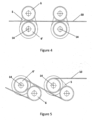
- FIGS 4 and 5 illustrate a further embodiment of the invention.
- the rotatable support 5 for the sheaves 6, 6' here takes the form of an arm of plate material.
- the components for rotating the support 5 are located at one end of the support and take a form similar to that of Figure 3 , e.g. with a slewing ring and driving motor.
- One of the sheaves 6' is arranged with its axis of rotation coincident with the axis of rotation 14 of the support arm 5.
- the other sheave 6 is arranged at the opposite end of the support arm.
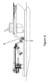
- Figure 6 shows a ship provided with a crane and a device 8 according to the invention oriented vertically and mounted pivotally about a vertical axis at the side of the ship so that it may be swung outwards to reach over the side of the ship.
- the crane may move to place its hoisting wire sidewise into the gap between the sheaves 6, 6' in their inactivated condition and have the wire engaged by the sheaves by moving them to their activated condition.
- the tensioning devices according to the invention may be arranged so that all axes of rotation of the sheaves and turntables are substantially horizontal, or parallel to the deck of the vessel, or it may be arranged so that the main body is substantially horisontal, or parallel to the deck and the axes of rotation are substantially vertical.
- tensioning units may be operated independently. To avoid unnecessary bending of the rope, it may be preferred to activate the number of tensioning units that are necessary for the given task, and leave the remaining units in their inactivated position.
- breaking powder of the motors may be transformer to usable energy, e.g. electrical energy that may be used for other purposes on board the vessel.
- usable energy e.g. electrical energy that may be used for other purposes on board the vessel.
- present invention is not limited to the exemplifying embodiments described herein, by may be varied and modified by the skilled person within the scope of the following claims.
Landscapes
- Engineering & Computer Science (AREA)
- Mechanical Engineering (AREA)
- Jib Cranes (AREA)
- Ropes Or Cables (AREA)
- Emergency Lowering Means (AREA)
- Lift-Guide Devices, And Elevator Ropes And Cables (AREA)
Claims (8)
- Dispositif pour la mise en tension d'un câble, le dispositif comprenant deux ou plusieurs poulies (6, 6') mises en oeuvre par un moteur, où un câble (10) à mettre en tension peut être agencé de sorte qu'il repose de manière séquentielle contre la surface de poulie des poulies du dispositif, les poulies (6, 6') étant mobiles afin de faire varier l'angle de contact du câble autour de chaque poulie, les poulies (6, 6') étant agencées en paires sur un support rotatif (2), ledit support rotatif (2) étant rotatif entre une première position de rotation dans laquelle le câble (10) peut passer librement entre la paire de poulies (6, 6'), et une deuxième position de rotation, variable, dans laquelle le câble (10) a été enroulé jusqu'à un angle de contact sensiblement égal autour des poulies, caractérisé en ce que chaque poulie (6, 6') est mise en oeuvre par un moteur (7, 7') distinct ayant une capacité de rupture, et en ce qu'un palier à éléments roulants sous la forme d'une bague d'orientation est agencé entre le support rotatif (2) et un corps principal stationnaire (1) pour fournir une connexion rotative entre elles.
- Dispositif selon la revendication 1, dans lequel l'angle de contact maximal est dans la plage de 210 à 250 degrés pour chaque poulie.
- Dispositif selon la revendication 1 ou 2, comprenant en outre des poulies de guidage (9, 9').
- Dispositif selon l'une quelconque des revendications précédentes, dans lequel les moteurs (7, 7') des poulies sont mis en oeuvre indépendamment.
- Dispositif selon l'une quelconque des revendications précédentes, dans lequel les supports rotatifs (2) sont mis en oeuvre indépendamment.
- Dispositif selon l'une quelconque des revendications 1 à 4, dans lequel deux ou plusieurs supports rotatifs (2) sont mis en oeuvre par un dispositif d'actionnement commun (3).
- Dispositif selon l'une quelconque des revendications précédentes, dans lequel l'axe de rotation d'une des poulies (6') coïncide avec l'axe de rotation (14) du support rotatif (5).
- Dispositif selon l'une quelconque des revendications précédentes, dans lequel le dispositif est orienté verticalement et est monté de manière pivotante autour d'un axe vertical au niveau du flanc d'un navire de sorte qu'il peut être déporté par rapport au flanc du navire.
Priority Applications (2)
| Application Number | Priority Date | Filing Date | Title |
|---|---|---|---|
| PL12714090T PL2688832T3 (pl) | 2011-03-23 | 2012-03-23 | Urządzenie do zaciskania liny |
| HRP20150614TT HRP20150614T1 (hr) | 2011-03-23 | 2012-03-23 | Uređaj za zatezanje užeta |
Applications Claiming Priority (2)
| Application Number | Priority Date | Filing Date | Title |
|---|---|---|---|
| NO20110436 | 2011-03-23 | ||
| PCT/NO2012/000031 WO2012128637A1 (fr) | 2011-03-23 | 2012-03-23 | Dispositif pour serrer une corde |
Publications (3)
| Publication Number | Publication Date |
|---|---|
| EP2688832A1 EP2688832A1 (fr) | 2014-01-29 |
| EP2688832B1 EP2688832B1 (fr) | 2015-03-11 |
| EP2688832B2 true EP2688832B2 (fr) | 2023-05-10 |
Family
ID=45953206
Family Applications (1)
| Application Number | Title | Priority Date | Filing Date |
|---|---|---|---|
| EP12714090.3A Active EP2688832B2 (fr) | 2011-03-23 | 2012-03-23 | Dispositif pour serrer une corde |
Country Status (11)
| Country | Link |
|---|---|
| US (1) | US9321617B2 (fr) |
| EP (1) | EP2688832B2 (fr) |
| BR (1) | BR112013024071B1 (fr) |
| CA (1) | CA2830316C (fr) |
| DK (1) | DK2688832T3 (fr) |
| ES (1) | ES2539036T3 (fr) |
| HR (1) | HRP20150614T1 (fr) |
| NO (1) | NO334128B1 (fr) |
| PL (1) | PL2688832T3 (fr) |
| PT (1) | PT2688832E (fr) |
| WO (1) | WO2012128637A1 (fr) |
Families Citing this family (9)
| Publication number | Priority date | Publication date | Assignee | Title |
|---|---|---|---|---|
| NO334789B1 (no) * | 2011-04-04 | 2014-05-26 | Rolls Royce Marine As | Anordning for spenning av et tau eller en kabel |
| US9834417B2 (en) | 2012-10-17 | 2017-12-05 | Fairfield Industries Incorporated | Payload control apparatus, method, and applications |
| NO341272B1 (no) * | 2015-07-01 | 2017-10-02 | Shm Solutions As | Apparat til å betjene en line samt fremgangsmåte for anvendelse av samme |
| GB2549488A (en) * | 2016-04-18 | 2017-10-25 | David Screaton Lee | Active heave compensation apparatus |
| EP3459903B1 (fr) | 2017-09-26 | 2020-06-24 | Robert Bosch GmbH | Compensateur pour l'amortissement ou la mise en tension et compensation de longueur active d'un moyen de traction souple |
| US10669138B2 (en) * | 2018-02-06 | 2020-06-02 | Benton Frederick Baugh | Method of providing preload for a dual drum traction winch |
| CN110937535B (zh) * | 2019-11-15 | 2021-12-07 | 兰州万里航空机电有限责任公司 | 一种用于伞带回收电动设备的钢丝绳张力调节器 |
| NO346382B1 (en) * | 2020-09-24 | 2022-07-04 | Bjoershol Oeyvind | A line lock, a handling system and a method for locking a mooring line using the line lock |
| US11078984B1 (en) * | 2020-10-05 | 2021-08-03 | United States Of America As Represented By The Administrator Of Nasa | Structure movement damping system using tension element |
Citations (1)
| Publication number | Priority date | Publication date | Assignee | Title |
|---|---|---|---|---|
| US2756872A (en) † | 1956-07-31 | hartley |
Family Cites Families (27)
| Publication number | Priority date | Publication date | Assignee | Title |
|---|---|---|---|---|
| US2756873A (en) * | 1956-07-31 | hartley etal a | ||
| FR448630A (fr) * | 1912-09-24 | 1913-02-05 | Societe Vernes Guinet Sigros & Cie | Treuil à friction |
| US1140460A (en) * | 1913-12-10 | 1915-05-25 | George A Jaeger | Tracker and tension device. |
| US2791910A (en) | 1955-02-16 | 1957-05-14 | Goodman Mfg Co | Take-up device for v-belt drives |
| DE1107311B (de) * | 1956-11-27 | 1961-05-25 | Telegraph Constr & Maintenance | Verfahren und Vorrichtung zum Regeln der Bewegung eines Seekabels beim Auslegen oderEinholen |
| US3246818A (en) | 1964-01-08 | 1966-04-19 | Gillette Co | Tension bridle |
| DE1474231A1 (de) * | 1964-01-16 | 1969-05-22 | Luetcke Werner Walter | Automatische Spulmaschine |
| US3420459A (en) * | 1967-07-03 | 1969-01-07 | Anaconda Wire & Cable Co | Wire take-up |
| US3722776A (en) * | 1971-05-03 | 1973-03-27 | Bwg Bergwerk Walzwerk | Roll system for tensioning elongated work pieces |
| DE2335416A1 (de) * | 1973-04-09 | 1974-10-24 | Avon Rubber Co Ltd | Vorrichtung zum zufuehren und spannen von draehten fuer drahtverstaerkte einlagen, insbesondere fuer fahrzeugreifen |
| US4065101A (en) | 1976-10-07 | 1977-12-27 | Korkut Mehmet D | Torsion spool |
| SE429212B (sv) * | 1978-04-25 | 1983-08-22 | Tetra Pak Int | Anordning for bearbetning av lopande materialbana |
| NZ203705A (en) * | 1982-04-30 | 1986-04-11 | Murdock Machine & Eng | Tension damper for mooring rope |
| US4846446A (en) * | 1982-04-30 | 1989-07-11 | Lockheed Corporation | Rope tension damper |
| US4760992A (en) * | 1982-04-30 | 1988-08-02 | Lockheed Corporation | Rope tension damper |
| US4576100A (en) * | 1982-09-17 | 1986-03-18 | Amca International Corporation | Crane for nuclear waste handling facilities |
| US5906325A (en) | 1997-10-16 | 1999-05-25 | Northrop Grumman Corporation | Self-synchronizing pulley/winch apparatus and operating method for cable having electronic or other protruding elements spaced along its length |
| NO324416B1 (no) | 1998-04-21 | 2007-10-08 | Odim Asa | Flerskaren tractionvinsj |
| NO309646B1 (no) | 1999-01-27 | 2001-03-05 | Odim Holding Asa | Strekkavlastningsanordning |
| US7134645B1 (en) * | 2003-02-05 | 2006-11-14 | Advanced Design Consulting Usa | Winch assembly for use with synthetic ropes |
| US7766307B2 (en) | 2007-03-16 | 2010-08-03 | Mactaggart, Scott (Holdings) Limited | Cable handling device |
| FR2919280B1 (fr) * | 2007-07-24 | 2010-02-19 | Soc Et De Rech Et Dev D Automa | Treuil pour la traction de cables, en particulier de cables synthetiques employes en offshore. |
| NO330246B1 (no) | 2009-02-25 | 2011-03-14 | Odim Asa | Fremgangsmåte og anordning for håndtering av tau |
| DE102009035197A1 (de) * | 2009-07-29 | 2011-02-17 | Liebherr-Werk Biberach Gmbh | Antriebseinheit mit Überlastschutz zum Antrieb eines Zahnkranzes |
| DK2529455T3 (en) | 2010-01-25 | 2015-01-19 | Octio As | Injury Prevention in underwater cables and the like elements during laying or picking up |
| NO331673B1 (no) | 2010-05-07 | 2012-02-20 | Triplex As | Strammingsregulator for et ankerlinetau |
| NO334789B1 (no) * | 2011-04-04 | 2014-05-26 | Rolls Royce Marine As | Anordning for spenning av et tau eller en kabel |
-
2012
- 2012-03-23 WO PCT/NO2012/000031 patent/WO2012128637A1/fr not_active Ceased
- 2012-03-23 EP EP12714090.3A patent/EP2688832B2/fr active Active
- 2012-03-23 PL PL12714090T patent/PL2688832T3/pl unknown
- 2012-03-23 HR HRP20150614TT patent/HRP20150614T1/hr unknown
- 2012-03-23 US US14/003,441 patent/US9321617B2/en active Active
- 2012-03-23 CA CA2830316A patent/CA2830316C/fr active Active
- 2012-03-23 NO NO20120366A patent/NO334128B1/no unknown
- 2012-03-23 PT PT127140903T patent/PT2688832E/pt unknown
- 2012-03-23 BR BR112013024071-7A patent/BR112013024071B1/pt active IP Right Grant
- 2012-03-23 ES ES12714090.3T patent/ES2539036T3/es active Active
- 2012-03-23 DK DK12714090.3T patent/DK2688832T3/da active
Patent Citations (1)
| Publication number | Priority date | Publication date | Assignee | Title |
|---|---|---|---|---|
| US2756872A (en) † | 1956-07-31 | hartley |
Also Published As
| Publication number | Publication date |
|---|---|
| PL2688832T3 (pl) | 2015-08-31 |
| CA2830316C (fr) | 2016-05-31 |
| CA2830316A1 (fr) | 2012-09-27 |
| BR112013024071B1 (pt) | 2021-04-20 |
| EP2688832A1 (fr) | 2014-01-29 |
| NO334128B1 (no) | 2013-12-16 |
| HRP20150614T1 (hr) | 2015-07-17 |
| PT2688832E (pt) | 2015-06-18 |
| DK2688832T3 (da) | 2015-06-22 |
| NO20120366A1 (no) | 2012-09-24 |
| US20130341453A1 (en) | 2013-12-26 |
| EP2688832B1 (fr) | 2015-03-11 |
| BR112013024071A2 (pt) | 2016-12-13 |
| ES2539036T3 (es) | 2015-06-25 |
| WO2012128637A1 (fr) | 2012-09-27 |
| US9321617B2 (en) | 2016-04-26 |
Similar Documents
| Publication | Publication Date | Title |
|---|---|---|
| EP2688832B2 (fr) | Dispositif pour serrer une corde | |
| EP2054335B1 (fr) | Compensateur actif direct de mouvement de tangage actif/passif à poulie unique | |
| US8931350B2 (en) | Rope test stand | |
| EP2694427B1 (fr) | Dispositif de tensionnement | |
| DK2521685T3 (en) | GAME DEVICE | |
| US9850112B2 (en) | Load bearing apparatus and method | |
| JP2020059604A (ja) | ケーブル巻き上げ操作についてのホイストシステム、ケーブルドラムアセンブリ、およびケーブルのもつれを検出する方法 | |
| WO2002038481A1 (fr) | Dispositif de compensation d'allongement de cable principal pour ascenseur | |
| US4227677A (en) | Anti-sway device for hoists and cranes | |
| WO2008100150A1 (fr) | Treuil |
Legal Events
| Date | Code | Title | Description |
|---|---|---|---|
| PUAI | Public reference made under article 153(3) epc to a published international application that has entered the european phase |
Free format text: ORIGINAL CODE: 0009012 |
|
| 17P | Request for examination filed |
Effective date: 20130907 |
|
| AK | Designated contracting states |
Kind code of ref document: A1 Designated state(s): AL AT BE BG CH CY CZ DE DK EE ES FI FR GB GR HR HU IE IS IT LI LT LU LV MC MK MT NL NO PL PT RO RS SE SI SK SM TR |
|
| DAX | Request for extension of the european patent (deleted) | ||
| RIC1 | Information provided on ipc code assigned before grant |
Ipc: B66D 1/52 20060101ALI20140930BHEP Ipc: B66D 1/50 20060101ALI20140930BHEP Ipc: B66D 1/74 20060101AFI20140930BHEP |
|
| GRAP | Despatch of communication of intention to grant a patent |
Free format text: ORIGINAL CODE: EPIDOSNIGR1 |
|
| INTG | Intention to grant announced |
Effective date: 20141216 |
|
| GRAS | Grant fee paid |
Free format text: ORIGINAL CODE: EPIDOSNIGR3 |
|
| GRAA | (expected) grant |
Free format text: ORIGINAL CODE: 0009210 |
|
| AK | Designated contracting states |
Kind code of ref document: B1 Designated state(s): AL AT BE BG CH CY CZ DE DK EE ES FI FR GB GR HR HU IE IS IT LI LT LU LV MC MK MT NL NO PL PT RO RS SE SI SK SM TR |
|
| REG | Reference to a national code |
Ref country code: GB Ref legal event code: FG4D |
|
| REG | Reference to a national code |
Ref country code: CH Ref legal event code: EP |
|
| REG | Reference to a national code |
Ref country code: IE Ref legal event code: FG4D |
|
| REG | Reference to a national code |
Ref country code: AT Ref legal event code: REF Ref document number: 715212 Country of ref document: AT Kind code of ref document: T Effective date: 20150415 |
|
| REG | Reference to a national code |
Ref country code: DE Ref legal event code: R096 Ref document number: 602012005849 Country of ref document: DE Effective date: 20150423 |
|
| REG | Reference to a national code |
Ref country code: FR Ref legal event code: PLFP Year of fee payment: 4 |
|
| REG | Reference to a national code |
Ref country code: HR Ref legal event code: TUEP Ref document number: P20150614 Country of ref document: HR Ref country code: RO Ref legal event code: EPE |
|
| REG | Reference to a national code |
Ref country code: NL Ref legal event code: T3 |
|
| REG | Reference to a national code |
Ref country code: PT Ref legal event code: SC4A Free format text: AVAILABILITY OF NATIONAL TRANSLATION Effective date: 20150611 |
|
| REG | Reference to a national code |
Ref country code: DK Ref legal event code: T3 Effective date: 20150615 |
|
| REG | Reference to a national code |
Ref country code: SE Ref legal event code: TRGR |
|
| REG | Reference to a national code |
Ref country code: ES Ref legal event code: FG2A Ref document number: 2539036 Country of ref document: ES Kind code of ref document: T3 Effective date: 20150625 |
|
| REG | Reference to a national code |
Ref country code: HR Ref legal event code: T1PR Ref document number: P20150614 Country of ref document: HR |
|
| PG25 | Lapsed in a contracting state [announced via postgrant information from national office to epo] |
Ref country code: NO Free format text: LAPSE BECAUSE OF FAILURE TO SUBMIT A TRANSLATION OF THE DESCRIPTION OR TO PAY THE FEE WITHIN THE PRESCRIBED TIME-LIMIT Effective date: 20150611 Ref country code: LT Free format text: LAPSE BECAUSE OF FAILURE TO SUBMIT A TRANSLATION OF THE DESCRIPTION OR TO PAY THE FEE WITHIN THE PRESCRIBED TIME-LIMIT Effective date: 20150311 Ref country code: FI Free format text: LAPSE BECAUSE OF FAILURE TO SUBMIT A TRANSLATION OF THE DESCRIPTION OR TO PAY THE FEE WITHIN THE PRESCRIBED TIME-LIMIT Effective date: 20150311 |
|
| REG | Reference to a national code |
Ref country code: AT Ref legal event code: MK05 Ref document number: 715212 Country of ref document: AT Kind code of ref document: T Effective date: 20150311 |
|
| REG | Reference to a national code |
Ref country code: LT Ref legal event code: MG4D |
|
| PG25 | Lapsed in a contracting state [announced via postgrant information from national office to epo] |
Ref country code: GR Free format text: LAPSE BECAUSE OF FAILURE TO SUBMIT A TRANSLATION OF THE DESCRIPTION OR TO PAY THE FEE WITHIN THE PRESCRIBED TIME-LIMIT Effective date: 20150612 Ref country code: LV Free format text: LAPSE BECAUSE OF FAILURE TO SUBMIT A TRANSLATION OF THE DESCRIPTION OR TO PAY THE FEE WITHIN THE PRESCRIBED TIME-LIMIT Effective date: 20150311 Ref country code: RS Free format text: LAPSE BECAUSE OF FAILURE TO SUBMIT A TRANSLATION OF THE DESCRIPTION OR TO PAY THE FEE WITHIN THE PRESCRIBED TIME-LIMIT Effective date: 20150311 |
|
| REG | Reference to a national code |
Ref country code: PL Ref legal event code: T3 |
|
| PG25 | Lapsed in a contracting state [announced via postgrant information from national office to epo] |
Ref country code: EE Free format text: LAPSE BECAUSE OF FAILURE TO SUBMIT A TRANSLATION OF THE DESCRIPTION OR TO PAY THE FEE WITHIN THE PRESCRIBED TIME-LIMIT Effective date: 20150311 Ref country code: CZ Free format text: LAPSE BECAUSE OF FAILURE TO SUBMIT A TRANSLATION OF THE DESCRIPTION OR TO PAY THE FEE WITHIN THE PRESCRIBED TIME-LIMIT Effective date: 20150311 Ref country code: SK Free format text: LAPSE BECAUSE OF FAILURE TO SUBMIT A TRANSLATION OF THE DESCRIPTION OR TO PAY THE FEE WITHIN THE PRESCRIBED TIME-LIMIT Effective date: 20150311 |
|
| REG | Reference to a national code |
Ref country code: CH Ref legal event code: PL |
|
| PG25 | Lapsed in a contracting state [announced via postgrant information from national office to epo] |
Ref country code: AT Free format text: LAPSE BECAUSE OF FAILURE TO SUBMIT A TRANSLATION OF THE DESCRIPTION OR TO PAY THE FEE WITHIN THE PRESCRIBED TIME-LIMIT Effective date: 20150311 |
|
| REG | Reference to a national code |
Ref country code: DE Ref legal event code: R026 Ref document number: 602012005849 Country of ref document: DE |
|
| PLBI | Opposition filed |
Free format text: ORIGINAL CODE: 0009260 |
|
| PG25 | Lapsed in a contracting state [announced via postgrant information from national office to epo] |
Ref country code: IT Free format text: LAPSE BECAUSE OF FAILURE TO SUBMIT A TRANSLATION OF THE DESCRIPTION OR TO PAY THE FEE WITHIN THE PRESCRIBED TIME-LIMIT Effective date: 20150311 |
|
| PLAX | Notice of opposition and request to file observation + time limit sent |
Free format text: ORIGINAL CODE: EPIDOSNOBS2 |
|
| 26 | Opposition filed |
Opponent name: ROLLS-ROYCE MARINE AS Effective date: 20151211 |
|
| PG25 | Lapsed in a contracting state [announced via postgrant information from national office to epo] |
Ref country code: LI Free format text: LAPSE BECAUSE OF NON-PAYMENT OF DUE FEES Effective date: 20150331 Ref country code: CH Free format text: LAPSE BECAUSE OF NON-PAYMENT OF DUE FEES Effective date: 20150331 Ref country code: MC Free format text: LAPSE BECAUSE OF FAILURE TO SUBMIT A TRANSLATION OF THE DESCRIPTION OR TO PAY THE FEE WITHIN THE PRESCRIBED TIME-LIMIT Effective date: 20150311 |
|
| PG25 | Lapsed in a contracting state [announced via postgrant information from national office to epo] |
Ref country code: SI Free format text: LAPSE BECAUSE OF FAILURE TO SUBMIT A TRANSLATION OF THE DESCRIPTION OR TO PAY THE FEE WITHIN THE PRESCRIBED TIME-LIMIT Effective date: 20150311 |
|
| REG | Reference to a national code |
Ref country code: FR Ref legal event code: PLFP Year of fee payment: 5 |
|
| PLBB | Reply of patent proprietor to notice(s) of opposition received |
Free format text: ORIGINAL CODE: EPIDOSNOBS3 |
|
| PG25 | Lapsed in a contracting state [announced via postgrant information from national office to epo] |
Ref country code: BE Free format text: LAPSE BECAUSE OF FAILURE TO SUBMIT A TRANSLATION OF THE DESCRIPTION OR TO PAY THE FEE WITHIN THE PRESCRIBED TIME-LIMIT Effective date: 20150311 |
|
| PG25 | Lapsed in a contracting state [announced via postgrant information from national office to epo] |
Ref country code: MT Free format text: LAPSE BECAUSE OF FAILURE TO SUBMIT A TRANSLATION OF THE DESCRIPTION OR TO PAY THE FEE WITHIN THE PRESCRIBED TIME-LIMIT Effective date: 20150311 |
|
| REG | Reference to a national code |
Ref country code: HR Ref legal event code: ODRP Ref document number: P20150614 Country of ref document: HR Payment date: 20170321 Year of fee payment: 6 |
|
| REG | Reference to a national code |
Ref country code: FR Ref legal event code: PLFP Year of fee payment: 6 |
|
| PGFP | Annual fee paid to national office [announced via postgrant information from national office to epo] |
Ref country code: DE Payment date: 20180925 Year of fee payment: 12 Ref country code: RO Payment date: 20170321 Year of fee payment: 6 |
|
| PG25 | Lapsed in a contracting state [announced via postgrant information from national office to epo] |
Ref country code: HU Free format text: LAPSE BECAUSE OF FAILURE TO SUBMIT A TRANSLATION OF THE DESCRIPTION OR TO PAY THE FEE WITHIN THE PRESCRIBED TIME-LIMIT; INVALID AB INITIO Effective date: 20120323 Ref country code: SM Free format text: LAPSE BECAUSE OF FAILURE TO SUBMIT A TRANSLATION OF THE DESCRIPTION OR TO PAY THE FEE WITHIN THE PRESCRIBED TIME-LIMIT Effective date: 20150311 Ref country code: BG Free format text: LAPSE BECAUSE OF FAILURE TO SUBMIT A TRANSLATION OF THE DESCRIPTION OR TO PAY THE FEE WITHIN THE PRESCRIBED TIME-LIMIT Effective date: 20150311 |
|
| PGFP | Annual fee paid to national office [announced via postgrant information from national office to epo] |
Ref country code: HR Payment date: 20170321 Year of fee payment: 6 Ref country code: PL Payment date: 20170320 Year of fee payment: 6 Ref country code: PT Payment date: 20170320 Year of fee payment: 6 Ref country code: IE Payment date: 20170322 Year of fee payment: 6 Ref country code: IS Payment date: 20170331 Year of fee payment: 6 Ref country code: DK Payment date: 20170328 Year of fee payment: 6 |
|
| PG25 | Lapsed in a contracting state [announced via postgrant information from national office to epo] |
Ref country code: CY Free format text: LAPSE BECAUSE OF FAILURE TO SUBMIT A TRANSLATION OF THE DESCRIPTION OR TO PAY THE FEE WITHIN THE PRESCRIBED TIME-LIMIT Effective date: 20150311 |
|
| PGFP | Annual fee paid to national office [announced via postgrant information from national office to epo] |
Ref country code: ES Payment date: 20170322 Year of fee payment: 6 |
|
| PG25 | Lapsed in a contracting state [announced via postgrant information from national office to epo] |
Ref country code: TR Free format text: LAPSE BECAUSE OF FAILURE TO SUBMIT A TRANSLATION OF THE DESCRIPTION OR TO PAY THE FEE WITHIN THE PRESCRIBED TIME-LIMIT Effective date: 20150311 |
|
| PG25 | Lapsed in a contracting state [announced via postgrant information from national office to epo] |
Ref country code: LU Free format text: LAPSE BECAUSE OF NON-PAYMENT OF DUE FEES Effective date: 20150323 |
|
| PG25 | Lapsed in a contracting state [announced via postgrant information from national office to epo] |
Ref country code: MK Free format text: LAPSE BECAUSE OF FAILURE TO SUBMIT A TRANSLATION OF THE DESCRIPTION OR TO PAY THE FEE WITHIN THE PRESCRIBED TIME-LIMIT Effective date: 20150311 |
|
| RDAF | Communication despatched that patent is revoked |
Free format text: ORIGINAL CODE: EPIDOSNREV1 |
|
| STAA | Information on the status of an ep patent application or granted ep patent |
Free format text: STATUS: THE PATENT HAS BEEN GRANTED |
|
| APBM | Appeal reference recorded |
Free format text: ORIGINAL CODE: EPIDOSNREFNO |
|
| APBP | Date of receipt of notice of appeal recorded |
Free format text: ORIGINAL CODE: EPIDOSNNOA2O |
|
| APAH | Appeal reference modified |
Free format text: ORIGINAL CODE: EPIDOSCREFNO |
|
| REG | Reference to a national code |
Ref country code: FR Ref legal event code: PLFP Year of fee payment: 7 |
|
| REG | Reference to a national code |
Ref country code: DE Ref legal event code: R119 Ref document number: 602012005849 Country of ref document: DE |
|
| APBQ | Date of receipt of statement of grounds of appeal recorded |
Free format text: ORIGINAL CODE: EPIDOSNNOA3O |
|
| REG | Reference to a national code |
Ref country code: DK Ref legal event code: EBP Effective date: 20180331 |
|
| PG25 | Lapsed in a contracting state [announced via postgrant information from national office to epo] |
Ref country code: SE Free format text: LAPSE BECAUSE OF NON-PAYMENT OF DUE FEES Effective date: 20180324 Ref country code: AL Free format text: LAPSE BECAUSE OF FAILURE TO SUBMIT A TRANSLATION OF THE DESCRIPTION OR TO PAY THE FEE WITHIN THE PRESCRIBED TIME-LIMIT Effective date: 20150311 Ref country code: RO Free format text: LAPSE BECAUSE OF NON-PAYMENT OF DUE FEES Effective date: 20180323 Ref country code: PT Free format text: LAPSE BECAUSE OF NON-PAYMENT OF DUE FEES Effective date: 20180924 |
|
| REG | Reference to a national code |
Ref country code: HR Ref legal event code: PBON Ref document number: P20150614 Country of ref document: HR Effective date: 20180323 |
|
| REG | Reference to a national code |
Ref country code: IE Ref legal event code: MM4A |
|
| PG25 | Lapsed in a contracting state [announced via postgrant information from national office to epo] |
Ref country code: DE Free format text: LAPSE BECAUSE OF NON-PAYMENT OF DUE FEES Effective date: 20181002 Ref country code: IS Free format text: LAPSE BECAUSE OF FAILURE TO SUBMIT A TRANSLATION OF THE DESCRIPTION OR TO PAY THE FEE WITHIN THE PRESCRIBED TIME-LIMIT Effective date: 20181001 Ref country code: IE Free format text: LAPSE BECAUSE OF NON-PAYMENT OF DUE FEES Effective date: 20180323 |
|
| PLAB | Opposition data, opponent's data or that of the opponent's representative modified |
Free format text: ORIGINAL CODE: 0009299OPPO |
|
| PG25 | Lapsed in a contracting state [announced via postgrant information from national office to epo] |
Ref country code: HR Free format text: LAPSE BECAUSE OF NON-PAYMENT OF DUE FEES Effective date: 20180323 |
|
| R26 | Opposition filed (corrected) |
Opponent name: ROLLS-ROYCE MARINE AS Effective date: 20151211 |
|
| PG25 | Lapsed in a contracting state [announced via postgrant information from national office to epo] |
Ref country code: DK Free format text: LAPSE BECAUSE OF NON-PAYMENT OF DUE FEES Effective date: 20180331 |
|
| REG | Reference to a national code |
Ref country code: ES Ref legal event code: FD2A Effective date: 20190909 |
|
| PG25 | Lapsed in a contracting state [announced via postgrant information from national office to epo] |
Ref country code: ES Free format text: LAPSE BECAUSE OF NON-PAYMENT OF DUE FEES Effective date: 20180324 |
|
| PG25 | Lapsed in a contracting state [announced via postgrant information from national office to epo] |
Ref country code: PL Free format text: LAPSE BECAUSE OF NON-PAYMENT OF DUE FEES Effective date: 20180323 |
|
| APBU | Appeal procedure closed |
Free format text: ORIGINAL CODE: EPIDOSNNOA9O |
|
| REG | Reference to a national code |
Ref country code: FR Ref legal event code: PLFP Year of fee payment: 11 |
|
| PUAH | Patent maintained in amended form |
Free format text: ORIGINAL CODE: 0009272 |
|
| STAA | Information on the status of an ep patent application or granted ep patent |
Free format text: STATUS: PATENT MAINTAINED AS AMENDED |
|
| 27A | Patent maintained in amended form |
Effective date: 20230510 |
|
| AK | Designated contracting states |
Kind code of ref document: B2 Designated state(s): AL AT BE BG CH CY CZ DE DK EE ES FI FR GB GR HR HU IE IS IT LI LT LU LV MC MK MT NL NO PL PT RO RS SE SI SK SM TR |
|
| REG | Reference to a national code |
Ref country code: DE Ref legal event code: R102 Ref document number: 602012005849 Country of ref document: DE |
|
| REG | Reference to a national code |
Ref country code: NL Ref legal event code: FP |
|
| PGFP | Annual fee paid to national office [announced via postgrant information from national office to epo] |
Ref country code: GB Payment date: 20260318 Year of fee payment: 15 |
|
| PGFP | Annual fee paid to national office [announced via postgrant information from national office to epo] |
Ref country code: NL Payment date: 20260319 Year of fee payment: 15 |
|
| PGFP | Annual fee paid to national office [announced via postgrant information from national office to epo] |
Ref country code: FR Payment date: 20260317 Year of fee payment: 15 |