EP2689100B1 - Vorrichtung und verfahren zur positionierung eines fluidisierten stopfmaterials in einem ölbohrloch oder einem gasbohrloch - Google Patents
Vorrichtung und verfahren zur positionierung eines fluidisierten stopfmaterials in einem ölbohrloch oder einem gasbohrloch Download PDFInfo
- Publication number
- EP2689100B1 EP2689100B1 EP12760353.8A EP12760353A EP2689100B1 EP 2689100 B1 EP2689100 B1 EP 2689100B1 EP 12760353 A EP12760353 A EP 12760353A EP 2689100 B1 EP2689100 B1 EP 2689100B1
- Authority
- EP
- European Patent Office
- Prior art keywords
- casing
- carrier body
- well
- plugging material
- displacement member
- Prior art date
- Legal status (The legal status is an assumption and is not a legal conclusion. Google has not performed a legal analysis and makes no representation as to the accuracy of the status listed.)
- Active
Links
Images




Classifications
-
- E—FIXED CONSTRUCTIONS
- E21—EARTH OR ROCK DRILLING; MINING
- E21B—EARTH OR ROCK DRILLING; OBTAINING OIL, GAS, WATER, SOLUBLE OR MELTABLE MATERIALS OR A SLURRY OF MINERALS FROM WELLS
- E21B27/00—Containers for collecting or depositing substances in boreholes or wells, e.g. bailers, baskets or buckets for collecting mud or sand; Drill bits with means for collecting substances, e.g. valve drill bits
- E21B27/02—Dump bailers, i.e. containers for depositing substances, e.g. cement or acids
-
- E—FIXED CONSTRUCTIONS
- E21—EARTH OR ROCK DRILLING; MINING
- E21B—EARTH OR ROCK DRILLING; OBTAINING OIL, GAS, WATER, SOLUBLE OR MELTABLE MATERIALS OR A SLURRY OF MINERALS FROM WELLS
- E21B33/00—Sealing or packing boreholes or wells
- E21B33/10—Sealing or packing boreholes or wells in the borehole
- E21B33/13—Methods or devices for cementing, for plugging holes, crevices or the like
- E21B33/14—Methods or devices for cementing, for plugging holes, crevices or the like for cementing casings into boreholes
-
- E—FIXED CONSTRUCTIONS
- E21—EARTH OR ROCK DRILLING; MINING
- E21B—EARTH OR ROCK DRILLING; OBTAINING OIL, GAS, WATER, SOLUBLE OR MELTABLE MATERIALS OR A SLURRY OF MINERALS FROM WELLS
- E21B17/00—Drilling rods or pipes; Flexible drill strings; Kellies; Drill collars; Sucker rods; Cables; Casings; Tubings
- E21B17/22—Rods or pipes with helical structure
-
- E—FIXED CONSTRUCTIONS
- E21—EARTH OR ROCK DRILLING; MINING
- E21B—EARTH OR ROCK DRILLING; OBTAINING OIL, GAS, WATER, SOLUBLE OR MELTABLE MATERIALS OR A SLURRY OF MINERALS FROM WELLS
- E21B33/00—Sealing or packing boreholes or wells
- E21B33/10—Sealing or packing boreholes or wells in the borehole
- E21B33/13—Methods or devices for cementing, for plugging holes, crevices or the like
-
- E—FIXED CONSTRUCTIONS
- E21—EARTH OR ROCK DRILLING; MINING
- E21B—EARTH OR ROCK DRILLING; OBTAINING OIL, GAS, WATER, SOLUBLE OR MELTABLE MATERIALS OR A SLURRY OF MINERALS FROM WELLS
- E21B33/00—Sealing or packing boreholes or wells
- E21B33/10—Sealing or packing boreholes or wells in the borehole
- E21B33/13—Methods or devices for cementing, for plugging holes, crevices or the like
- E21B33/134—Bridging plugs
-
- E—FIXED CONSTRUCTIONS
- E21—EARTH OR ROCK DRILLING; MINING
- E21B—EARTH OR ROCK DRILLING; OBTAINING OIL, GAS, WATER, SOLUBLE OR MELTABLE MATERIALS OR A SLURRY OF MINERALS FROM WELLS
- E21B37/00—Methods or apparatus for cleaning boreholes or wells
- E21B37/02—Scrapers specially adapted therefor
Definitions
- the present disclosure relates to an apparatus for use when plugging a well within the petroleum industry. More particularly, it relates to an apparatus for use when positioning a fluidized plugging material in an oil well or a gas well which is lined with a casing, the apparatus including: a driving body; a carrier body defined by an indefinite side portion extending between a first end portion and a second end portion, the carrier body being arranged to be set in motion by the driving body; and at least one displacement member arranged on the carrier body.
- the fluidized plugging material usually comprises a cement slurry for the formation of a hardenable cement plug. But it is to be understood that the fluidized plugging material may comprise a fluidized unconsolidated material for the formation of an unconsolidated-material plug. The description that follows will be directed, to a great extent, towards a cement plug. However, the present invention is also well suited for positioning an unconsolidated-material plug.
- the extent of the plug in the longitudinal direction of the well is typically 50 metres, but is dependent on international, national or oil/gas contractors' internal requirements.
- the purpose of the present invention is to provide an apparatus and a method for providing a complete and reliable attachment of a fluidized plugging material in an oil well or a gas well. This is achieved by providing sufficient contact between the surface of the bore to be plugged and the plugging material.
- the apparatus and the method may be used both when plugging a non-perforated portion of a casing, when plugging a perforated casing, in which the plugging material fills most of the annulus between the formation and the centre of the casing, as well as when plugging a so-called open-hole section.
- an apparatus and a method for agitating a cement slurry in an annulus defined between a formation wall and a casing in a well are known.
- the apparatus includes a sleeve which is provided with an agitating device and which is arranged to rotate relative to the casing.
- the apparatus is placed on the outside of a portion of the casing.
- the cementing tool for ensuring sufficient sealing of an annulus between a riser and a casing is known.
- the cementing tool is constituted by a pipe piece which has flow-directing rigid ribs welded thereon to provide a turbulent flow between the riser and the casing when the pipe piece is set in rotation.
- the apparatus includes helical rigid blades welded on or otherwise attached to a completion tool.
- the invention has for its object to remedy or reduce at least one of the drawbacks of the prior art or at least provide a useful alternative to the prior art.
- an apparatus for use when positioning a fluidized plugging material in an oil well or a gas well lined with a casing including:
- the displacement member will provide a pressure change in the fluidized plugging material.
- the driving body may be a pipe string which is arranged to be set in rotation around a longitudinal axis of the casing, so that the movement of the apparatus is a rotational movement around the longitudinal axis of the casing.
- the driving body may be a motor which is positioned in or in connection with the apparatus and which is supplied with power from the surface of the well.
- the displacement member may be a blade.
- the free end portion of the blade is arranged to exhibit a deflection relative to a central contact portion between the blade and the carrier body. This has the effect of the displacement member exhibiting a "spatula effect" wherein the plugging material is pressed or "spread" against the internal surface of the casing.
- the central contact portion between the blade and the carrier body will also be referred to as an attachment portion, independently of whether the blade or a displacement member of some other kind is attached on the outside of or in the carrier body, or whether the displacement member is made in one piece with the carrier body.
- the apparatus may be formed in such a way that, by rotation, the carrier body and the at least one blade circumscribe a circle which has a diameter that is larger than the internal diameter of the casing. Thereby, even as the apparatus is being positioned in the casing, the at least one blade will be brought to assume a curvature.
- the projecting end portion of the blade may abut against the internal surface of the casing also after the apparatus has been set in rotation. But the blade could also be exposed to such a great force from the plugging material that it bends to such a great extent that it does not abut against the internal surface of the casing.
- the apparatus is formed in such a way that, by rotation, the carrier body and the at least one blade circumscribe a circle which has a diameter which is equal to or smaller than the internal diameter of the casing.
- the at least one blade may be arranged in such a way at the carrier body that the longitudinal axis of the blade extends parallel to a longitudinal axis of the carrier body.
- the longitudinal axis of the at least one blade extends at an angle relative to the longitudinal axis of the carrier body.
- the driving body may be a reciprocating driving means which is arranged to provide a to-and-fro movement of the at least one displacement member along the longitudinal axis of the casing.
- a reciprocating driving means it may be an advantage if the displacement member is a collar-shaped body.
- the free end portion of the collar-shaped body may, at least when moving, be arranged to exhibit a deflection relative to a central contact portion between the blade and the carrier body. This has the effect of the displacement member exhibiting a "spatula effect" against the internal surface of the casing, as explained above.
- the central contact portion between the blade and the carrier body will also be referred to as the attachment portion.
- the collar-shaped body extends in a helix around the carrier body. This has the effect of the fluidized plugging material being brought to move around the longitudinal axis of the casing in addition to moving along the longitudinal axis of the casing.
- the collar-shaped body extends at least 360° around the carrier body, so that the displacement member will work against the entire circumference of the internal surface of the casing. If the driving body is arranged to impart a reciprocating motion to the carrier body, both along the longitudinal axis of the casing and around the longitudinal axis of the casing, the collar-shaped body may extend less than 360° around the carrier body.
- the collar-shaped body may be formed in one piece or then it may be formed of at least two collar sector elements.
- the at least two collar sector elements may or may not be formed in such a way that they partly overlap.
- At least one of the collar sector elements may be provided with a hinged attachment portion, so that the free end portion is allowed to be brought in towards the carrier body when the apparatus is moved in one of the backward or forward movements.
- This "jellyfish motion” has the effect of the collar sector elements providing full effect only in one of the backward and forward movements. Such a “jellyfish motion” is particularly useful in the cases in which it is desirable to provide an increased differential pressure between two portions of the column of the fluidized plugging material.
- the fluidized plugging material may be a hardenable material, such as of the kind that is cement-based, for example.
- a hardenable material such as of the kind that is cement-based, for example.
- the carrier body may have a cylindrical shape.
- the apparatus is provided with a carrier body which, in one portion, has a larger external diameter than another portion of the carrier body. Said different diameters are preferably in portions from which the at least one displacement member projects, and may provide different flow rates along the apparatus.
- the at least one displacement member may include two or more spaced-apart displacement members.
- the displacement members may be arranged substantially parallel to each other, or the displacement members may be arranged non-parallel.
- the longitudinal axis of at least one of the blades may be arranged parallel to the longitudinal axis of the carrier body, whereas the longitudinal axis of at least one other of the blades may be arranged at an angle relative to a longitudinal axis of the carrier body.
- the apparatus may be constituted by several apparatuses arranged in series or in a so-called stack. Such an apparatus may be assembled from apparatuses having any kind of displacement members as described herein, or a combination thereof.
- the apparatus according to the present invention may thus be used both when permanently or temporarily plugging a casing which is provided with perforations, wherein movement of the apparatus drives a portion of a fluidized plugging material out through the perforations and to an outside of the casing, and when permanently or temporarily plugging a non-perforated casing, wherein movement of the apparatus drives the fluidized plugging material into engagement with the internal surface of the casing.
- a method for providing a permanent or temporary plug in a casing in a well wherein the plug is provided by means of a fluidized plugging material which is carried into the well from a surface, the method including the steps of: moving the apparatus according to the first aspect of the invention into the well; setting the apparatus in motion and supplying the fluidized plugging material from the surface of the well; continuing the movement for a predetermined time after all the plugging material has been supplied; and pulling the apparatus out of the well.
- the apparatus By placing the apparatus on an inside of the casing and, at the same time, providing one or more displacement members exhibiting a deflection relative to the attachment portion of the blade, as explained above, the free end portion of the displacement member, facing the internal surface of the casing, will exhibit a lag relative to the attachment portion of the displacement member. This lag turns out to be very favourable for pressing or "spreading" the plugging material against the inside of the casing.
- the casing, into which the apparatus according to the first aspect is run, may be non-perforated or perforated.
- the internal surface of a non-perforated casing may be contaminated with chemicals such as an oil film, for example, and/or by contamination of a more mechanical kind, such as rust particles, for example.
- This contamination may occur in one or more sections of the portion of the casing to which a plugging material is to be supplied, or in the entire portion of the casing to which a plugging material is to be supplied.
- This contamination may result in the engagement or adhesion between the plugging material, which may be cement-based, and the casing not being sufficiently strong.
- the apparatus and method according to the invention are also well suited for plugging a so-called open-hole section of a well.
- the flow of the fluidized plugging material provided by means of the apparatus will drive the plugging material against the formation in the open well section and, thus, provide a sufficient distribution of the plugging material in the entire cross section of the wellbore.
- This is particularly important in high-deviation wells, or horizontal well sections, in which the plugging material normally has a considerably greater density than the fluid present in the well. In such regions, the plugging material will settle at the bottom of the well path (on the low side of the cross section of the well) and may thus form a passage on the high side of the cross section of the well.
- an apparatus according to the first aspect of the disclosure is used when an open-hole section of a well is being plugged permanently or temporarily, wherein movement of the apparatus drives a fluidized plugging material into engagement against the formation of the well.
- the reference numeral 1 indicates an apparatus according to the present disclosure
- the apparatus 1 includes a carrier body 3 with at least one displacement member 5 arranged thereon.
- the displacement member 5 is radially defined by a contact portion 7 between the blade and the carrier body and a free end portion 9.
- the contact portion will be referred to, in what follows, as the attachment portion 7.
- the carrier body 3 is connected to a driving device 11 which is arranged to set the carrier body 3 and thus the displacement member 5 in motion.
- the apparatus 1 is designed to be positioned in a bore of a casing 13 placed in a well 15.
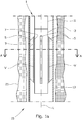
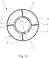
- Figures 1a and 1b show, respectively, a side view and a cross-sectional view seen through A-A in figure 1a of the apparatus 1 according to a first embodiment of the present invention.
- the section is shown only of the apparatus and of the casing.
- the at least one displacement member 5 is constituted by several elongated blades 5 (four shown in figure 1b ) extending parallel to a longitudinal axis L of the casing 13.
- the blades 5 are marked with dotted shading for clarity.
- An upper end portion of the apparatus 1 is connected, for example by means of a screw connection, to a pipe string 11 which is arranged to be set in rotation by means of a driving means known per se (not shown).
- the pipe string 11 constitutes said driving device 11.
- the apparatus 1 When the pipe string 11 is rotated, the apparatus 1 will also be set in a rotation R around the longitudinal axis L of the casing 13.
- the deflection may be achieved in several ways.
- a first way is to provide an apparatus 1 in which, by rotation, the carrier body 3 and the blades 5 circumscribe a circle that is larger than an internal diameter of the casing 13 into which it is to be moved. This assumes that the blades 5 are formed out of a flexible material which may deflect when being moved into the casing 13.
- a second way in which to achieve the desired deflection is to provide an apparatus in which, by rotation in the casing 13, the carrier body 3 and the blades 5 circumscribe a circle which has a diameter equal to or smaller than the internal diameter of the casing 13, but in which the blades 5 are formed out of a flexible material.
- a material may be selected from any bendable or flexible material which is suitable for placing a fluidized plugging material such as a cement slurry, for example, in a well 15.
- a fluidized plugging material such as a cement slurry
- a suitable material is a rubber-based material.
- Another example is a suitable steel.
- a blade based on rubber will exhibit a "windscreen-wiper effect” or a “spatula effect” against the internal surface of the casing 13.
- a blade 5 based on steel may exhibit a "steel-putty-knife effect”.
- a carrier body 3 may be provided with blades 5 made of the same material or of different materials.
- blades 5 may be made of the same material or of different materials.
- two of the blades 5 may be made of rubber, whereas the other two blades 5 may be made out of steel sheets.
- blades 5 are such as described above for the first way, whereas the other two of the four blades 5 (upper and lower blades) are as described above for the second way.
- the blades 5 of one carrier body 3 may be formed with identical blades 5.
- the fluidized plugging material may be a hardenable material, for example a cement-based material.
- the blades 5 may be provided with a weakening, for example in the form of a nicking V as shown in figures 1a and 1b .
- the load capacity of one or more of the blades 5 can thereby be set to be higher than the loads affecting the blades 5 by movement of the apparatus 1 in non-hardened plugging material, but lower than the loads affecting the blades 5 when an attempt is made to move the apparatus 1 in hardened plugging material, so that at least a portion of the blade 5 will break if the hardening process exceeds a predetermined level.
- Figure 2 shows an apparatus resembling the apparatus 1 shown in figure 1a , but with the difference that the displacement members 5 are constituted by elongated blades extending at an angle relative to the longitudinal axis L of the casing 13, in a partially helical shape around the external surface of the carrier body 3, that is.
- the free end portion 9 of the blades 5 are marked with dotted shading.
- the blades 5 in figure 2 may have the same design with respect to their radial extent from the carrier body 3 as the blades 5 mentioned in connection with figures 1a and 1b .
- Figure 3 shows an apparatus 1 which resembles the apparatus 1 shown in figure 2 , but in which the carrier body 3 is of a conical shape wherein an upper portion of the carrier body 3 has a larger external diameter than a lower portion of the carrier body 3. Because of the conical shape of the carrier body 3, the displacement members or blades 5 have a smaller radial extent in the upper portion of the apparatus 1 than the radial extent in the lower portion of the apparatus 1.
- the purpose of the design that is shown in figure 3 is to provide a variable annulus between the carrier body 3 and the casing 13, so that the fluidized plugging material will be displaced at different rates along the longitudinal axis of the apparatus 1. This has the effect of different pressure regimes arising, among other things.
- Figure 4 shows a portion of a well 15 which is provided with a casing 13.
- the casing 13 is provided with perforations 17 which have been provided, in the embodiment shown, by means of blasting charges.
- An annulus 19 is defined between a portion of the casing 13 and a formation 21.
- a plug 23 of a kind known per se is placed in a portion of the well 15 located lower in the well than the perforated portion of the casing 17.
- the purpose of the plug 23 is to provide a base or a support for a fluidized plugging material (not shown in figure 4 ) which is to be carried into the well 15.
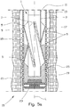
- Figure 5a shows the well 15 of figure 4 , but the apparatus 1 shown in figure 2 having been moved to a lower portion of the section of the well 15 which is to be plugged by means of a fluidized plugging material 25.
- the fluidized plugging material is supplied through a bore extending through the driving device 11 and the carrier body 3 while, at the same time, the apparatus 1 is being rotated around the longitudinal axis L.
- the blades 5 press or squeeze the plugging material 25 against the inside of the casing 13 and out through the perforations 17 and further into the annulus 19.
- Figure 5b shows the apparatus 1 of figure 5a as the apparatus 1 is in the process of being pulled out of the well 15 after a desired portion of the well has been plugged.
- the apparatus 1 is thus reusable.
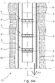
- Figures 6a and 6b show the apparatus 1 according to the present disclosure in an embodiment in which the displacement member 5 is formed by three sets of collar-shaped bodies 5, the sets being spaced apart.
- the collar-shaped bodies 5 are attached to the carrier body 3 by means of a hinging device (not specifically shown).
- the hinging device is of a kind known per se that is arranged to hold the collar-shaped bodies 5 in an unfolded position when the apparatus 1 is being moved in a first direction as shown by means of the arrow F1 in figure 6a , but the collar-shaped bodies 5 collapsing and being moved in towards the carrier body 3 as the apparatus 1 is being moved in a second direction as shown by means of the arrow F2 in figure 6b .
- the arrows in figures 6a and 6b may be placed the other way round, but then the shoulder element 3" shown in figure 6b will have to be placed on an upper side of the attachment portion of the collar-shaped bodies 5, and not the lower side as shown in figure 6b .
- the hinging devices are attached to pipe pieces 3' screwed together between sections of carrier bodies 3.
- the displacement members 5 that are shown in figures 6a and 6b require a driving device 11 that provides a reciprocating motion along the longitudinal axis L of the casing 13.
- a reciprocating driving device may be of a kind known per se and will therefore not be mentioned in any greater detail in this document.
- the apparatus 1 shown in figure 6a may be provided with an attachment portion 7 which is fixed such as for the blades 5 shown in figures 1a and 1b , for example.
- the collar-shaped bodies 5 will then project towards the casing 13 independently of whether the apparatus 1 is moving in the direction F1 or F2.
- F1 or F2 the direction of the apparatus 1
- the carrier body 3 and the casing 13 it is an advantage if the radial extent of the collar-shaped elements 5 is smaller than the internal diameter of the casing 13.
- the collar-shaped bodies 5 may be, with respect to materials and flexibility, of the kind that is described for the blades 5 shown in said figures.
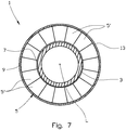
- Figure 7 shows, on a larger scale, a section through the line B-B shown in figure 6a .
- the collar-shaped body 5 is composed of a plurality of collar sector elements 5' (sixteen shown). Even though figure 7 sows said section B-B, figure 7 might equally well have been a section seen from an upper side of a collar-shaped body extending in a helix around the carrier element 3 shown in figure 6a , for example.
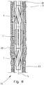
- Figure 8 shows, on a smaller scale, an apparatus 1 according to the disclosure the apparatus being assembled into a stack of several apparatuses 1 with displacement members 5 of different nature.
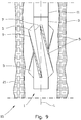
- Figure 9 shows the apparatus of figure 2 shown in an application for positioning a fluidized plugging material in an open-hole section without casing.
- the fluidized plugging material is not shown in figure 9 .
Landscapes
- Engineering & Computer Science (AREA)
- Geology (AREA)
- Life Sciences & Earth Sciences (AREA)
- Mining & Mineral Resources (AREA)
- Geochemistry & Mineralogy (AREA)
- Fluid Mechanics (AREA)
- Environmental & Geological Engineering (AREA)
- General Life Sciences & Earth Sciences (AREA)
- Physics & Mathematics (AREA)
- Mechanical Engineering (AREA)
- Filling Or Emptying Of Bunkers, Hoppers, And Tanks (AREA)
- Fluidized-Bed Combustion And Resonant Combustion (AREA)
- Feeding, Discharge, Calcimining, Fusing, And Gas-Generation Devices (AREA)
- Crucibles And Fluidized-Bed Furnaces (AREA)
- Manufacturing Of Micro-Capsules (AREA)
- Devices And Processes Conducted In The Presence Of Fluids And Solid Particles (AREA)
- Accessories For Mixers (AREA)
- Consolidation Of Soil By Introduction Of Solidifying Substances Into Soil (AREA)
Claims (25)
- Verfahren zum Bereitstellen eines dauerhaften oder vorübergehenden Stopfens in einem Gehäuse (13) in einem Bohrloch (15), wobei der Stopfen mittels eines fluidisierten Stopfmaterials (25) bereitgestellt wird, welches von einer Oberfläche des Bohrlochs (15) in das Bohrloch (15) befördert wird, wobei das Verfahren die Schritte umfasst von:- Verwenden einer Vorrichtung (1) umfassend:- einen Trägerkörper (3), welcher durch einen endlosen Seitenabschnitt, der sich zwischen einem ersten Endabschnitt und einem zweiten Endabschnitt erstreckt, definiert wird;- mindestens ein Verschiebungselement (5), welches auf dem Trägerkörper (3) angeordnet ist, wobei das Verschiebungselement (5) durch eine Oberfläche des Trägerkörpers (3) und eines freien Endabschnitts (9), welcher von der Oberfläche des Trägerkörpers (3) nach aussen weist, definiert ist, wodurch der freie Endabschnitt (9) einer Innenseite des Gehäuses (13) zugewandt ist, wenn er darin angeordnet ist; und- eine Antriebsvorrichtung (11), welche mit dem Trägerkörper (3) verbunden ist, um den Trägerkörper (3) und somit das mindestens eine Verschiebungselement (5) im Gehäuse (13) in Bewegung zu versetzen;- Bewegen der Vorrichtung (1) in das Gehäuse (13) des Bohrlochs (15);- Versetzen der Vorrichtung (1) im Gehäuse (13) in Bewegung und Zuführen des fluidisierten Stopfmaterials (25) von der Oberfläche des Bohrlochs (15), wodurch das fluidisierte Stopfmaterial (25) im Gehäuse (13) in Bewegung versetzt wird;- Weiterbewegen der Vorrichtung (1) während einer vorbestimmten Zeit, nachdem alles Stopfmaterial (25) zugeführt wurde; und- Ziehen der Vorrichtung (1) aus dem Bohrloch (15) heraus.
- Verfahren gemäss Anspruch 1, wobei das Bohrloch (15) ein Ölbohrloch oder ein Gasbohrloch ist.
- Verfahren gemäss Anspruch 1 oder 2, wobei das Gehäuse (13) ein nicht-perforiertes Gehäuse ist.
- Verfahren gemäss Anspruch 1 oder 2, wobei das Gehäuse (13) ein perforiertes Gehäuse mit Perforationen (17) ist, um Fluidkommunikationskanäle zwischen einer inneren Bohrung des Gehäuses (13) und einem Äusseren des Gehäuses (13) bereitzustellen.
- Verfahren gemäss einem der Ansprüche 1 bis 4, wobei die Antriebsvorrichtung (11) ein Rohrstrang ist, welcher angeordnet ist, um um eine Längsachse (L) des Gehäuses (13) herum in Rotation versetzt zu werden, so dass die Bewegung der Vorrichtung (1) eine Drehbewegung um die Längsachse (L) des Gehäuses (13) ist.
- Verfahren gemäss einem der Ansprüche 1 bis 5, wobei das Verschiebungselement (5) eine Klinge (5) ist.
- Verfahren gemäss Anspruch 6, wobei der freie Endabschnitt (9) der Klinge (5) angeordnet ist, um zumindest bei der Drehung des Trägerkörpers (3) eine Ablenkung relativ zu einem zentralen Kontaktabschnitt (7) zwischen der Klinge (5) und dem Trägerkörper (3) aufzuweisen.
- Verfahren gemäss Anspruch 6, wobei der Trägerkörper (3) und die mindestens eine Klinge (5) bei der Drehung bevor die Vorrichtung (1) in das Gehäuse (13) bewegt wurde, einen Kreis mit einem Durchmesser, welcher grösser als ein Innendurchmesser des Gehäuses (13) ist, umschreibt, wodurch die mindestens eine Klinge (5) beim Einsetzen in das Gehäuse (13) eine Krümmung annimmt.
- Verfahren gemäss Anspruch 6, wobei der Trägerkörper (3) und die mindestens eine Klinge (5) bei deren Drehung einen Kreis mit einem Durchmesser umschreibt, welcher gleich wie oder kleiner als ein Innendurchmesser des Gehäuses (13) ist.
- Verfahren gemäss einem der Ansprüche 6 bis 9, wobei sich eine Längsachse der mindestens einen Klinge (5) parallel zu einer Längsachse des Trägerkörpers (3) erstreckt.
- Verfahren gemäss einem der Ansprüche 6 bis 9, wobei sich eine Längsachse der mindestens einen Klinge (5) bezüglich einer Längsachse des Trägerkörpers (3) winklig erstreckt.
- Verfahren gemäss einem der Ansprüche 1 bis 4, wobei die Antriebsvorrichtung (11) ein hin- und herbewegendes Antriebsmittel ist, welches angeordnet ist, um Vorwärts- und Rückwärtsbewegungen (F1, F2) des mindestens einen Verschiebungselements (5) entlang einer Längsachse (L) des Gehäuses (13) bereitzustellen.
- Verfahren gemäss Anspruch 12, wobei das Verschiebungselement (5) ein kragenförmiger Körper ist.
- Verfahren gemäss Anspruch 13, wobei der freie Endabschnitt (9) des kragenförmigen Körpers (5) angeordnet ist, um, zumindest bei Bewegung, eine Ablenkung bezüglich einem zentralen Kontaktabschnitt (7) zwischen dem kragenförmigen Körper (5) und dem Trägerkörper (3) aufzuweisen.
- Verfahren gemäss Anspruch 13 oder 14, wobei sich der kragenförmige Körper (5) in einer Helix um den Trägerkörper (3) herum erstreckt.
- Verfahren gemäss Anspruch 13, 14 oder 15, wobei sich der kragenförmige Körper (5) mindestens um 360° um den Trägerkörper (3) herum erstreckt.
- Verfahren gemäss einem der Ansprüche 13-16, wobei der kragenförmige Körper (5) mindestens zwei Kragensektorelemente (5') beinhaltet.
- Verfahren gemäss Anspruch 17, wobei mindestens einer der Kragensektorelemente (5') mit einem gelenkigen Befestigungsabschnitt versehen ist, so dass sich der freie Endabschnitt (9) während einer der Vorwärts- und Rückwärtsbewegungen (F1, F2) der Vorrichtung (1) im Gehäuse (13) nach innen in Richtung des Trägerkörpers (3) bewegen kann.
- Verfahren gemäss einem der Ansprüche 1-18, wobei das Stopfmaterial (25) ein aushärtbares Material ist.
- Verfahren gemäss Anspruch 19, wobei das aushärtbare Material (25) ein Zementbasiertes Stopfmaterial ist.
- Verfahren gemäss Anspruch 19 oder 20, wobei die Lastkapazität des mindestens einen Verschiebungselements (5) grösser ist als die Lasten, welche das Verschiebungselement (5) bei der Bewegung der Vorrichtung (1) in nicht-ausgehärtetem Stopfmaterial (25) beeinflussen, aber kleiner ist als die Lasten, welche das Verschiebungselement (5) bei der Bewegung der Vorrichtung in ausgehärtetem Stopfmaterial (25) beeinflussen, so dass zumindest ein Bereich des Verschiebungselements (5) abbricht, falls ein Aushärtungsprozess ein vorgegebenes Niveau übersteigt.
- Verfahren gemäss einem der Ansprüche 1 bis 21, wobei ein Abschnitt des Trägerkörpers (3) einen grösseren Aussendurchmesser als ein anderer Abschnitt des Trägerkörpers (3) hat.
- Verfahren gemäss einem der Ansprüche 1 bis 22, wobei das mindestens eine Verschiebungselement (5) zwei oder mehr beabstandete Verschiebungselemente (5) umfasst.
- Verfahren gemäss einem der Ansprüche 1 bis 23, wobei der Trägerkörper (3) mit einer Bohrung versehen ist, welche angeordnet ist, um das Stopfmaterial (25), welches von der Oberfläche des Bohrlochs (15) erhalten wird, durch einen unteren Endabschnitt der Vorrichtung (1) herauszuführen.
- Verfahren gemäss einem der Ansprüche 1 bis 24, wobei mindestens ein Abschnitt des Trägerkörpers (3) aus demselben Material wie das mindestens eine Verschiebungselement (5) gemacht ist.
Applications Claiming Priority (3)
| Application Number | Priority Date | Filing Date | Title |
|---|---|---|---|
| NO20110450 | 2011-03-24 | ||
| NO20120099A NO339005B1 (no) | 2011-03-24 | 2012-01-31 | Apparat og framgangsmåte for anbringelse av et fluidisert pluggmateriale i en brønn |
| PCT/NO2012/050047 WO2012128644A2 (en) | 2011-03-24 | 2012-03-20 | Apparatus and method for positioning of a fluidized plugging material in an oil well or gas well |
Publications (4)
| Publication Number | Publication Date |
|---|---|
| EP2689100A2 EP2689100A2 (de) | 2014-01-29 |
| EP2689100A4 EP2689100A4 (de) | 2015-12-02 |
| EP2689100B1 true EP2689100B1 (de) | 2019-02-06 |
| EP2689100B8 EP2689100B8 (de) | 2019-09-04 |
Family
ID=46879940
Family Applications (1)
| Application Number | Title | Priority Date | Filing Date |
|---|---|---|---|
| EP12760353.8A Active EP2689100B8 (de) | 2011-03-24 | 2012-03-20 | Vorrichtung und verfahren zur positionierung eines fluidisierten stopfmaterials in einem ölbohrloch oder einem gasbohrloch |
Country Status (10)
| Country | Link |
|---|---|
| US (1) | US9416618B2 (de) |
| EP (1) | EP2689100B8 (de) |
| AU (1) | AU2012231912B2 (de) |
| CA (1) | CA2829777C (de) |
| DK (1) | DK2689100T3 (de) |
| EA (1) | EA029357B1 (de) |
| GB (1) | GB2505089B (de) |
| MY (1) | MY170476A (de) |
| NO (1) | NO339005B1 (de) |
| WO (1) | WO2012128644A2 (de) |
Families Citing this family (11)
| Publication number | Priority date | Publication date | Assignee | Title |
|---|---|---|---|---|
| NO339025B1 (no) | 2012-02-03 | 2016-11-07 | Hydra Systems As | Fremgangsmåte ved etablering av en ringromsbarriere i en underjordisk brønn |
| NO335689B1 (no) | 2012-02-17 | 2015-01-19 | Hydra Systems As | Fremgangsmåte ved etablering av en ny brønnbane fra en eksisterende brønn |
| NO339082B1 (no) | 2012-03-09 | 2016-11-14 | Hydra Systems As | Fremgangsmåte for kombinert rengjøring og plugging i en brønn |
| NO337162B1 (no) * | 2013-03-20 | 2016-02-01 | Hydra Panda As | Fremgangsmåte, system og anvendelse for plugging av en brønn |
| NO336038B1 (no) | 2013-08-16 | 2015-04-27 | Hydra Systems As | Fremgangsmåte for etablering av en ny brønnbane fra en eksisterende brønn |
| NO339191B1 (no) * | 2013-09-06 | 2016-11-14 | Hydra Systems As | Fremgangsmåte for isolering av en permeabel sone i en underjordisk brønn |
| NO340959B1 (en) | 2015-06-10 | 2017-07-31 | Hydra Systems As | A method of plugging and abandoning a well |
| GB2543879A (en) * | 2015-07-17 | 2017-05-03 | Conocophillips Co | Well abandonment using vibration to assist cement placement |
| GB2582745B (en) | 2019-03-27 | 2021-09-29 | Ardyne Holdings Ltd | Improvements in or relating to well abandonment |
| NO345955B1 (en) * | 2019-09-23 | 2021-11-15 | Interwell P&A As | A well tool device and method of forming a permanent well barrier, configured to generate a forced flow of molten mass |
| NO346617B1 (en) | 2020-03-09 | 2022-10-31 | Hydra Systems As | A fluid diverter tool, system and method of diverting a fluid flow in a well |
Family Cites Families (19)
| Publication number | Priority date | Publication date | Assignee | Title |
|---|---|---|---|---|
| US1460632A (en) * | 1922-06-28 | 1923-07-03 | Wilson B Wigle | Centering cementing shoe |
| US2402223A (en) * | 1944-06-26 | 1946-06-18 | B And W Inc | Rotary well bore cleaner |
| US2607425A (en) * | 1947-09-26 | 1952-08-19 | Mcgaffey Taylor Corp | Well cementing tool |
| US3260310A (en) * | 1963-05-27 | 1966-07-12 | Brown Oil Tools | Screw-set high-pressure packer |
| US3276521A (en) * | 1963-11-29 | 1966-10-04 | Turbyfill Charles William | Hole conditioner |
| US3351136A (en) * | 1964-09-14 | 1967-11-07 | Nelson Norman A | Casing centralizer and well bore wiper |
| US4088185A (en) * | 1974-12-13 | 1978-05-09 | J. M. Huber Corporation | Molded plastic paraffin scrapers and centralizers |
| US4456064A (en) * | 1983-03-03 | 1984-06-26 | Lamar Ford | Well bore wall cleaner |
| US4595058A (en) * | 1984-08-28 | 1986-06-17 | Shell Oil Company | Turbulence cementing sub |
| US4995456A (en) * | 1990-05-04 | 1991-02-26 | Atlantic Richfield Company | Gravel pack well completions |
| US5657822A (en) | 1995-05-03 | 1997-08-19 | James; Melvyn C. | Drill hole plugging method utilizing layered sodium bentonite and liquid retaining particles |
| AU2744800A (en) * | 1999-01-29 | 2000-08-18 | Schlumberger Technology Corporation | Securing a well casing to a wellbore |
| US6828531B2 (en) * | 2000-03-30 | 2004-12-07 | Homer L. Spencer | Oil and gas well alloy squeezing method and apparatus |
| EP2212514B1 (de) * | 2007-10-03 | 2019-04-10 | M-I Llc | Bohrlochkratzer |
| BRPI0917019A2 (pt) * | 2008-08-15 | 2016-02-16 | Frank S Inr Inc | dispositivo de cimentação e método |
| GB0823194D0 (en) * | 2008-12-19 | 2009-01-28 | Tunget Bruce A | Controlled Circulation work string for well construction |
| US8136594B2 (en) * | 2009-08-24 | 2012-03-20 | Halliburton Energy Services Inc. | Methods and apparatuses for releasing a chemical into a well bore upon command |
| US8443882B2 (en) * | 2010-07-07 | 2013-05-21 | Baker Hughes Incorporated | Wellbore centralizer for tubulars |
| NO335972B1 (no) | 2011-01-12 | 2015-04-07 | Hydra Systems As | Fremgangsmåte for kombinert rengjøring og plugging i en brønn, vaskeverktøy for retningsstyrt spyling i en brønn, samt anvendelse av vaskeverktøyet |
-
2012
- 2012-01-31 NO NO20120099A patent/NO339005B1/no unknown
- 2012-03-20 EA EA201391343A patent/EA029357B1/ru not_active IP Right Cessation
- 2012-03-20 WO PCT/NO2012/050047 patent/WO2012128644A2/en not_active Ceased
- 2012-03-20 AU AU2012231912A patent/AU2012231912B2/en not_active Ceased
- 2012-03-20 CA CA2829777A patent/CA2829777C/en active Active
- 2012-03-20 DK DK12760353.8T patent/DK2689100T3/en active
- 2012-03-20 US US14/003,424 patent/US9416618B2/en not_active Expired - Fee Related
- 2012-03-20 GB GB1316404.1A patent/GB2505089B/en active Active
- 2012-03-20 MY MYPI2013003447A patent/MY170476A/en unknown
- 2012-03-20 EP EP12760353.8A patent/EP2689100B8/de active Active
Non-Patent Citations (1)
| Title |
|---|
| None * |
Also Published As
| Publication number | Publication date |
|---|---|
| GB201316404D0 (en) | 2013-10-30 |
| NO20120099A1 (no) | 2012-09-25 |
| US20150308219A1 (en) | 2015-10-29 |
| WO2012128644A3 (en) | 2013-04-04 |
| GB2505089B (en) | 2015-05-27 |
| EP2689100A2 (de) | 2014-01-29 |
| DK2689100T3 (en) | 2019-04-08 |
| EA201391343A1 (ru) | 2014-03-31 |
| AU2012231912A1 (en) | 2013-11-07 |
| EP2689100B8 (de) | 2019-09-04 |
| GB2505089A (en) | 2014-02-19 |
| US9416618B2 (en) | 2016-08-16 |
| NO339005B1 (no) | 2016-11-07 |
| CA2829777A1 (en) | 2012-09-27 |
| WO2012128644A2 (en) | 2012-09-27 |
| MY170476A (en) | 2019-08-06 |
| AU2012231912B2 (en) | 2015-05-21 |
| EP2689100A4 (de) | 2015-12-02 |
| CA2829777C (en) | 2019-01-22 |
| EA029357B1 (ru) | 2018-03-30 |
Similar Documents
| Publication | Publication Date | Title |
|---|---|---|
| EP2689100B1 (de) | Vorrichtung und verfahren zur positionierung eines fluidisierten stopfmaterials in einem ölbohrloch oder einem gasbohrloch | |
| US9506318B1 (en) | Cementing well bores | |
| EP2823142B1 (de) | Verfahren zum kombinierten reinigen und stopfen eines bohrlochs sowie spülwerkzeug zum spülen in einem bohrloch | |
| EP2976493B1 (de) | Verfahren und system zur abdichtung eines bohrlochs und verwendung von explosiven ladungen beim abdichten von bohrlöchern | |
| EP2758625B1 (de) | Wellenerzeugungsvorrichtung, gehäusesystem und verfahren zur zementierung eines gehäuses in einem bohrloch | |
| CN102482927B (zh) | 用于密封地下钻孔和执行其它线缆井下旋转操作的装置及方法 | |
| EP2956613B1 (de) | Verfahren zum bohrlochschneiden von mindestens einer leitung ausserhalb und entlang eines rohrstranges in einem bohrloch und ohne gleichzeitiges abtrennen des rohrstranges | |
| RU2607832C2 (ru) | Отсоединяющий инструмент | |
| EP2154329A1 (de) | Bewegliche Bohrlochreinigungsvorrichtung | |
| CA2570378A1 (en) | One trip well apparatus with sand control | |
| CN101675212A (zh) | 用于使井眼中的多个产层增产的改进系统和方法 | |
| US9574406B2 (en) | Wellbore completion system with reaming tool | |
| EP3033479B1 (de) | Verfahren zum erstellen eines neuen bohrpfades in einem bestehenden bohrloch | |
| EP3698015B1 (de) | System und verfahren zur reinigung eines ringförmigen bereichs in einem bohrloch | |
| AU2013250913B2 (en) | Wellbore completion system with reaming tool | |
| WO2013101572A2 (en) | Method of fracturing while drilling | |
| US20110198090A1 (en) | Device and Method for Affecting the Flow of Fluid in a Wellbore | |
| RU2366800C2 (ru) | Способ повышения напряженности контакта заколонного цементного камня с окружающей средой в скважине |
Legal Events
| Date | Code | Title | Description |
|---|---|---|---|
| PUAI | Public reference made under article 153(3) epc to a published international application that has entered the european phase |
Free format text: ORIGINAL CODE: 0009012 |
|
| 17P | Request for examination filed |
Effective date: 20130830 |
|
| AK | Designated contracting states |
Kind code of ref document: A2 Designated state(s): AL AT BE BG CH CY CZ DE DK EE ES FI FR GB GR HR HU IE IS IT LI LT LU LV MC MK MT NL NO PL PT RO RS SE SI SK SM TR |
|
| DAX | Request for extension of the european patent (deleted) | ||
| RBV | Designated contracting states (corrected) |
Designated state(s): AL AT BE BG CH CY CZ DE DK EE ES FI FR GB GR HR HU IE IS IT LI LT LU LV MC MK MT NL NO PL PT RO RS SE SI SK SM TR |
|
| A4 | Supplementary search report drawn up and despatched |
Effective date: 20151103 |
|
| RIC1 | Information provided on ipc code assigned before grant |
Ipc: E21B 33/14 20060101ALI20151028BHEP Ipc: E21B 37/02 20060101ALI20151028BHEP Ipc: E21B 43/04 20060101AFI20151028BHEP Ipc: E21B 33/134 20060101ALI20151028BHEP Ipc: E21B 27/02 20060101ALI20151028BHEP |
|
| STAA | Information on the status of an ep patent application or granted ep patent |
Free format text: STATUS: EXAMINATION IS IN PROGRESS |
|
| REG | Reference to a national code |
Ref country code: DE Ref legal event code: R079 Ref document number: 602012056471 Country of ref document: DE Free format text: PREVIOUS MAIN CLASS: E21B0043040000 Ipc: E21B0033130000 |
|
| GRAP | Despatch of communication of intention to grant a patent |
Free format text: ORIGINAL CODE: EPIDOSNIGR1 |
|
| STAA | Information on the status of an ep patent application or granted ep patent |
Free format text: STATUS: GRANT OF PATENT IS INTENDED |
|
| 17Q | First examination report despatched |
Effective date: 20180717 |
|
| RIC1 | Information provided on ipc code assigned before grant |
Ipc: E21B 33/14 20060101ALI20180830BHEP Ipc: E21B 37/02 20060101ALI20180830BHEP Ipc: E21B 33/134 20060101ALI20180830BHEP Ipc: E21B 17/22 20060101ALI20180830BHEP Ipc: E21B 27/02 20060101ALI20180830BHEP Ipc: E21B 33/13 20060101AFI20180830BHEP |
|
| INTG | Intention to grant announced |
Effective date: 20180919 |
|
| GRAS | Grant fee paid |
Free format text: ORIGINAL CODE: EPIDOSNIGR3 |
|
| GRAA | (expected) grant |
Free format text: ORIGINAL CODE: 0009210 |
|
| STAA | Information on the status of an ep patent application or granted ep patent |
Free format text: STATUS: THE PATENT HAS BEEN GRANTED |
|
| AK | Designated contracting states |
Kind code of ref document: B1 Designated state(s): AL AT BE BG CH CY CZ DE DK EE ES FI FR GB GR HR HU IE IS IT LI LT LU LV MC MK MT NL NO PL PT RO RS SE SI SK SM TR |
|
| REG | Reference to a national code |
Ref country code: GB Ref legal event code: FG4D |
|
| REG | Reference to a national code |
Ref country code: CH Ref legal event code: EP Ref country code: AT Ref legal event code: REF Ref document number: 1095028 Country of ref document: AT Kind code of ref document: T Effective date: 20190215 |
|
| REG | Reference to a national code |
Ref country code: IE Ref legal event code: FG4D |
|
| REG | Reference to a national code |
Ref country code: DE Ref legal event code: R096 Ref document number: 602012056471 Country of ref document: DE |
|
| REG | Reference to a national code |
Ref country code: DK Ref legal event code: T3 Effective date: 20190404 |
|
| REG | Reference to a national code |
Ref country code: NL Ref legal event code: FP |
|
| REG | Reference to a national code |
Ref country code: LT Ref legal event code: MG4D |
|
| PG25 | Lapsed in a contracting state [announced via postgrant information from national office to epo] |
Ref country code: PT Free format text: LAPSE BECAUSE OF FAILURE TO SUBMIT A TRANSLATION OF THE DESCRIPTION OR TO PAY THE FEE WITHIN THE PRESCRIBED TIME-LIMIT Effective date: 20190606 Ref country code: LT Free format text: LAPSE BECAUSE OF FAILURE TO SUBMIT A TRANSLATION OF THE DESCRIPTION OR TO PAY THE FEE WITHIN THE PRESCRIBED TIME-LIMIT Effective date: 20190206 Ref country code: NO Free format text: LAPSE BECAUSE OF FAILURE TO SUBMIT A TRANSLATION OF THE DESCRIPTION OR TO PAY THE FEE WITHIN THE PRESCRIBED TIME-LIMIT Effective date: 20190506 Ref country code: SE Free format text: LAPSE BECAUSE OF FAILURE TO SUBMIT A TRANSLATION OF THE DESCRIPTION OR TO PAY THE FEE WITHIN THE PRESCRIBED TIME-LIMIT Effective date: 20190206 Ref country code: FI Free format text: LAPSE BECAUSE OF FAILURE TO SUBMIT A TRANSLATION OF THE DESCRIPTION OR TO PAY THE FEE WITHIN THE PRESCRIBED TIME-LIMIT Effective date: 20190206 |
|
| RBV | Designated contracting states (corrected) |
Designated state(s): AL AT BE BG CH CY CZ DE DK EE ES FI FR GR HR HU IE IS IT LI LT LU LV MC MK MT NL NO PL PT RO RS SE SI SK SM TR |
|
| REG | Reference to a national code |
Ref country code: AT Ref legal event code: MK05 Ref document number: 1095028 Country of ref document: AT Kind code of ref document: T Effective date: 20190206 Ref country code: CH Ref legal event code: PK Free format text: BERICHTIGUNG B8 |
|
| PG25 | Lapsed in a contracting state [announced via postgrant information from national office to epo] |
Ref country code: GR Free format text: LAPSE BECAUSE OF FAILURE TO SUBMIT A TRANSLATION OF THE DESCRIPTION OR TO PAY THE FEE WITHIN THE PRESCRIBED TIME-LIMIT Effective date: 20190507 Ref country code: RS Free format text: LAPSE BECAUSE OF FAILURE TO SUBMIT A TRANSLATION OF THE DESCRIPTION OR TO PAY THE FEE WITHIN THE PRESCRIBED TIME-LIMIT Effective date: 20190206 Ref country code: BG Free format text: LAPSE BECAUSE OF FAILURE TO SUBMIT A TRANSLATION OF THE DESCRIPTION OR TO PAY THE FEE WITHIN THE PRESCRIBED TIME-LIMIT Effective date: 20190506 Ref country code: IS Free format text: LAPSE BECAUSE OF FAILURE TO SUBMIT A TRANSLATION OF THE DESCRIPTION OR TO PAY THE FEE WITHIN THE PRESCRIBED TIME-LIMIT Effective date: 20190606 Ref country code: LV Free format text: LAPSE BECAUSE OF FAILURE TO SUBMIT A TRANSLATION OF THE DESCRIPTION OR TO PAY THE FEE WITHIN THE PRESCRIBED TIME-LIMIT Effective date: 20190206 Ref country code: HR Free format text: LAPSE BECAUSE OF FAILURE TO SUBMIT A TRANSLATION OF THE DESCRIPTION OR TO PAY THE FEE WITHIN THE PRESCRIBED TIME-LIMIT Effective date: 20190206 |
|
| PG25 | Lapsed in a contracting state [announced via postgrant information from national office to epo] |
Ref country code: IT Free format text: LAPSE BECAUSE OF FAILURE TO SUBMIT A TRANSLATION OF THE DESCRIPTION OR TO PAY THE FEE WITHIN THE PRESCRIBED TIME-LIMIT Effective date: 20190206 Ref country code: AL Free format text: LAPSE BECAUSE OF FAILURE TO SUBMIT A TRANSLATION OF THE DESCRIPTION OR TO PAY THE FEE WITHIN THE PRESCRIBED TIME-LIMIT Effective date: 20190206 Ref country code: SK Free format text: LAPSE BECAUSE OF FAILURE TO SUBMIT A TRANSLATION OF THE DESCRIPTION OR TO PAY THE FEE WITHIN THE PRESCRIBED TIME-LIMIT Effective date: 20190206 Ref country code: ES Free format text: LAPSE BECAUSE OF FAILURE TO SUBMIT A TRANSLATION OF THE DESCRIPTION OR TO PAY THE FEE WITHIN THE PRESCRIBED TIME-LIMIT Effective date: 20190206 Ref country code: CZ Free format text: LAPSE BECAUSE OF FAILURE TO SUBMIT A TRANSLATION OF THE DESCRIPTION OR TO PAY THE FEE WITHIN THE PRESCRIBED TIME-LIMIT Effective date: 20190206 Ref country code: EE Free format text: LAPSE BECAUSE OF FAILURE TO SUBMIT A TRANSLATION OF THE DESCRIPTION OR TO PAY THE FEE WITHIN THE PRESCRIBED TIME-LIMIT Effective date: 20190206 Ref country code: RO Free format text: LAPSE BECAUSE OF FAILURE TO SUBMIT A TRANSLATION OF THE DESCRIPTION OR TO PAY THE FEE WITHIN THE PRESCRIBED TIME-LIMIT Effective date: 20190206 |
|
| REG | Reference to a national code |
Ref country code: CH Ref legal event code: PL |
|
| REG | Reference to a national code |
Ref country code: DE Ref legal event code: R097 Ref document number: 602012056471 Country of ref document: DE |
|
| PG25 | Lapsed in a contracting state [announced via postgrant information from national office to epo] |
Ref country code: LU Free format text: LAPSE BECAUSE OF NON-PAYMENT OF DUE FEES Effective date: 20190320 Ref country code: SM Free format text: LAPSE BECAUSE OF FAILURE TO SUBMIT A TRANSLATION OF THE DESCRIPTION OR TO PAY THE FEE WITHIN THE PRESCRIBED TIME-LIMIT Effective date: 20190206 Ref country code: PL Free format text: LAPSE BECAUSE OF FAILURE TO SUBMIT A TRANSLATION OF THE DESCRIPTION OR TO PAY THE FEE WITHIN THE PRESCRIBED TIME-LIMIT Effective date: 20190206 |
|
| REG | Reference to a national code |
Ref country code: BE Ref legal event code: MM Effective date: 20190331 |
|
| PLBE | No opposition filed within time limit |
Free format text: ORIGINAL CODE: 0009261 |
|
| STAA | Information on the status of an ep patent application or granted ep patent |
Free format text: STATUS: NO OPPOSITION FILED WITHIN TIME LIMIT |
|
| PG25 | Lapsed in a contracting state [announced via postgrant information from national office to epo] |
Ref country code: AT Free format text: LAPSE BECAUSE OF FAILURE TO SUBMIT A TRANSLATION OF THE DESCRIPTION OR TO PAY THE FEE WITHIN THE PRESCRIBED TIME-LIMIT Effective date: 20190206 Ref country code: MC Free format text: LAPSE BECAUSE OF FAILURE TO SUBMIT A TRANSLATION OF THE DESCRIPTION OR TO PAY THE FEE WITHIN THE PRESCRIBED TIME-LIMIT Effective date: 20190206 |
|
| 26N | No opposition filed |
Effective date: 20191107 |
|
| PG25 | Lapsed in a contracting state [announced via postgrant information from national office to epo] |
Ref country code: CH Free format text: LAPSE BECAUSE OF NON-PAYMENT OF DUE FEES Effective date: 20190331 Ref country code: LI Free format text: LAPSE BECAUSE OF NON-PAYMENT OF DUE FEES Effective date: 20190331 |
|
| PG25 | Lapsed in a contracting state [announced via postgrant information from national office to epo] |
Ref country code: BE Free format text: LAPSE BECAUSE OF NON-PAYMENT OF DUE FEES Effective date: 20190331 Ref country code: SI Free format text: LAPSE BECAUSE OF FAILURE TO SUBMIT A TRANSLATION OF THE DESCRIPTION OR TO PAY THE FEE WITHIN THE PRESCRIBED TIME-LIMIT Effective date: 20190206 |
|
| PG25 | Lapsed in a contracting state [announced via postgrant information from national office to epo] |
Ref country code: TR Free format text: LAPSE BECAUSE OF FAILURE TO SUBMIT A TRANSLATION OF THE DESCRIPTION OR TO PAY THE FEE WITHIN THE PRESCRIBED TIME-LIMIT Effective date: 20190206 |
|
| PG25 | Lapsed in a contracting state [announced via postgrant information from national office to epo] |
Ref country code: MT Free format text: LAPSE BECAUSE OF NON-PAYMENT OF DUE FEES Effective date: 20190320 |
|
| PG25 | Lapsed in a contracting state [announced via postgrant information from national office to epo] |
Ref country code: CY Free format text: LAPSE BECAUSE OF FAILURE TO SUBMIT A TRANSLATION OF THE DESCRIPTION OR TO PAY THE FEE WITHIN THE PRESCRIBED TIME-LIMIT Effective date: 20190206 |
|
| PG25 | Lapsed in a contracting state [announced via postgrant information from national office to epo] |
Ref country code: HU Free format text: LAPSE BECAUSE OF FAILURE TO SUBMIT A TRANSLATION OF THE DESCRIPTION OR TO PAY THE FEE WITHIN THE PRESCRIBED TIME-LIMIT; INVALID AB INITIO Effective date: 20120320 |
|
| PG25 | Lapsed in a contracting state [announced via postgrant information from national office to epo] |
Ref country code: MK Free format text: LAPSE BECAUSE OF FAILURE TO SUBMIT A TRANSLATION OF THE DESCRIPTION OR TO PAY THE FEE WITHIN THE PRESCRIBED TIME-LIMIT Effective date: 20190206 |
|
| PGFP | Annual fee paid to national office [announced via postgrant information from national office to epo] |
Ref country code: IE Payment date: 20230317 Year of fee payment: 12 Ref country code: FR Payment date: 20230317 Year of fee payment: 12 |
|
| PGFP | Annual fee paid to national office [announced via postgrant information from national office to epo] |
Ref country code: DE Payment date: 20230320 Year of fee payment: 12 |
|
| P01 | Opt-out of the competence of the unified patent court (upc) registered |
Effective date: 20230524 |
|
| REG | Reference to a national code |
Ref country code: DE Ref legal event code: R119 Ref document number: 602012056471 Country of ref document: DE |
|
| PG25 | Lapsed in a contracting state [announced via postgrant information from national office to epo] |
Ref country code: DE Free format text: LAPSE BECAUSE OF NON-PAYMENT OF DUE FEES Effective date: 20241001 |
|
| PG25 | Lapsed in a contracting state [announced via postgrant information from national office to epo] |
Ref country code: FR Free format text: LAPSE BECAUSE OF NON-PAYMENT OF DUE FEES Effective date: 20240331 |
|
| PG25 | Lapsed in a contracting state [announced via postgrant information from national office to epo] |
Ref country code: IE Free format text: LAPSE BECAUSE OF NON-PAYMENT OF DUE FEES Effective date: 20240320 |
|
| PG25 | Lapsed in a contracting state [announced via postgrant information from national office to epo] |
Ref country code: IE Free format text: LAPSE BECAUSE OF NON-PAYMENT OF DUE FEES Effective date: 20240320 Ref country code: FR Free format text: LAPSE BECAUSE OF NON-PAYMENT OF DUE FEES Effective date: 20240331 Ref country code: DE Free format text: LAPSE BECAUSE OF NON-PAYMENT OF DUE FEES Effective date: 20241001 |
|
| PGFP | Annual fee paid to national office [announced via postgrant information from national office to epo] |
Ref country code: DK Payment date: 20260317 Year of fee payment: 15 |
|
| PGFP | Annual fee paid to national office [announced via postgrant information from national office to epo] |
Ref country code: NL Payment date: 20260325 Year of fee payment: 15 |