EP2689241B1 - Vorrichtung zur messung der von einer hautoberfläche durch diffusion abgegebenen menge eines stoffes - Google Patents
Vorrichtung zur messung der von einer hautoberfläche durch diffusion abgegebenen menge eines stoffes Download PDFInfo
- Publication number
- EP2689241B1 EP2689241B1 EP12700812.6A EP12700812A EP2689241B1 EP 2689241 B1 EP2689241 B1 EP 2689241B1 EP 12700812 A EP12700812 A EP 12700812A EP 2689241 B1 EP2689241 B1 EP 2689241B1
- Authority
- EP
- European Patent Office
- Prior art keywords
- measuring
- skin surface
- freedom
- measuring means
- measuring devices
- Prior art date
- Legal status (The legal status is an assumption and is not a legal conclusion. Google has not performed a legal analysis and makes no representation as to the accuracy of the status listed.)
- Not-in-force
Links
- 238000009792 diffusion process Methods 0.000 title claims description 8
- 239000000126 substance Substances 0.000 title claims description 8
- 230000008878 coupling Effects 0.000 claims description 29
- 238000010168 coupling process Methods 0.000 claims description 29
- 238000005859 coupling reaction Methods 0.000 claims description 29
- 239000002775 capsule Substances 0.000 claims description 12
- 238000011156 evaluation Methods 0.000 claims description 8
- 238000005259 measurement Methods 0.000 description 11
- 239000013013 elastic material Substances 0.000 description 3
- 239000004033 plastic Substances 0.000 description 3
- 239000002884 skin cream Substances 0.000 description 2
- 230000036572 transepidermal water loss Effects 0.000 description 2
- 239000000853 adhesive Substances 0.000 description 1
- 230000001070 adhesive effect Effects 0.000 description 1
- 239000000463 material Substances 0.000 description 1
Images



Classifications
-
- G—PHYSICS
- G01—MEASURING; TESTING
- G01N—INVESTIGATING OR ANALYSING MATERIALS BY DETERMINING THEIR CHEMICAL OR PHYSICAL PROPERTIES
- G01N25/00—Investigating or analyzing materials by the use of thermal means
- G01N25/56—Investigating or analyzing materials by the use of thermal means by investigating moisture content
-
- A—HUMAN NECESSITIES
- A61—MEDICAL OR VETERINARY SCIENCE; HYGIENE
- A61B—DIAGNOSIS; SURGERY; IDENTIFICATION
- A61B5/00—Measuring for diagnostic purposes; Identification of persons
- A61B5/42—Detecting, measuring or recording for evaluating the gastrointestinal, the endocrine or the exocrine systems
- A61B5/4261—Evaluating exocrine secretion production
- A61B5/4266—Evaluating exocrine secretion production sweat secretion
-
- G—PHYSICS
- G01—MEASURING; TESTING
- G01K—MEASURING TEMPERATURE; MEASURING QUANTITY OF HEAT; THERMALLY-SENSITIVE ELEMENTS NOT OTHERWISE PROVIDED FOR
- G01K13/00—Thermometers specially adapted for specific purposes
- G01K13/20—Clinical contact thermometers for use with humans or animals
-
- A—HUMAN NECESSITIES
- A61—MEDICAL OR VETERINARY SCIENCE; HYGIENE
- A61B—DIAGNOSIS; SURGERY; IDENTIFICATION
- A61B5/00—Measuring for diagnostic purposes; Identification of persons
- A61B5/68—Arrangements of detecting, measuring or recording means, e.g. sensors, in relation to patient
- A61B5/6801—Arrangements of detecting, measuring or recording means, e.g. sensors, in relation to patient specially adapted to be attached to or worn on the body surface
- A61B5/683—Means for maintaining contact with the body
- A61B5/6831—Straps, bands or harnesses
Definitions
- the invention relates to a device for measuring the amount of a substance released from a skin surface by diffusion.
- Such instruments are from the DE 2553677 known.
- a device for determining the amount of substance emitted by a surface by diffusion has a measuring head.
- This measuring head is an open measuring capsule, in which at least two sensors are arranged, wherein the sensors are arranged at different distances to the skin surface to be examined.
- These instruments are best used to measure transepidermal water loss, the moisture secreted by the skin.
- the measurement with the above-mentioned devices has the disadvantage that the amount of moisture emitted is very low. Therefore, the devices are inaccurate.
- the invention is therefore based on the object to provide a device for measuring the output of a skin surface by diffusion amount of a substance, in which the accuracy of the measurement is increased.
- the measuring head has at least two measuring devices, which are arranged spaced from each other, wherein the total of two measuring devices are movable independently of each other, so that they are when placed on the skin surface can adapt to the curvature of the skin surface, the respective measuring devices each having an open measuring capsule, wherein the measuring capsule has at least two openings, wherein one of the at least two openings on the skin surface to be examined can be placed, wherein provided on a handle at least one coupling device is, and wherein the measuring devices are arranged on this coupling device.
- This has the advantage that the measuring devices for measuring can be placed simultaneously on the skin surface to be examined, even if the skin surface has a curvature, i. that the skin surface is uneven
- the present invention has the advantage that different adjacent areas of the skin section can be examined, wherein the different locations can be treated beforehand, for example with different skin creams, wherein in this measurement, the measured values of the respective measuring devices are output individually. In this way, a measurement can be carried out simultaneously under different conditions at comparable skin sites.
- the device has at least three measuring devices. It can also be provided at least four or at least five measuring devices.
- Each of the at least two measuring devices can each have at least one rotational degree of freedom, so that they are movable independently of one another, wherein all measuring devices can be placed simultaneously on a skin surface having a curvature during measurement.
- Each of the at least two measuring devices can each have at least two rotational degrees of freedom, so that they are movable independently of one another. Also can the at least two measuring devices have three rotational degrees of freedom, so that they are movable independently of each other.
- At least one return element that the measuring devices after measuring, if they are not in contact with the examined Skin surface, return to the original position. This has the advantage that no additional hand is needed to place the measuring head with the at least two measuring devices on the skin.
- the at least two measuring devices can be connected to at least one coupling device.
- the respective measuring devices can each be connected to the device via a coupling device.
- the at least two measuring devices can also be connected to one another via the at least one coupling device.
- the at least one coupling device may at least partially consist of elastic plastic.
- This elastic plastic has the advantage that the measuring devices after measuring, when they are no longer in contact with the skin surface to be examined, return to the starting position.
- the at least one coupling device may have a base element, wherein the at least two measuring devices are connected in an articulated manner to the base element via at least one articulated connection with at least one rotational degree of freedom.
- the at least two measuring devices at least one articulated connection with at least two rotational degrees of freedom can be connected to the basic element in an articulated manner.
- the at least two measuring devices can also be connected in an articulated manner to the basic element via at least one articulated connection with three rotational degrees of freedom.
- the respective articulated connection can have a separate joint per rotational degree of freedom, wherein the joints of a joint connection are coupled together.
- the particular articulation having a certain degree of rotational freedom may comprise a single articulation of the determined rotational degree of freedom.
- a joint with two rotational degrees of freedom is a universal joint
- a joint with three rotational degrees of freedom is, for example, a ball and socket joint.
- a return spring which reset the respective measuring device back to the initial position relative to the base element.
- the distance between the measuring devices can be adjustable. This has the advantage that different skin sites, which have a different distance from each other, can be examined.
- An adjusting arm can be arranged between the respective measuring devices and the base element, so that the distance between the measuring devices is adjustable.
- This adjusting arm can be arranged between the articulated connection and the respective measuring device.
- the adjustment can be arranged between the base member and the hinge connection.
- the adjusting arm may be part of the articulated connection.
- the respective measuring devices can each have an open measuring capsule, wherein the measuring capsule has at least two openings, wherein one of the at least two openings can be placed on the skin surface to be examined.
- At least two sensors can be arranged in the measuring capsule, wherein the sensors are arranged at different distances from the skin surface to be examined during the measurement.
- a device may be provided with a device for measuring the amount of substance which is released from the skin surface by diffusion, the device having an evaluation unit which is connected to the device and receives the measurement results of the measuring device, the evaluation unit having an average measurement value of the individual measuring device calculated and outputs.
- the evaluation unit can individually output the measured values of the individual measuring devices and indicate to which measuring device the respective measuring result belongs.
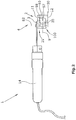
- Fig. 1 shows a first embodiment of the device 1 according to the invention for measuring the release of a skin surface by diffusion amount of a substance.
- the device 1 has a handle 14. On the handle 14, a coupling device 4 is attached. At this coupling device 4 measuring devices 2 are arranged.
- the measuring devices 2 have an open measuring capsule 10, wherein the measuring capsule 10 has at least two openings 11, 12, wherein one of the at least two openings 12 can be placed on the skin surface 30 to be examined.
- the open measuring capsule 10 according to the embodiment of Fig. 1 and 2 has at least two sensors 57, 58, wherein the sensors 57, 58 are arranged at different distances from the skin surface 30 to be examined when measuring, ie when the openings 12 rest on a skin surface 30 to be examined.
- the sensors can measure the temperature and relative humidity of the air. From these values, the transepidermal water loss of the skin can be determined.
- the measurement results of the sensors can be sent to an evaluation unit via electrical lines which run in the interior of the device and are not shown in the figures. Alternatively, however, other measuring devices that can be placed on the skin surface can also be used. These measuring devices need only be able to measure the amount of a substance that is released by diffusion from a skin surface.
- the evaluation unit can calculate and output an average measured value from the measured values of the individual measuring device 2. Alternatively, the evaluation unit can individually output the measured values of the individual measuring device 2 and indicate to which measuring device 2 the respective measuring result belongs.
- FIG. 2 the device is off Fig. 1 shown in the side view. However, for the sake of clarity in Fig. 2 only one measuring device 2 shown.
- the in the FIGS. 1 and 2 Coupling device 4 shown has a base member 3 and hinge joints 21, wherein the measuring devices 2 are each connected via a hinge connection 21 with the base member 3.
- the measuring devices 2 can be pivoted in each case about a first axis 6, 7 or 9 and in each case about a second axis 80, 81 and 82 extending orthogonally to the first axis due to the articulated connections 21 with respect to the base element 3.
- the measuring devices 2 are movable independently of each other, so that they can adapt to the curvature of the skin surface when placed on the skin surface to be examined
- the respective first axes 6, 7 and 9 extend in the illustrated embodiment all in one plane.
- the first axes 6, 7 and 9, about which the respective measuring devices 2 are pivotable, run parallel to the plane in which the respective opening 12 of the measuring devices 2 that can be placed on the skin surface runs.
- the respective axes 80, 81 and 82 are orthogonal to the axes 6, 7 and 9.
- the axes 6, 7 and 9 extend in the horizontal and the axes 80, 81 and 82 in the vertical.
- the articulated connection 21 has an intermediate element 100.
- the basic element 3 is connected via the intermediate element 100 to the corresponding measuring device 2.
- the base element 3 can be pivoted about the axis 82 relative to the intermediate element 100.
- the measuring device 2 can be pivoted about the axis 9 relative to the intermediate element 100.
- the measuring device 2 can be pivoted relative to the base member 3 about the axis 9 and about the axis 82.
- These two pivoting movements can overlap.
- the measuring device 2 can thus be pivoted or moved with respect to two rotational degrees of freedom.
- the measuring device 2 can be thus adapt to a macroscopically uneven surface or to a curvature of a surface.
- the other two measuring devices 2 can be pivoted about the axes 7 and 81 or 6 and 80 in the same way.
- the articulated connections 21 thus have two rotational degrees of freedom, so that the measuring devices 2 can be moved independently of one another in relation to the base element 3 with respect to two rotational degrees of freedom.
- An object may be movable in a space with respect to three degrees of freedom of rotation and three degrees of translational freedom. That the object has three rotational degrees of freedom and three translational degrees of freedom. If an object is movable with respect to three rotational degrees of freedom or has three rotational freedom of straight line, this object can be pivoted about three mutually orthogonal axis, each two of the three axes extend in a plane and the third axis is orthogonal to this plane. If this object is additionally movable with respect to the three translational degrees of freedom or has three translation degrees of freedom, the object can be movable along these three axes. When an object is movable with respect to two rotational degrees of freedom, the object may be movable about two axes that are orthogonal to each other.
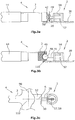
- the hinge joint 21 of the first embodiment may have one rotational degree of freedom or three rotational degrees of freedom. If the hinge 21 has two rotational degrees of freedom, the hinge 21 may also be a universal joint. A universal joint is in Fig. 3 shown.
- the basic element is connected via an intermediate element 42 with the respective measuring device 2.
- the intermediate element 42 has two orthogonally extending shafts, wherein the axes of the shafts are the axes 90 and 40.
- the base element 3 can be pivoted about the axis 40 relative to the intermediate element 42.
- the measuring device 2 can be pivoted about the axis 90 relative to the intermediate element 42.
- the measuring device 2 can be pivoted relative to the base member about the axis 90 and about the axis 40.
- These two Pivoting movements can overlap.
- the measuring device 2 can thus be pivoted or moved with respect to two rotational degrees of freedom.
- the measuring device 2 can thus adapt to the curvature of a surface.
- each of the measuring device 2 has such a universal joint, the measuring devices 2 can be moved independently of each other, so that each of the measuring devices 2 can adapt to the curvature of the skin surface when placed on the skin surface.
- the axis 90 in the embodiment according to Fig. 3a also runs, as well as the axes 6, 7 and 9 of the embodiment FIGS. 1 and 2 in the plane of the opening 12. However, if the axis 90 were located in a measuring device 2 with one of the axes 6, 7 or 9, it would be orthogonal to this axis 6, 7 or 9.
- the axis 40 is orthogonal to the axis 90 and in contrast to the axes 80, 81 and 82 of the embodiment FIGS. 1 and 2 In each position of the measuring device 2, the axis 90 in each case runs orthogonal to the plane in which the opening 12 is arranged.
- the articulated joints 21 may also include a ball joint 110.
- a ball joint has three rotational degrees of freedom.
- the base element 3 has a spherical receiving device 46 for the ball element 48 connected to the respective measuring device 2.
- the measuring device 2 can rotate relative to the base element 3 by three mutually orthogonal axes of rotation, wherein the rotational movements can overlap each other.
- the measuring device 2 can thus move relative to the base element 3 with respect to three rotational degrees of freedom.
- the fact that each of the measuring device 2 has such a ball joint the measuring devices 2 can be moved independently, so that each of the measuring devices 2 can adapt to the curvature of the skin surface when placed on the skin surface, so that the respective opening 12 on the skin surface is placeable.
- a further alternative of a hinge connection 21 is shown.
- the joint 21 according to Fig. 3c has a joint per rotational degree of freedom, these joints coupled together.
- the joints are coupled to each other via the element 52.
- the base member 3 can about the axis 90th of the joint 112 with respect to the element 52 are pivoted.
- the measuring device 2 can be pivoted relative to the element 52 about the axis 6 of the joint 50. Only the axes 6, 90 of the joints 50, 112 are shown.
- the axes 6 and 90 are orthogonal to each other, with both axes 6, 90 parallel to the plane in which the opening 12 extends.
- the Fig. 3c illustrated hinge connection has two rotational degrees of freedom.
- joint connections can also be provided restoring elements, the measuring devices 2 after measuring, when the measuring devices are no longer placed on the skin surface, swing back to a starting position.
- restoring elements for example, return springs can be used. These return springs may for example be torsion springs, which is arranged concentrically to the respective axis.
- the coupling device 4 may consist of an elastic material. Such an embodiment is in Fig. 3d shown.
- the elastic material may be rubber, for example.
- the measuring devices 2 are attached to the elastic coupling device 4.
- the measuring devices 2 can be fastened to the elastic coupling device 4, for example, by means of an adhesive connection. Because the coupling device 4 is designed to be elastic, the measuring devices 2 can move independently of one another and, when placed on a skin surface, can be adapted to the curvature of the skin surface.
- the at least one coupling device 4, so that the measuring devices 2 are adaptable to a curvature of the skin surface have joint connections and additionally elastic elements.
- the elements 20 of the measuring devices 2 are listed elastically.
- the elements 20 may be made of an elastic material such as rubber.
- the measuring device 2 can thus be rotated about the axes already described and in addition they can be movable due to the elastic element 20, so that they are optimally adapted to the curvature of the skin surface when placed on the skin surface.
- the material of the elastic elements 20 can be selected such that the measuring means are adaptable to small curvatures of the skin surface due to the elastic member 20 and due to the joint 21 are adaptable to larger curvatures of the skin surface.
- FIGS. 4a and 4b another embodiment is shown. It differs from the embodiment of the FIGS. 1 and 2 in that adjusting arms 22 are provided.
- the adjusting arms 22 are part of the coupling device 4.
- the adjusting arms 22 can be adjusted relative to the base element 3.
- the adjustment arms 22 can be pivoted about an axis 60, 61, 62, respectively.
- the adjusting arms can be adjusted translationally in relation to the base element 3 along the elongated holes 23, so that the distance of the measuring devices 2 to the base element 3 is adjustable or adjustable. In this way, the distance between the measuring devices 2 can be changed.
- the distance between the measuring devices 2 is thus adjustable or adjustable.
- the adjusting arms 22 are shown in a different position than in Fig. 4a ,
- different skin sections can be examined during a measurement. These different skin sections may be pre-measured e.g. be treated with different skin creams.
- the in the FIGS. 4a and 4b shown measuring devices 2 can be, just as in the FIGS. 1 and 2 described pivot due to the hinge 21 in relation to the respective adjustment arm 22. In this way, the measuring devices 2 can be moved relative to the base element 3 and relative to the respective adjustment arm 22 by two rotational degrees of freedom. In this way, the measuring devices 2 can move independently of each other and adapt flexibly to the curvature of a skin surface.
- joints such as those in the FIGS. 3a-3c shown in the embodiment according to Fig. 4a and 4b can be used.
- a combination of articulated joints and elastic members may be used.
- a joint connection be provided between adjusting 22 and base 3 and the element 20 may be made elastic.
- the adjusting arms 22 can be designed to be elastic.
- FIGS. 5 and 6 another embodiment is shown.
- the measuring devices 2 are arranged at a distance from each other.
- the measuring devices 2 are connected via coupling means 26, 28, 31 with the device.
- the coupling devices 26, 28, 31 are elastic elements, eg elastic plastic elements, such as rubber elements.
- the measuring devices 2 when placed on the skin surface, can be adapted to the curvature of the skin surface or to the uneven skin surface, since the at least two measuring devices 2 are movable independently of one another due to the elastic coupling devices 26, 28, 31. If the measuring devices 2 are not placed on a skin surface, the measuring devices 2 are returned to a starting position, since the coupling devices 26, 28, 31 are elastic. The coupling devices 26, 28, 31 are thus also return elements.
- FIG. 7 a further embodiment is shown, in which the measuring devices 2 are arranged one behind the other.
- one measuring device 2 is connected to another measuring device 2, wherein only the first measuring device 2 is connected to the basic element 3 via the coupling device 32.
- the second measuring device 2 is connected to the first measuring device 2 via the coupling device 34, and the third measuring device 2 is connected to the second measuring device 2 via the coupling device 36.
- coupling means 32,34, 36 are designed to be elastic.
- the coupling means 32, 34, 36 may also be articulated joints. These joints can, for example, have universal joints.
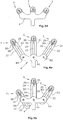
- FIGS. 8 and 9 in each case the measuring devices 2 placed on a skin surface of a device according to the invention are shown.
- the skin surface may be, for example, the skin surface of the skin, arm or face.
- the measuring devices 2 are adapted to the curvature of the skin surface.
- FIGS. 8 and 9 only the measuring devices of the device 2 shown. It is in the FIGS. 8 and 9 illustrated how the measuring devices 2 can adapt to the uneven skin surface.
- the lower opening 12 lies flat on the corresponding skin section to be examined.
Landscapes
- Health & Medical Sciences (AREA)
- Life Sciences & Earth Sciences (AREA)
- Physics & Mathematics (AREA)
- General Health & Medical Sciences (AREA)
- General Physics & Mathematics (AREA)
- Pathology (AREA)
- Physiology (AREA)
- Biomedical Technology (AREA)
- Immunology (AREA)
- Analytical Chemistry (AREA)
- Endocrinology (AREA)
- Gastroenterology & Hepatology (AREA)
- Chemical & Material Sciences (AREA)
- Biophysics (AREA)
- Engineering & Computer Science (AREA)
- Biochemistry (AREA)
- Heart & Thoracic Surgery (AREA)
- Medical Informatics (AREA)
- Molecular Biology (AREA)
- Surgery (AREA)
- Animal Behavior & Ethology (AREA)
- Public Health (AREA)
- Veterinary Medicine (AREA)
- Measurement Of The Respiration, Hearing Ability, Form, And Blood Characteristics Of Living Organisms (AREA)
Description
- Die Erfindung betrifft eine Vorrichtung zur Messung der von einer Hautoberfläche durch Diffusion abgegebenen Menge eines Stoffes.
- Derartige Instrumente sind aus der
DE 2553677 bekannt. Eine solche Vorrichtung zur Bestimmung der von einer Oberfläche durch Diffusion abgegebenen Menge eines Stoffes weist einen Messkopf auf. Dieser Messkopf ist eine offene Messkapsel, in der mindestens zwei Sensoren angeordnet sind, wobei die Sensoren in unterschiedlichen Abständen zu der zu untersuchenden Hautfläche angeordnet sind. Mit diesen Instrumenten lässt sich vorzugsweise der transepidermale Wasserverlust messen, also die Feuchtigkeit, die von der Haut abgesondert wird. - Die Messung mit den oben genannten Geräten hat den Nachteil, dass die Menge der abgegebenen Feuchtigkeit sehr gering ist. Daher sind die Geräte ungenau. Der Erfindung liegt daher die Aufgabe zugrunde, eine Vorrichtung zur Messung des von einer Hautoberfläche durch Diffusion abgegebenen Menge eines Stoffes zu schaffen, bei der die Genauigkeit der Messung erhöht wird.
- Zur Lösung dieser Aufgabe dienen die Merkmale des Anspruchs 1. Die Erfindung sieht in vorteilhafter Weise vor, dass der Messkopf mindestens zwei Messeinrichtungen aufweist, die voneinander beabstandet angeordnet sind, wobei die insgesamt zwei Messeinrichtungen unabhängig voneinander beweglich sind, so dass sie sich beim Aufsetzen auf die Hautoberfläche an die Krümmung der Hautoberfläche anpassen können, wobei die jeweiligen Messeinrichtungen jeweils eine offene Messkapsel aufweisen, wobei die Messkapsel mindestens zwei Öffnungen aufweist, wobei eine der mindestens zwei Öffnungen auf der zu untersuchenden Hautoberfläche plazierbar ist, wobei an einem Griff mindestens eine Kopplungseinrichtung vorgesehen ist, und wobei an dieser Kopplungseinrichtung die Messeinrichtungen angeordnet sind. Dies hat den Vorteil, dass die Messeinrichtungen zum Messen gleichzeitig auf der zu untersuchenden Hautoberfläche platzierbar sind, selbst wenn die Hautoberfläche eine Krümmung aufweist, d.h. dass die Hautoberfläche uneben ist.
- Dies hat ferner den Vorteil, dass die Messung wesentlich genauer ist, da an mehreren vergleichbaren Stellen der Haut gleichzeitig gemessen werden kann und die Messwerte gemittelt werden können. Ferner hat die vorliegende Erfindung den Vorteil, dass unterschiedliche benachbarte Bereiche des Hautabschnitts untersucht werden können, wobei die unterschiedlichen Stellen vorher beispielsweise mit unterschiedlichen Hautcremes behandelt werden können, wobei bei dieser Messung die Messwerte der jeweiligen Messeinrichtungen einzeln ausgegeben werden. Auf diese Weise kann eine Messung gleichzeitig unter unterschiedlichen Bedingungen an vergleichbaren Hautstellen durchgeführt werden.
- Vorzugsweise weist die Vorrichtung mindestens drei Messeinrichtungen auf. Es können auch mindestens vier oder mindestens fünf Messeinrichtungen vorgesehen sein.
- Die jeweils mindestens zwei Messeinrichtungen können jeweils mindestens einen Rotationsfreiheitsgrad aufweisen, so dass sie unabhängig voneinander beweglich sind, wobei beim Messen alle Messeinrichtungen gleichzeitig auf einer eine Krümmung aufweisende Hautoberfläche plazierbar sind. Auch können die jeweils mindestens zwei Messeinrichtungen jeweils mindestens zwei Rotationsfreiheitsgrade aufweise, so dass sie unabhängig voneinander beweglich sind. Auch können die mindestens zwei Messeinrichtungen drei Rotationsfreiheitsgrade aufweisen, so dass sie unabhängig voneinander beweglich sind.
- Es kann mindestens ein Rückstellelement vorgesehen sein, dass die Messeinrichtungen nach dem Messen, wenn sie nicht im Kontakt mit der zu untersuchenden Hautoberfläche sind, wieder in die Ausgangslage zurückstellen. Dies hat den Vorteil, dass keine zusätzliche Hand benötigt wird, um den Messkopf mit den mindestens zwei Messeinrichtungen auf der Haut zu platzieren.
- Die mindestens zwei Messeinrichtungen können mit mindestens einer Kopplungseinrichtung verbunden sein. Die jeweiligen Messeinrichtungen können jeweils über eine Kopplungseinrichtung mit der Vorrichtung verbunden sein. Auch können die mindestens zwei Messeinrichtungen über die mindestens eine Kopplungseinrichtung miteinander verbunden sein.
- Die mindestens eine Kopplungseinrichtung kann zumindest teilweise aus elastischem Kunststoff bestehen. Dieser elastische Kunststoff hat den Vorteil, dass die Messeinrichtungen nach dem Messen, wenn sie nicht mehr in Kontakt mit der zu untersuchenden Hautoberfläche sind, sich wieder in die Ausgangslage zurückstellen.
- Die mindestens eine Kopplungseinrichtung kann ein Grundelement aufweisen, wobei die mindestens zwei Messeinrichtungen über jeweils mindestens eine Gelenkverbindung mit mindestens einem Rotationsfreiheitsgrad mit dem Grundelement gelenkig verbunden sind. Alternativ können die mindestens zwei Messeinrichtungen mindestens eine Gelenkverbindung mit mindestens zwei Rotationsfreiheitsgraden mit dem Grundelement gelenkig verbunden sein. Auch können die mindestens zwei Messeinrichtungen über mindestens eine Gelenkverbindung mit drei Rotationsfreiheitsgraden mit dem Grundelement gelenkig verbunden sein.
- Die jeweilige Gelenkverbindung kann pro Rotationsfreiheitsgrad ein separates Gelenk aufweisen, wobei die Gelenke einer Gelenkverbindung miteinander gekoppelt sind.
- Alternativ kann die jeweilige Gelenkverbindung mit einem bestimmten Rotationsfreiheitsgrad ein einzelnes Gelenk mit dem bestimmten Rotationsfreiheitsgrad aufweisen. Ein Gelenk mit zwei Rotationsfreiheitsgraden ist z.B. ein Kardangelenk und ein Gelenk mit drei Rotationsfreiheitsgraden ist z.B. ein Kugelgelenk.
- Es kann in der jeweiligen Gelenkverbindung pro Freiheitsgrad eine Rückstellfeder vorgesehen sein, die die jeweilige Messeinrichtung wieder in die eine Ausgangslage bezogen auf das Grundelement zurückstellen.
- Der Abstand zwischen den Messeinrichtungen kann einstellbar sein. Dies hat den Vorteil, dass unterschiedliche Hautstellen, die einen unterschiedlichen Abstand voneinander aufweisen, untersucht werden können.
- Zwischen den jeweiligen Messeinrichtungen und dem Grundelement kann ein Verstellarm angeordnet sein, so dass der Abstand zwischen den Messeinrichtungen verstellbar ist.
- Dieser Verstellarm kann zwischen der Gelenkverbindung und der jeweiligen Messeinrichtung angeordnet sein. Alternativ kann der Verstellarm zwischen dem Grundelement und der Gelenkverbindung angeordnet sein. Als weitere Alternative kann der Verstellarm ein Teil der Gelenkverbindung sein.
- Die jeweiligen Messeinrichtungen können jeweils eine offene Messkapsel aufweisen, wobei die Messkapsel mindestens zwei Öffnungen aufweist, wobei eine der mindestens zwei Öffnungen auf der zu untersuchenden Hautoberfläche platzierbar ist.
- In der Messkapsel können mindestens zwei Sensoren angeordnet sein, wobei die Sensoren beim Messen in unterschiedlichen Abständen von der zu untersuchenden Hautoberfläche angeordnet sind.
- Weiter kann ein Gerät mit einer Vorrichtung zur Messung der von der Hautoberfläche durch Diffusion abgebende Menge eines Stoffs vorgesehen sein, wobei das Gerät einer Auswerteeinheit aufweist, die mit der Vorrichtung verbunden ist und die Messergebnisse der Messeinrichtung erhält, wobei die Auswerteeinheit einen Durchschnittsmesswert der einzelnen Messeinrichtung berechnet und ausgibt.
- Alternativ kann die Auswerteeinheit die Messwerte der einzelnen Messeinrichtungen einzeln ausgeben und anzeigen, zu welcher Messeinrichtung das jeweilige Messergebnis gehört.
- Im Folgenden wird unter Bezugnahme auf die Zeichnungen Ausführungsbeispiele der Erfindung näher erläutert.
- Es zeigen schematisch
- Fig. 1
- ein erstes Ausführungsbeispiel in der Draufsicht,
- Fig. 2
- das Ausführungsbeispiel aus
Figur 1 in der Seitenansicht, - Fig. 3a
- ein weiteres Ausführungsbeispiel mit einem Kardangelenk,
- Fig. 3b
- ein weiteres Ausführungsbeispiel mit einem Kugelgelenk,
- Fig. 3c
- ein weiteres Ausführungsbeispiel einer Gelenkverbindung,
- Fig. 3d
- ein weiteres Ausführungsbeispiel mit einem elastischen Element,
- Fig. 4a
- ein weiteres Ausführungsbeispiel mit Verstellarmen,
- Fig. 4b
- das Ausführungsbeispiel aus
Fig. 4a in einer anderen Stellung, - Fig. 5
- ein weiteres Ausführungsbeispiel,
- Fig. 6
- das Ausführungsbeispiel aus
Figur 5 in der Seitenansicht, - Fig. 7
- ein weiteres Ausführungsbeispiel mit hintereinander angeordneten Messeinrichtungen,
- Fig. 8
- die Messeinrichtungen auf einer Hautoberfläche,
- Fig. 9
- die Messeinrichtungen auf einer anderen Hautoberfläche.
-
Fig. 1 zeigt ein erstes Ausführungsbeispiel der erfindungsgemäßen Vorrichtung 1 zur Messung der von einer Hautoberfläche durch Diffusion abgebenden Menge eines Stoffes. - Die Vorrichtung 1 weist einen Griff 14 auf. An dem Griff 14 ist eine Kopplungseinrichtung 4 befestigt. An dieser Kopplungseinrichtung 4 sind Messeinrichtungen 2 angeordnet.
- Die Messeinrichtungen 2 weisen eine offene Messkapsel 10 auf, wobei die Messkapsel 10 mindestens zwei Öffnungen 11, 12 aufweist, wobei eine der mindestens zwei Öffnungen 12 auf der zu untersuchenden Hautoberfläche 30 platzierbar ist. Die offene Messkapsel 10 gemäß dem Ausführungsbeispiel aus
Fig. 1 und2 weist mindestens zwei Sensoren 57, 58 auf, wobei die Sensoren 57, 58 beim Messen, d. h. wenn die Öffnungen 12 auf einer zu untersuchenden Hautoberfläche 30 aufliegen, in unterschiedlichen Abständen von der zu untersuchenden Hautoberfläche 30 angeordnet sind. Die Sensoren können die Temperatur und die relative Feuchtigkeit der Luft messen. Aus diesen Werten kann der transepidermale Wasserverlust der Haut bestimmt werden. Die Messergebnisse der Sensoren können über elektrische Leitungen, die im Inneren der Vorrichtung verlaufen und in den Figuren nicht dargestellt sind, an eine Auswerteeinheit gesendet werden. Alternativ können jedoch auch andere auf der Hautoberfläche plazierbare Messeinrichtungen verwendet werden. Diese Messeinrichtungen müssen lediglich die von einer Hautoberfläche durch Diffusion abgebende Menge eines Stoffes messen können. - Die Auswerteeinheit kann einen Durchschnittsmesswert aus den Messwerten der einzelnen Messeinrichtung 2 berechnen und ausgeben. Alternativ kann die Auswertereinheit die Messwerte der einzelnen Messeinrichtung 2 einzeln ausgeben und anzeigen, zu welcher Messeinrichtung 2 das jeweilige Messergebnis gehört.
- In
Fig. 2 ist die Vorrichtung ausFig. 1 in der Seitenansicht dargestellt. Allerdings ist der Übersichtlichkeit halber inFig. 2 nur eine Messeinrichtung 2 dargestellt. Die in denFign. 1 und2 dargestellte Kopplungseinrichtung 4 weist ein Grundelement 3 und Gelenkverbindungen 21 auf, wobei die Messeinrichtungen 2 jeweils über eine Gelenkverbindung 21 mit dem Grundelement 3 verbunden sind. - Die Messeinrichtungen 2 können aufgrund der Gelenkverbindungen 21 im Bezug zu dem Grundelement 3 jeweils um eine erste Ache 6, 7 bzw. 9 und jeweils um eine orthogonal zu der ersten Achse verlaufenden zweiten Achse 80, 81 und 82 verschwenkt werden. Die Messeinrichtungen 2 können sich, wenn sie jeweils um die Achse 6, 7 und 9 und/oder die Achse 80, 81, 82 verschwenkt werden, unabhängig voneinander bewegen, so dass sie zum Messen gleichzeitig auf einer makroskopisch unebenen Hautoberfläche plazierbar sind. Die Messeinrichtungen 2 sind unabhängig voneinander beweglich, so dass sie sich beim Aufsetzen auf die zu untersuchende Hautoberfläche an die Krümmung der Hautoberfläche anpassen können
- Die jeweils ersten Achsen 6, 7 und 9 verlaufen in dem dargestellten Ausführungsbeispiel alle in einer Ebene. Die ersten Achsen 6, 7 und 9, um die die jeweiligen Messeinrichtungen 2 schwenkbar sind, verlaufen parallel zu der Ebene, in der die jeweilige auf der Hautoberfläche plazierbare Öffnung 12 der Messeinrichtungen 2 verläuft.
- Die jeweiligen Achsen 80, 81 und 82 verlaufen orthogonal zu den Achsen 6, 7 und 9.
- In dem Fall, in dem die Messeinrichtungen 2 auf einer ebenen Oberfläche plaziert sind, verlaufen die Achsen 6, 7 und 9 in der Horizontalen und die Achsen 80, 81 und 82 in der Vertikalen.
- Im Folgenden wird bezogen auf
Fig. 2 eine Gelenkverbindung 21 näher erläutert. Die Gelenkverbindung 21 weist ein Zwischenelement 100 auf. Das Grundelement 3 ist über das Zwischenelement 100 mit der entsprechenden Messeinrichtung 2 verbunden. Das Grundelement 3 kann um die Achse 82 bezogen auf das Zwischenelement 100 verschwenkt werden. Die Messeinrichtung 2 kann um die Achse 9 bezogen auf das Zwischenelement 100 verschwenkt werden. Somit kann die Messeinrichtung 2 bezogen auf das Grundelement 3 um die Achse 9 und um die Achse 82 verschwenkt werden. Diese beiden Schwenkbewegungen können sich überlagern. Die Messeinrichtung 2 kann somit in Bezug auf zwei Rotationsfreiheitsgrade verschwenkt bzw. bewegt werden. Die Messeinrichtung 2 kann sich somit an eine makroskopisch unebene Oberfläche bzw. an eine Krümmung einer Oberfläche anpassen. Die anderen beiden Messeinrichtungen 2 können auf die gleiche Art und Weise um die Achsen 7 und 81 bzw. 6 und 80 verschwenkt werden. - Die Gelenkverbindungen 21 weisen somit zwei Rotationsfreiheitsgrade auf, so dass die Messeinrichtungen 2 im Bezug zu dem Grundelement 3 bezogen auf zwei Rotationsfreiheitsgrad unabhängig voneinander bewegbar sind.
- Ein Objekt kann in einem Raum bezüglich drei Rotationsfreiheitgraden und drei Translationsfreiheitsgraden bewegbar sein. D.h. das Objekt weist drei Rotationsfreiheitsgerade und drei Translationsfreiheitsgerade auf. Wenn ein Objekt bezüglich drei Rotationsfreiheitsgraden bewegbar ist bzw. drei Rotationsfreiheitsgerade aufweist, so kann diese Objekt um drei orthogonal zueinander verlaufende Achse verschwenkt werden, wobei jeweils zwei der drei Achsen in einer Ebene verlaufen und die dritte Achse orthogonal zu dieser Ebene verläuft. Wenn dieses Objekt zusätzlich in Bezug zu den drei Translationsfreiheitsgraden bewegbar ist bzw. drei Translationsfreiheitsgerade aufweist, so kann das Objekt entlang dieser drei Achsen bewegbar sein. Wenn ein Objekt bezüglich zweier Rotationsfreiheitsgrade bewegbar ist, so kann das Objekt um zwei orthogonal zueinander verlaufenden Achsen bewegbar sein.
- Alternativ kann die Gelenkverbindung 21 des ersten Ausführungsbeispiels einen Rotationsfreiheitsgrad bzw. drei Rotationsfreiheitsgrade aufweisen. Wenn die Gelenkverbindung 21 zwei Rotationsfreiheitsgrade aufweist, kann die Gelenkverbindung 21 auch ein Kardangelenk sein. Ein Kardangelenk ist in
Fig. 3 dargestellt. - Bei dem Kardangelenk gemäß
Fig. 3a ist das Grundelement über ein Zwischenelement 42 mit der jeweiligen Messeinrichtung 2 verbunden. Das Zwischenelement 42 weist zwei orthogonal zueinander verlaufende Wellen auf, wobei die Achsen der Wellen die Achsen 90 und 40 sind. Das Grundelement 3 kann um die Achse 40 bezogen auf das Zwischenelement 42 verschwenkt werden. Die Messeinrichtung 2 kann um die Achse 90 bezogen auf das Zwischenelement 42 verschwenkt werden. Somit kann die Messeinrichtung 2 bezogen auf das Grundelement um die Achse 90 und um die Achse 40 verschwenkt werden. Diese beiden Schwenkbewegungen können sich überlagern. Die Messeinrichtung 2 kann somit in Bezug auf zwei Rotationsfreiheitsgrade verschwenkt bzw. bewegt werden. Die Messeinrichtung 2 kann sich somit an die Krümmung einer Oberfläche anpassen. Dadurch, dass jede der Messeinrichtung 2 ein solches Kardangelenk aufweist, können die Messeinrichtungen 2 unabhängig voneinander bewegt werden, so dass sich jede der Messeinrichtungen 2 beim Aufsetzen auf die Hautoberfläche an die Krümmung der Hautoberfläche anpassen kann. Die Achse 90 in dem Ausführungsbeispiel gemäßFig. 3a verläuft ebenfalls, so wie die Achsen 6, 7 und 9 des Ausführungsbeispiels aufFign. 1 und2 , in der Ebene der Öffnung 12. Allerdings verliefe die Achse 90, wenn sie in einer Messeinrichtung 2 mit einer der Achsen 6, 7 oder 9 angeordnet wäre, orthogonal zu dieser Achse 6, 7 oder 9. - Die Achse 40 verläuft orthogonal zu der Achse 90 und im Gegensatz zu den Achsen 80, 81 und 82 des Ausführungsbeispiels auf
Fign. 1 und2 verläuft die Achse 90 in jeder Stellung der Messeinrichtung 2 jeweils orthogonal zu der Ebene, in der die Öffnung 12 angeordnet ist. - Alternativ können die Gelenkverbindungen 21 auch ein Kugelgelenk 110 aufweisen. Ein solches ist in
Fig. 3b dargestellt. Ein Kugelgelenk weist drei Rotationsfreiheisgrade auf. Das Grundelement 3 weist eine kugelförmige Aufnahmeeinrichtung 46 für das mit der jeweiligen Messeinrichtung 2 verbundene Kugelelement 48 auf. Die Messeinrichtung 2 kann bezogen auf das Grundelement 3 um drei orthogonal zueinander verlaufenden Rotationsachsen rotieren, wobei sich die Rotationsbewegungen einander überlagern können. Die Messeinrchtung 2 kann sich somit bezogen auf das Grundelement 3 bezüglich dreier Rotationsfreiheitsgrade bewegen. Dadurch, dass jede der Messeinrichtung 2 ein solches Kugelgelenk aufweist, können die Messeinrichtungen 2 unabhängig voneinander bewegt werden, so dass sich jede der Messeinrichtungen 2 beim Aufsetzen auf die Hautoberfläche an die Krümmung der Hautoberfläche anpassen kann, so dass die jeweilige Öffnung 12 auf der Hautoberfläche plazierbar ist. - In
Fig. 3c ist eine weitere Alternative einer Gelenkverbindung 21 dargestellt. Die Gelenkverbindung 21 gemäßFig. 3c weist pro Rotationsfreiheitsgrad ein Gelenk auf, wobei diese Gelenke miteinander gekoppelt. Die Gelenke sind über das Element 52 miteinander gekoppelt sind. Das Grundelement 3 kann um die Achse 90 des Gelenks 112 bezogen auf das Element 52 verschwenkt werden. Die Messeinrichtung 2 kann bezogen auf das Element 52 um die Achse 6 des Gelenks 50 verschwenkt werden. Es sind lediglich die Achsen 6, 90 der Gelenke 50, 112 dargestellt. Die Achsen 6 und 90 verlaufen orthogonal zueinander, wobei beiden Achsen 6, 90 parallel zu der Ebene verlaufen, in der die Öffnung 12 verläuft. Die inFig. 3c dargestellte Gelenkverbindung weist zwei Rotationsfreiheitsgrade auf. - Bei den in den
Fign. 1-3c dargestellten Gelenkverbindungen können auch Rückstellelemente vorgesehen sein, die die Messeinrichtungen 2 nach dem Messen, wenn die Messeinrichtungen nicht mehr auf der Hautoberfläche plaziert sind, wieder in eine Ausgangslage zurückschwenken. Als Rückstellelemente können beispielsweise Rückstellfedern verwendet werden. Diese Rückstellfedern können beispielsweise Torsionsfedern sein, die konzentrisch zu der jeweiligen Achse angeordnet ist. - Als Alternative zu Gelenkverbindungen kann die Kopplungseinrichtung 4 aus einem elastischen Material bestehen. Ein solches Ausführungsbeispiel ist in
Fig. 3d dargestellt. Das elastische Material kann beispielsweise Gummi sein. Die Messeinrichtungen 2 sind an der elastischen Kopplungseinrichtung 4 befestigt. Die Messeinrichtungen 2 können beispielsweise mittels einer Klebeverbindung an der elastischen Kopplungseinrichtung 4 befestigt sein. Dadurch, dass die Kopplungseinrichtung 4 elastisch ausgeführt ist, können sich die Messeinrichtungen 2 unabhängig voneinander bewegen und beim Aufsetzen auf eine Hautoberfläche an die Krümmung der Hautoberfläche angepasst werden. - Als weitere Alternative kann die mindestens eine Kopplungseinrichtung 4, damit die Messeinrichtungen 2 an eine Krümmung der Hautoberfläche anpassbar sind, Gelenkverbindungen und zusätzlich elastische Elemente aufweisen. So kann beispielsweise bei den in
Fig. 1 bis 3c dargestellten Ausführungsbeispielen jeweils die Elemente 20 der Messeinrichtungen 2 elastisch aufgeführt sein. Die Elemente 20 können aus einem elastischen Material, wie z.B. Gummi, bestehen. Die Messeinrichtung 2 können somit um die bereits beschriebenen Achsen rotiert werden und zusätzlich können sie aufgrund des elastischen Elementes 20 bewegbar sein, so dass sie beim Aufsetzen auf die Hautoberfläche optimal an die Krümmung der Hautoberfläche anpassbar sind. Das Material der elastischen Elemente 20 kann derart gewählt sein, dass die Messeinrichtungen aufgrund des elastischen Elements 20 an kleine Krümmungen der Hautoberfläche anpassbar sind und aufgrund der Gelenkverbindung 21 an größere Krümmungen der Hautoberfläche anpassbar sind. - In
Fign. 4a und 4b ist ein weiteres Ausführungsbeispiel dargestellt. Es unterscheidet sich von dem Ausführungsbeispiel aus denFign. 1 und2 dadurch, dass Verstellarme 22 vorgesehen sind. Die Verstellarme 22 sind Teil der Kopplungseinrichtung 4. Die Verstellarme 22 können bezüglich des Grundelementes 3 verstellt werden. So können die Verstellarme 22 z.B. um jeweils eine Achse 60, 61, 62 verschwenkt werden. Zudem können die Verstellarme translatorisch in Bezug zu dem Grundelement 3 entlang der Langlöcher 23 verstellt werden, so dass der Abstand der Messeinrichtungen 2 zu dem Grundelement 3 verstellbar bzw. einstellbar ist. Auf diese Weise kann auch der Abstand zwischen den Messeinrichtungen 2 verändert werden. Der Abstand zwischen den Messeinrichtungen 2 ist somit einstellbar bzw. verstellbar. InFig. 4b sind die Verstellarme 22 in einer anderen Stellung dargestellt als inFig 4a . - Dadurch, dass der Abstand zwischen dem Messeinrichtungen 2 veränderbar ist, können unterschiedliche Hautabschnitte bei einer Messung untersucht werden. Diese unterschiedlichen Hautabschnitte können vor der Messung z.B. mit unterschiedlichen Hautcremes behandelt werden.
- Die in den
Fign. 4a und 4b dargestellten Messeinrichtungen 2 lassen sich, genauso wie in denFign. 1 und2 beschrieben, aufgrund der Gelenkverbindung 21 in Bezug zu dem jeweiligen Verstellarm 22 verschwenken. Auf diese Weise lassen sich die Messeinrichtungen 2 bezogen auf das Grundelement 3 und bezogen auf den jeweiligen Verstellarm 22 um zwei Rotationsfreiheitsgrade bewegen. Auf diese Weise können sich die Messeinrichtungen 2 unabhängig voneinander bewegen und sich flexibel an die Krümmung einer Hautoberfläche anpassen. - Es versteht sich, dass unterschiedlichen Gelenkverbindungen, z.B. solche wie in den
Fign. 3a-3c dargestellt, in dem Ausführungsbeispiel gemäßFig. 4a und 4b verwendet werden können. Auch kann eine Kombination aus Gelenkverbindungen und elastischen Elementen verwendet werden. So kann z.B. eine Gelenkverbindung zwischen Verstellarm 22 und Grundelement 3 vorgesehen sein und das Element 20 kann elastisch ausgeführt sein. Als weitere Alternative können auch die Verstellarme 22 elastisch ausgeführt sein. - In
Figur 5 und 6 ist ein weiteres Ausführungsbeispiel dargestellt. Die Messeinrichtungen 2 sind beabstandet voneinander angeordnet. Die Messeinrichtungen 2 sind über Kopplungseinrichtungen 26, 28, 31 mit der Vorrichtung verbunden. Die Kopplungseinrichtungen 26, 28, 31 sind elastische Elemente, z.B. elastische Kunststoffelemente, wie z.B. Gummielemente. - Wie in
Figur 6 dargestellt können die Messeinrichtungen 2 beim Aufsetzen auf die Hautoberfläche an die Krümmung der Hautoberfläche bzw. an die unebene Hautoberfläche anpassen, da die mindestens zwei Messeinrichtungen 2 aufgrund der elastischen Kopplungseinrichtungen 26, 28, 31 unabhängig voneinander beweglich sind. Wenn die Messeinrichtungen 2 nicht auf einer Hautoberfläche plaziert sind, werden die Messeinrichtungen 2 wieder in eine Ausgangsposition zurückgestellt, da die Kopplungseinrichtungen 26, 28, 31 elastisch sind. Die Kopplungseinrichtungen 26, 28, 31 sind somit auch Rückstellelemente. - In
Figur 7 ist ein weiteres Ausführungsbeispiel dargestellt, bei dem die Messeinrichtungen 2 hintereinander angeordnet sind. Es ist jeweils eine Messeinrichtung 2 mit einer anderen Messeinrichtung 2 verbunden, wobei nur die erste Messeinrichtung 2 über die Kopplungseinrichtung 32 mit dem Grundelement 3 verbunden ist. Die zweite Messeinrichtung 2 ist über die Kopplungseinrichtung 34 mit der ersten Messeinrichtung 2 verbunden und die dritte Messeinrichtung 2 ist über die Kopplungseinrichtung 36 mit der zweiten Messeinrichtung 2 verbunden. Die inFig. 7 dargestellten Kopplungseinrichtungen 32,34, 36 sind elastisch ausgeführt. Die Kopplungseinrichtungen 32, 34, 36 können jedoch auch Gelenkverbindungen sein. Diese Gelenkverbindungen können z.B. Kardangelenke aufweisen. - In
Figuren 8 und 9 sind jeweils die auf einer Hautoberfläche plazierten Messeinrichtungen 2 einer erfindungsgemäßen Vorrichtung dargestellt. Die Hautoberfläche kann beispielsweise die Hautoberfläche der Haut, des Arms oder des Gesichts sein. Die Messeinrichtungen 2 sind an die Krümmung der Hautoberfläche angepasst. In denFiguren 8 und 9 sind jedoch von der Vorrichtung nur die Messeinrichtungen 2 dargestellt. Es ist in denFiguren 8 und 9 dargestellt, wie die Messeinrichtungen 2 sich an die unebene Hautoberfläche anpassen können. Die untere Öffnung 12 liegt dabei plan auf dem entsprechenden zu untersuchenden Hautabschnitt auf.
Claims (14)
- Vorrichtung (1) zur Messung der von einer Hautoberfläche (30) durch Diffusion abgegebenen Menge eines Stoffes, mit
einem auf der Hautoberfläche (30) plazierbaren Messkopf,
wobei der Messkopf mindestens zwei Messeinrichtungen (2) aufweist, die voneinander beabstandet angeordnet sind, wobei die insgesamt mindestens zwei Messeinrichtungen (2) unabhängig voneinander beweglich sind, so dass sie beim Aufsetzen auf die Hautoberfläche an die Krümmung der Hautoberfläche (30) anpassbar sind, wobei die jeweiligen Messeinrichtungen (2) jeweils eine offene Messkapsel (10) aufweisen, wobei die Messkapsel (10) mindestens zwei Öffnungen (11,12) aufweist, wobei eine der mindestens zwei Öffnungen (12) auf der zu untersuchenden Hautoberfläche (30) plazierbar ist, wobei an einem Griff (14) mindestens eine Kopplungseinrichtung (4) vorgesehen ist, und wobei an dieser Kopplungseinrichtung (4) die Messeinrichtungen (2) angeordnet sind. - Vorrichtung nach Anspruch 1, dadurch gekennzeichnet, dass die jeweils mindestens zwei Messeinrichtungen (2) bezogen auf mindestens einen Rotationsfreiheitsgrad unabhängig voneinander beweglich sind, so dass beim Messen alle Messeinrichtungen (2) gleichzeitig auf einer unebenen Hautoberfläche (30) plazierbar sind.
- Vorrichtung nach Anspruch 1 oder 2, dadurch gekennzeichnet, dass die jeweils mindestens zwei Messeinrichtungen (2) bezogen auf mindestens zwei Rotationsfreiheitsgrade unabhängig voneinander beweglich sind.
- Vorrichtung nach einem der Ansprüche 1 bis 3, dadurch gekennzeichnet, dass die jeweils mindestens zwei Messeinrichtungen (2) bezogen auf drei Rotationsfreiheitsgrade unabhängig voneinander beweglich sind.
- Vorrichtung nach einem der Ansprüche 1 bis 4, dadurch gekennzeichnet, dass mindestens ein Rückstellelement vorgesehen ist, dass die Messeinrichtungen (2) nach dem Messen, wenn sie nicht in Kontakt mit der zu untersuchenden Hautoberfläche (30) sind, wieder in die Ausgangslage zurückstellt.
- Vorrichtung nach Anspruch 1, dadurch gekennzeichnet, dass die Kopplungseinrichtung (4) ein Grundelement (3) aufweist, wobei die mindestens zwei Messeinrichtungen (2) über jeweils mindestens eine Gelenkverbindung (21) mit mindestens zwei Rotationsfreiheitgraden mit dem Grundelement (3) gelenkig verbunden sind.
- Vorrichtung nach Anspruch 6, dadurch gekennzeichnet, dass die mindestens zwei Messeinrichtungen (2) über jeweils mindestens eine Gelenkverbindung (21) mit drei Rotationsfreiheitgraden mit dem Grundelement (3) gelenkig verbunden sind.
- Vorrichtung nach Anspruch 6 oder 7, dadurch gekennzeichnet, dass die jeweilige Gelenkverbindung (21) pro Rotationsfreiheitgrad ein separates Gelenk (50, 112) aufweist, wobei die Gelenke (50, 112) einer Gelenkverbindung (21) miteinander gekoppelt sind.
- Vorrichtung nach Anspruch 6 oder 7, dadurch gekennzeichnet, dass die jeweilige Gelenkverbindung (21) mit einem bestimmten Rotationsfreiheitsgrad ein einzelnes Gelenk mit dem entsprechenden Rotationsfreiheitgrad aufweist.
- Vorrichtung nach einem der Ansprüche 6 bis 9, dadurch gekennzeichnet, dass in der jeweiligen Gelenkverbindung (21) pro Freiheitsgrad eine Rückstellfeder vorgesehen ist, die die jeweiligen Messeinrichtung (2) wieder in eine Ausgangslage bezogen auf das Grundelement zurückstellen.
- Vorrichtung nach einem der Ansprüche 1 bis 10, dadurch gekennzeichnet, dass der Abstand zwischen den Messeinrichtungen (2) einstellbar ist
- Vorrichtung nach Anspruch 1, dadurch gekennzeichnet, dass in der Messkapsel (10) mindestens zwei Sensoren (57, 58) angeordnet sind, wobei die Sensoren (57, 58) beim Messen in unterschiedlichen Abständen von der zu untersuchenden Hautoberfläche angeordnet sind.
- Gerät mit einer Vorrichtung nach einem der Ansprüche 1 bis 12, wobei das Gerät eine Auswerteeinheit aufweist, die mit der Vorrichtung (1) nach einem der Ansprüche 1 bis 12 verbunden ist und die Messergebnisse der Messeinrichtungen (2) erhält, wobei die Auswerteeinheit einen Durchschnittsmesswert aus den Messwerten der einzelnen Messeinrichtungen (2) berechnet und ausgibt.
- Gerät mit einer Vorrichtung nach einem der Ansprüche 1 bis 12, wobei das Gerät eine Auswerteeinheit aufweist, die mit der Vorrichtung (1) nach einem der Ansprüche 1 bis 12 verbunden ist und die Messergebnisse der Messeinrichtungen (2) erhält, wobei die Auswerteeinheit die Messwerte der einzelnen Messeinrichtunen (2) einzeln ausgibt und anzeigt zu welcher Messeinrichtung das jeweilige Messergebnis gehört.
Applications Claiming Priority (2)
| Application Number | Priority Date | Filing Date | Title |
|---|---|---|---|
| DE202011004427U DE202011004427U1 (de) | 2011-03-25 | 2011-03-25 | Vorrichtung zur Messung der von einer Hautoberfläche durch Diffusion abgegebenen Menge eines Stoffes |
| PCT/EP2012/050646 WO2012130488A1 (de) | 2011-03-25 | 2012-01-17 | Vorrichtung zur messung der von einer hautoberfläche durch diffusion abgegebenen menge eines stoffes |
Publications (2)
| Publication Number | Publication Date |
|---|---|
| EP2689241A1 EP2689241A1 (de) | 2014-01-29 |
| EP2689241B1 true EP2689241B1 (de) | 2018-12-26 |
Family
ID=45524530
Family Applications (1)
| Application Number | Title | Priority Date | Filing Date |
|---|---|---|---|
| EP12700812.6A Not-in-force EP2689241B1 (de) | 2011-03-25 | 2012-01-17 | Vorrichtung zur messung der von einer hautoberfläche durch diffusion abgegebenen menge eines stoffes |
Country Status (3)
| Country | Link |
|---|---|
| EP (1) | EP2689241B1 (de) |
| DE (1) | DE202011004427U1 (de) |
| WO (1) | WO2012130488A1 (de) |
Families Citing this family (2)
| Publication number | Priority date | Publication date | Assignee | Title |
|---|---|---|---|---|
| DE202014005525U1 (de) * | 2014-07-08 | 2015-10-09 | Courage + Khazaka Electronic Gmbh | Vorrichtung zur Messung einer durch Diffusion durch ein Probenmaterial abgegebenen Menge eines Stoffes |
| DE102018215145A1 (de) * | 2018-09-06 | 2020-03-12 | Courage + Khazaka Electronic Gmbh | Vorrichtung und Verfahren zur Bestimmung eines Diffusionswiderstandes von technischen und biologischen Membranen |
Citations (1)
| Publication number | Priority date | Publication date | Assignee | Title |
|---|---|---|---|---|
| DE9318928U1 (de) * | 1993-12-08 | 1994-02-24 | Klyscz, Thomas, Dr.med., 72076 Tübingen | Multifunktionaler Stativsondenhalter zur invasiven und non-invasiven Präzisionsdiagnostik und Therapie in der Medizin |
Family Cites Families (5)
| Publication number | Priority date | Publication date | Assignee | Title |
|---|---|---|---|---|
| SE388045B (sv) | 1974-11-28 | 1976-09-20 | Servo Med Ab | Forfarande vid metning av fran en yta genom diffusion avgiven mengd av exv. vatten samt anordning for genomforande av forfarandet |
| US5203327A (en) * | 1988-09-08 | 1993-04-20 | Sudor Partners | Method and apparatus for determination of chemical species in body fluid |
| US5899856A (en) * | 1988-09-08 | 1999-05-04 | Sudormed, Inc. | Dermal patch detecting long-term alcohol consumption and method of use |
| DE4410691A1 (de) * | 1994-03-28 | 1995-10-05 | Pierre Nicolas Dr Med Foss | Gerät zur Analyse und Dokumentation von Hautveränderungen durch Messungen der Impedanzen und Phasenverschiebungen (CEIOS) |
| US20050119537A1 (en) * | 2003-10-08 | 2005-06-02 | Campbell Michael J.E. | Method and apparatus for performing concurrent multiple measurements of relative hydration |
-
2011
- 2011-03-25 DE DE202011004427U patent/DE202011004427U1/de not_active Expired - Lifetime
-
2012
- 2012-01-17 EP EP12700812.6A patent/EP2689241B1/de not_active Not-in-force
- 2012-01-17 WO PCT/EP2012/050646 patent/WO2012130488A1/de not_active Ceased
Patent Citations (1)
| Publication number | Priority date | Publication date | Assignee | Title |
|---|---|---|---|---|
| DE9318928U1 (de) * | 1993-12-08 | 1994-02-24 | Klyscz, Thomas, Dr.med., 72076 Tübingen | Multifunktionaler Stativsondenhalter zur invasiven und non-invasiven Präzisionsdiagnostik und Therapie in der Medizin |
Also Published As
| Publication number | Publication date |
|---|---|
| WO2012130488A1 (de) | 2012-10-04 |
| DE202011004427U1 (de) | 2012-06-26 |
| EP2689241A1 (de) | 2014-01-29 |
Similar Documents
| Publication | Publication Date | Title |
|---|---|---|
| EP1342050B1 (de) | Ermittlung von korrekturparametern einer dreh- schwenkeinheit mit messendem sensor ( koordinatenmessgerät ) über zwei parameterfelder | |
| EP0092541B1 (de) | Vorrichtung zur Diagnostizierung von Störungen des Bewegungssystems des menschlichen Körpers | |
| WO2009130169A1 (de) | Messverfahren für eine gliederarm-koordinatenmessmaschine | |
| DE102004004678A1 (de) | Drehmomentsensor | |
| EP2405813B1 (de) | Messvorrichtung und verfahren zur bestimmung eines oberflächenverlaufs an einem menschen oder tier | |
| EP0501041B1 (de) | Verfahren zur Seilspannungsmessung und Vorrichtung zu seiner Durchführung | |
| DE69609352T2 (de) | Vorrichtung zur untersuchung der viskoelastizität von lebendem gewebe oder kunstgewebe | |
| EP2689241B1 (de) | Vorrichtung zur messung der von einer hautoberfläche durch diffusion abgegebenen menge eines stoffes | |
| WO2019110051A1 (de) | Anordnung für ein messsystem zum messen an einem messobjekt und verfahren zum messen an einem messobjekt mittels eines messsystems | |
| EP1605853A1 (de) | Verfahren und vorrichtung zur bestimmung eines gelenkpunktes von zwei knochen | |
| DE3146237C2 (de) | Diagnostikeinheit für ophthalmologische Untersuchungen | |
| DE19721015C1 (de) | Universeller Tastkopf für Verzahnungsmessungen | |
| DE69006595T2 (de) | Gerät zur überwachung der bewegungskomponenten der wirbelsäule. | |
| DE112017005342T5 (de) | Messvorrichtung und Verfahren zum Messen des Spiels in einem Kugelgelenk | |
| DE60209933T2 (de) | Dynamometer und zugehöriges auswertungsverfahren | |
| WO2020245424A1 (de) | Prüfstand für eine unterschenkel-orthese und verfahren zum testen einer unterschenkel-orthese mittels eines derartigen prüfstandes | |
| DE102011000054A1 (de) | Torsionssensor | |
| DE4216458C2 (de) | Verfahren zur Erfassung der Oberflächenform von Körpern | |
| EP3629845B1 (de) | Messvorrichtung | |
| DE19905493C2 (de) | Meßvorrichtung zur reproduzierbaren Bestimmung der Qualität menschlichen Gewebes | |
| DE102010010296A1 (de) | System zum Aufbau von photogrammetrischen Messanordnungen | |
| DE102016219257B3 (de) | Vorrichtung zur Positionsbestimmung wenigstens eines Raumpunktes eines Körpers innerhalb eines kartesischen Koordinatensystems | |
| EP2210562B1 (de) | Geführte Sonografie | |
| DE102013108152A1 (de) | Computertomografie-Verfahren zur Bestimmung von Merkmalen an einem Messobjekt | |
| DE102020107525B4 (de) | Luftleitvorrichtung eines Kraftfahrzeugs |
Legal Events
| Date | Code | Title | Description |
|---|---|---|---|
| PUAI | Public reference made under article 153(3) epc to a published international application that has entered the european phase |
Free format text: ORIGINAL CODE: 0009012 |
|
| 17P | Request for examination filed |
Effective date: 20130918 |
|
| AK | Designated contracting states |
Kind code of ref document: A1 Designated state(s): AL AT BE BG CH CY CZ DE DK EE ES FI FR GB GR HR HU IE IS IT LI LT LU LV MC MK MT NL NO PL PT RO RS SE SI SK SM TR |
|
| DAX | Request for extension of the european patent (deleted) | ||
| STAA | Information on the status of an ep patent application or granted ep patent |
Free format text: STATUS: EXAMINATION IS IN PROGRESS |
|
| 17Q | First examination report despatched |
Effective date: 20170724 |
|
| GRAP | Despatch of communication of intention to grant a patent |
Free format text: ORIGINAL CODE: EPIDOSNIGR1 |
|
| STAA | Information on the status of an ep patent application or granted ep patent |
Free format text: STATUS: GRANT OF PATENT IS INTENDED |
|
| INTG | Intention to grant announced |
Effective date: 20180718 |
|
| GRAS | Grant fee paid |
Free format text: ORIGINAL CODE: EPIDOSNIGR3 |
|
| GRAA | (expected) grant |
Free format text: ORIGINAL CODE: 0009210 |
|
| STAA | Information on the status of an ep patent application or granted ep patent |
Free format text: STATUS: THE PATENT HAS BEEN GRANTED |
|
| AK | Designated contracting states |
Kind code of ref document: B1 Designated state(s): AL AT BE BG CH CY CZ DE DK EE ES FI FR GB GR HR HU IE IS IT LI LT LU LV MC MK MT NL NO PL PT RO RS SE SI SK SM TR |
|
| REG | Reference to a national code |
Ref country code: GB Ref legal event code: FG4D Free format text: NOT ENGLISH |
|
| REG | Reference to a national code |
Ref country code: CH Ref legal event code: EP |
|
| REG | Reference to a national code |
Ref country code: AT Ref legal event code: REF Ref document number: 1082097 Country of ref document: AT Kind code of ref document: T Effective date: 20190115 |
|
| REG | Reference to a national code |
Ref country code: DE Ref legal event code: R096 Ref document number: 502012014045 Country of ref document: DE |
|
| REG | Reference to a national code |
Ref country code: IE Ref legal event code: FG4D Free format text: LANGUAGE OF EP DOCUMENT: GERMAN |
|
| PG25 | Lapsed in a contracting state [announced via postgrant information from national office to epo] |
Ref country code: BG Free format text: LAPSE BECAUSE OF FAILURE TO SUBMIT A TRANSLATION OF THE DESCRIPTION OR TO PAY THE FEE WITHIN THE PRESCRIBED TIME-LIMIT Effective date: 20190326 Ref country code: LT Free format text: LAPSE BECAUSE OF FAILURE TO SUBMIT A TRANSLATION OF THE DESCRIPTION OR TO PAY THE FEE WITHIN THE PRESCRIBED TIME-LIMIT Effective date: 20181226 Ref country code: FI Free format text: LAPSE BECAUSE OF FAILURE TO SUBMIT A TRANSLATION OF THE DESCRIPTION OR TO PAY THE FEE WITHIN THE PRESCRIBED TIME-LIMIT Effective date: 20181226 Ref country code: HR Free format text: LAPSE BECAUSE OF FAILURE TO SUBMIT A TRANSLATION OF THE DESCRIPTION OR TO PAY THE FEE WITHIN THE PRESCRIBED TIME-LIMIT Effective date: 20181226 Ref country code: LV Free format text: LAPSE BECAUSE OF FAILURE TO SUBMIT A TRANSLATION OF THE DESCRIPTION OR TO PAY THE FEE WITHIN THE PRESCRIBED TIME-LIMIT Effective date: 20181226 Ref country code: NO Free format text: LAPSE BECAUSE OF FAILURE TO SUBMIT A TRANSLATION OF THE DESCRIPTION OR TO PAY THE FEE WITHIN THE PRESCRIBED TIME-LIMIT Effective date: 20190326 |
|
| REG | Reference to a national code |
Ref country code: NL Ref legal event code: MP Effective date: 20181226 |
|
| REG | Reference to a national code |
Ref country code: LT Ref legal event code: MG4D |
|
| PG25 | Lapsed in a contracting state [announced via postgrant information from national office to epo] |
Ref country code: AL Free format text: LAPSE BECAUSE OF FAILURE TO SUBMIT A TRANSLATION OF THE DESCRIPTION OR TO PAY THE FEE WITHIN THE PRESCRIBED TIME-LIMIT Effective date: 20181226 Ref country code: GR Free format text: LAPSE BECAUSE OF FAILURE TO SUBMIT A TRANSLATION OF THE DESCRIPTION OR TO PAY THE FEE WITHIN THE PRESCRIBED TIME-LIMIT Effective date: 20190327 Ref country code: RS Free format text: LAPSE BECAUSE OF FAILURE TO SUBMIT A TRANSLATION OF THE DESCRIPTION OR TO PAY THE FEE WITHIN THE PRESCRIBED TIME-LIMIT Effective date: 20181226 Ref country code: SE Free format text: LAPSE BECAUSE OF FAILURE TO SUBMIT A TRANSLATION OF THE DESCRIPTION OR TO PAY THE FEE WITHIN THE PRESCRIBED TIME-LIMIT Effective date: 20181226 |
|
| PG25 | Lapsed in a contracting state [announced via postgrant information from national office to epo] |
Ref country code: NL Free format text: LAPSE BECAUSE OF FAILURE TO SUBMIT A TRANSLATION OF THE DESCRIPTION OR TO PAY THE FEE WITHIN THE PRESCRIBED TIME-LIMIT Effective date: 20181226 |
|
| PG25 | Lapsed in a contracting state [announced via postgrant information from national office to epo] |
Ref country code: CZ Free format text: LAPSE BECAUSE OF FAILURE TO SUBMIT A TRANSLATION OF THE DESCRIPTION OR TO PAY THE FEE WITHIN THE PRESCRIBED TIME-LIMIT Effective date: 20181226 Ref country code: PT Free format text: LAPSE BECAUSE OF FAILURE TO SUBMIT A TRANSLATION OF THE DESCRIPTION OR TO PAY THE FEE WITHIN THE PRESCRIBED TIME-LIMIT Effective date: 20190426 Ref country code: IT Free format text: LAPSE BECAUSE OF FAILURE TO SUBMIT A TRANSLATION OF THE DESCRIPTION OR TO PAY THE FEE WITHIN THE PRESCRIBED TIME-LIMIT Effective date: 20181226 Ref country code: ES Free format text: LAPSE BECAUSE OF FAILURE TO SUBMIT A TRANSLATION OF THE DESCRIPTION OR TO PAY THE FEE WITHIN THE PRESCRIBED TIME-LIMIT Effective date: 20181226 Ref country code: PL Free format text: LAPSE BECAUSE OF FAILURE TO SUBMIT A TRANSLATION OF THE DESCRIPTION OR TO PAY THE FEE WITHIN THE PRESCRIBED TIME-LIMIT Effective date: 20181226 |
|
| PG25 | Lapsed in a contracting state [announced via postgrant information from national office to epo] |
Ref country code: RO Free format text: LAPSE BECAUSE OF FAILURE TO SUBMIT A TRANSLATION OF THE DESCRIPTION OR TO PAY THE FEE WITHIN THE PRESCRIBED TIME-LIMIT Effective date: 20181226 Ref country code: SK Free format text: LAPSE BECAUSE OF FAILURE TO SUBMIT A TRANSLATION OF THE DESCRIPTION OR TO PAY THE FEE WITHIN THE PRESCRIBED TIME-LIMIT Effective date: 20181226 Ref country code: IS Free format text: LAPSE BECAUSE OF FAILURE TO SUBMIT A TRANSLATION OF THE DESCRIPTION OR TO PAY THE FEE WITHIN THE PRESCRIBED TIME-LIMIT Effective date: 20190426 Ref country code: SM Free format text: LAPSE BECAUSE OF FAILURE TO SUBMIT A TRANSLATION OF THE DESCRIPTION OR TO PAY THE FEE WITHIN THE PRESCRIBED TIME-LIMIT Effective date: 20181226 Ref country code: EE Free format text: LAPSE BECAUSE OF FAILURE TO SUBMIT A TRANSLATION OF THE DESCRIPTION OR TO PAY THE FEE WITHIN THE PRESCRIBED TIME-LIMIT Effective date: 20181226 |
|
| REG | Reference to a national code |
Ref country code: CH Ref legal event code: PL |
|
| REG | Reference to a national code |
Ref country code: DE Ref legal event code: R097 Ref document number: 502012014045 Country of ref document: DE |
|
| PG25 | Lapsed in a contracting state [announced via postgrant information from national office to epo] |
Ref country code: LU Free format text: LAPSE BECAUSE OF NON-PAYMENT OF DUE FEES Effective date: 20190117 |
|
| REG | Reference to a national code |
Ref country code: BE Ref legal event code: MM Effective date: 20190131 |
|
| REG | Reference to a national code |
Ref country code: IE Ref legal event code: MM4A |
|
| PG25 | Lapsed in a contracting state [announced via postgrant information from national office to epo] |
Ref country code: DK Free format text: LAPSE BECAUSE OF FAILURE TO SUBMIT A TRANSLATION OF THE DESCRIPTION OR TO PAY THE FEE WITHIN THE PRESCRIBED TIME-LIMIT Effective date: 20181226 Ref country code: MC Free format text: LAPSE BECAUSE OF FAILURE TO SUBMIT A TRANSLATION OF THE DESCRIPTION OR TO PAY THE FEE WITHIN THE PRESCRIBED TIME-LIMIT Effective date: 20181226 |
|
| PLBE | No opposition filed within time limit |
Free format text: ORIGINAL CODE: 0009261 |
|
| STAA | Information on the status of an ep patent application or granted ep patent |
Free format text: STATUS: NO OPPOSITION FILED WITHIN TIME LIMIT |
|
| GBPC | Gb: european patent ceased through non-payment of renewal fee |
Effective date: 20190326 |
|
| PG25 | Lapsed in a contracting state [announced via postgrant information from national office to epo] |
Ref country code: BE Free format text: LAPSE BECAUSE OF NON-PAYMENT OF DUE FEES Effective date: 20190131 |
|
| 26N | No opposition filed |
Effective date: 20190927 |
|
| PG25 | Lapsed in a contracting state [announced via postgrant information from national office to epo] |
Ref country code: LI Free format text: LAPSE BECAUSE OF NON-PAYMENT OF DUE FEES Effective date: 20190131 Ref country code: CH Free format text: LAPSE BECAUSE OF NON-PAYMENT OF DUE FEES Effective date: 20190131 |
|
| PG25 | Lapsed in a contracting state [announced via postgrant information from national office to epo] |
Ref country code: IE Free format text: LAPSE BECAUSE OF NON-PAYMENT OF DUE FEES Effective date: 20190117 Ref country code: GB Free format text: LAPSE BECAUSE OF NON-PAYMENT OF DUE FEES Effective date: 20190326 |
|
| PG25 | Lapsed in a contracting state [announced via postgrant information from national office to epo] |
Ref country code: FR Free format text: LAPSE BECAUSE OF NON-PAYMENT OF DUE FEES Effective date: 20190226 Ref country code: SI Free format text: LAPSE BECAUSE OF FAILURE TO SUBMIT A TRANSLATION OF THE DESCRIPTION OR TO PAY THE FEE WITHIN THE PRESCRIBED TIME-LIMIT Effective date: 20181226 |
|
| REG | Reference to a national code |
Ref country code: AT Ref legal event code: MM01 Ref document number: 1082097 Country of ref document: AT Kind code of ref document: T Effective date: 20190117 |
|
| PG25 | Lapsed in a contracting state [announced via postgrant information from national office to epo] |
Ref country code: TR Free format text: LAPSE BECAUSE OF FAILURE TO SUBMIT A TRANSLATION OF THE DESCRIPTION OR TO PAY THE FEE WITHIN THE PRESCRIBED TIME-LIMIT Effective date: 20181226 |
|
| PG25 | Lapsed in a contracting state [announced via postgrant information from national office to epo] |
Ref country code: AT Free format text: LAPSE BECAUSE OF NON-PAYMENT OF DUE FEES Effective date: 20190117 |
|
| PG25 | Lapsed in a contracting state [announced via postgrant information from national office to epo] |
Ref country code: MT Free format text: LAPSE BECAUSE OF FAILURE TO SUBMIT A TRANSLATION OF THE DESCRIPTION OR TO PAY THE FEE WITHIN THE PRESCRIBED TIME-LIMIT Effective date: 20181226 |
|
| PG25 | Lapsed in a contracting state [announced via postgrant information from national office to epo] |
Ref country code: CY Free format text: LAPSE BECAUSE OF FAILURE TO SUBMIT A TRANSLATION OF THE DESCRIPTION OR TO PAY THE FEE WITHIN THE PRESCRIBED TIME-LIMIT Effective date: 20181226 |
|
| PGFP | Annual fee paid to national office [announced via postgrant information from national office to epo] |
Ref country code: DE Payment date: 20210201 Year of fee payment: 10 |
|
| PG25 | Lapsed in a contracting state [announced via postgrant information from national office to epo] |
Ref country code: HU Free format text: LAPSE BECAUSE OF FAILURE TO SUBMIT A TRANSLATION OF THE DESCRIPTION OR TO PAY THE FEE WITHIN THE PRESCRIBED TIME-LIMIT; INVALID AB INITIO Effective date: 20120117 |
|
| PG25 | Lapsed in a contracting state [announced via postgrant information from national office to epo] |
Ref country code: MK Free format text: LAPSE BECAUSE OF FAILURE TO SUBMIT A TRANSLATION OF THE DESCRIPTION OR TO PAY THE FEE WITHIN THE PRESCRIBED TIME-LIMIT Effective date: 20181226 |
|
| REG | Reference to a national code |
Ref country code: DE Ref legal event code: R119 Ref document number: 502012014045 Country of ref document: DE |
|
| PG25 | Lapsed in a contracting state [announced via postgrant information from national office to epo] |
Ref country code: DE Free format text: LAPSE BECAUSE OF NON-PAYMENT OF DUE FEES Effective date: 20220802 |