EP2689637B1 - Mehrzonen-lichtsteuerung - Google Patents
Mehrzonen-lichtsteuerung Download PDFInfo
- Publication number
- EP2689637B1 EP2689637B1 EP12712751.2A EP12712751A EP2689637B1 EP 2689637 B1 EP2689637 B1 EP 2689637B1 EP 12712751 A EP12712751 A EP 12712751A EP 2689637 B1 EP2689637 B1 EP 2689637B1
- Authority
- EP
- European Patent Office
- Prior art keywords
- light
- activity
- activity area
- light controller
- lighting system
- Prior art date
- Legal status (The legal status is an assumption and is not a legal conclusion. Google has not performed a legal analysis and makes no representation as to the accuracy of the status listed.)
- Active
Links
Images

Classifications
-
- H—ELECTRICITY
- H05—ELECTRIC TECHNIQUES NOT OTHERWISE PROVIDED FOR
- H05B—ELECTRIC HEATING; ELECTRIC LIGHT SOURCES NOT OTHERWISE PROVIDED FOR; CIRCUIT ARRANGEMENTS FOR ELECTRIC LIGHT SOURCES, IN GENERAL
- H05B47/00—Circuit arrangements for operating light sources in general, i.e. where the type of light source is not relevant
- H05B47/10—Controlling the light source
- H05B47/105—Controlling the light source in response to determined parameters
- H05B47/115—Controlling the light source in response to determined parameters by determining the presence or movement of objects or living beings
- H05B47/125—Controlling the light source in response to determined parameters by determining the presence or movement of objects or living beings by using cameras
-
- H—ELECTRICITY
- H05—ELECTRIC TECHNIQUES NOT OTHERWISE PROVIDED FOR
- H05B—ELECTRIC HEATING; ELECTRIC LIGHT SOURCES NOT OTHERWISE PROVIDED FOR; CIRCUIT ARRANGEMENTS FOR ELECTRIC LIGHT SOURCES, IN GENERAL
- H05B45/00—Circuit arrangements for operating light-emitting diodes [LED]
- H05B45/10—Controlling the intensity of the light
- H05B45/12—Controlling the intensity of the light using optical feedback
-
- H—ELECTRICITY
- H05—ELECTRIC TECHNIQUES NOT OTHERWISE PROVIDED FOR
- H05B—ELECTRIC HEATING; ELECTRIC LIGHT SOURCES NOT OTHERWISE PROVIDED FOR; CIRCUIT ARRANGEMENTS FOR ELECTRIC LIGHT SOURCES, IN GENERAL
- H05B47/00—Circuit arrangements for operating light sources in general, i.e. where the type of light source is not relevant
- H05B47/10—Controlling the light source
- H05B47/105—Controlling the light source in response to determined parameters
- H05B47/115—Controlling the light source in response to determined parameters by determining the presence or movement of objects or living beings
- H05B47/13—Controlling the light source in response to determined parameters by determining the presence or movement of objects or living beings by using passive infrared detectors
-
- H—ELECTRICITY
- H05—ELECTRIC TECHNIQUES NOT OTHERWISE PROVIDED FOR
- H05B—ELECTRIC HEATING; ELECTRIC LIGHT SOURCES NOT OTHERWISE PROVIDED FOR; CIRCUIT ARRANGEMENTS FOR ELECTRIC LIGHT SOURCES, IN GENERAL
- H05B47/00—Circuit arrangements for operating light sources in general, i.e. where the type of light source is not relevant
- H05B47/10—Controlling the light source
- H05B47/175—Controlling the light source by remote control
- H05B47/198—Grouping of control procedures or address assignation to light sources
- H05B47/1985—Creation of lighting zones or scenes
-
- H—ELECTRICITY
- H05—ELECTRIC TECHNIQUES NOT OTHERWISE PROVIDED FOR
- H05B—ELECTRIC HEATING; ELECTRIC LIGHT SOURCES NOT OTHERWISE PROVIDED FOR; CIRCUIT ARRANGEMENTS FOR ELECTRIC LIGHT SOURCES, IN GENERAL
- H05B47/00—Circuit arrangements for operating light sources in general, i.e. where the type of light source is not relevant
- H05B47/10—Controlling the light source
- H05B47/175—Controlling the light source by remote control
- H05B47/19—Controlling the light source by remote control via wireless transmission
-
- Y—GENERAL TAGGING OF NEW TECHNOLOGICAL DEVELOPMENTS; GENERAL TAGGING OF CROSS-SECTIONAL TECHNOLOGIES SPANNING OVER SEVERAL SECTIONS OF THE IPC; TECHNICAL SUBJECTS COVERED BY FORMER USPC CROSS-REFERENCE ART COLLECTIONS [XRACs] AND DIGESTS
- Y02—TECHNOLOGIES OR APPLICATIONS FOR MITIGATION OR ADAPTATION AGAINST CLIMATE CHANGE
- Y02B—CLIMATE CHANGE MITIGATION TECHNOLOGIES RELATED TO BUILDINGS, e.g. HOUSING, HOUSE APPLIANCES OR RELATED END-USER APPLICATIONS
- Y02B20/00—Energy efficient lighting technologies, e.g. halogen lamps or gas discharge lamps
- Y02B20/40—Control techniques providing energy savings, e.g. smart controller or presence detection
Definitions
- the present invention relates to a light controller for a lighting system, specifically in relation to a lighting system being configured to adaptively control where and during what time periods the lighting system emit light within an activity area, such as an office space.
- the invention also relates to a corresponding method for controlling a lighting system.
- LEDs light emitting diodes
- LEDs have become sufficiently bright and inexpensive, to serve as a light source in for example illumination arrangements such as lamps with adjustable color.
- illumination arrangements such as lamps with adjustable color.
- An adjustable color lighting system is typically constructed by using a number of primary colors, and in one example, the three primaries red, green and blue are used. The color of the generated light is determined by the LEDs that are used, as well as by the mixing ratios. To generate "white", all three LEDs have to be turned on.
- LEDs By using LEDs it is possible to decrease the energy consumption, a requirement, which is well in line with the current environmental trend.
- For further decreasing the energy consumption of the illumination arrangement it is possible to include light sensors and presence detectors, which will detect changes in ambient lighting and approaching persons, respectively. Such additions may in turn lead to a decrease in the time the illumination arrangement is active, as well as an intensity decrease by taking into account the ambient lighting.
- US 2009/0310348 A1 at least in some sense decrease the energy consumption of the lighting system, in this case by making use of detection of people in the space, it may be desirable to provide further enhancements to be able to even further decrease the energy consumption within the space.
- an objective is at least partly met by a light controller configured to control a lighting system for emitting light, comprising an image sensor configured to capture an image of an activity area, and a control unit configured to receive the image, to detect movement within the activity area, and to provide an activation signal for switching on a light source of the lighting system, wherein the control unit is further configured to provide a deactivation signal for switching off the light source after a computed time period if no movement is detected within the activity area, the computed time period being based on a computed distance between a predetermined position within the activity area and a position of the latest detected movement within the activity area.
- the invention it is possible to optimize the "on time” of the light source of the lighting system by computing where within the activity area motion is detected. This has the advantage that it is possible to further decrease the energy consumption of the lighting system as the time the light source of the lighting system is kept on can be minimized because the light controller "knows" where within the activity area motion is present.
- the computed time period is increased if the computed distance between the predetermined position within the activity area and the position of the latest detected movement within the activity area decreases.
- a person approaches the predetermined position within the activity area, which for example may be the centre of the activity area, the time it takes before the light is turned on is increased.
- the person sits down at his desk which preferably may be at the predefined position within the activity area, it will take a long time before it is necessary to again detect any motion before the light is turned off.
- the person is leaving the room, and thus moves away from the predetermined position, the further the person moves away from the predetermined position the shorter it takes before the light is turned off.
- the computed distance between the predetermined position within the activity area and the position of the latest detected movement within the activity area may comprise a distribution of distances. This may accordingly make it possible to provide "fuzzy" activity areas not necessary being completely round or squared, but rather being optimized for the e.g. office space where the light controller is used. Also, this makes it possible to define portions of the activity area having different rules for computing the time period before the light is turned off.
- the light controller further comprises a passive infrared sensor (for example integrated in a PIR-based motion detector) connected to the control unit.
- a passive infrared sensor for example integrated in a PIR-based motion detector
- the light controller may be made very energy efficient as the image sensor is only activated when the passive infrared sensor detects an actual motion within the activity area.
- the passive infrared sensor generally only provides a "digital on/off signal" when motion is detected, whereas the motion sensor may provide a more detailed view (e.g. pixilated) of the activity area.
- the activity area comprises a plurality of individual activity zones each having a predetermined position therein.
- motion in each of the individual activity zones may be detected and used for controlling a possible plurality of light sources for each of the individual activity zones.
- This accordingly provides for the possibility to use a single light controller for controlling a light within a space, such as an office area, where a plurality of persons are moving around and working separate from each other in individual activity zones.
- the plurality of individual activity zones and a corresponding set of rules for determining a computed time period for each of the plurality of individual activity zones are defined during a learning period.
- each of the predefined positions within each of the individual activity zones may be determined by switching on/off the lights within that zone.
- the activity during a predetermined time period e.g. 10 seconds
- the light controller may be provided as a separate unit, but may also be incorporated in with a light source of the lighting system or included in a socket of a light source.
- the light source is preferably selected from a group comprising light emitting diodes (LEDs), organic light emitting diodes (OLEDs), polymeric light emitting diodes (PLEDs), inorganic LEDs, cold cathode fluorescent lamps (CCFLs), hot cathode fluorescent lamps (HCFLs), plasma lamps.
- LEDs have much higher energy efficiency in comparison to conventional light bulbs which generally deliver at best about 6% of their electric power used in the form of light.
- the light source may for example comprise a combination of at least some of red, green, blue, yellow, magenta and cyan LEDs for creating mixed color lighting. It is however also possible to use one or a plurality of white LEDs. Further combinations are also possible.
- a method for controlling a lighting system using a light controller comprising an image sensor and a control unit, the method comprising the steps of capturing an image of an activity area, detecting movement within the activity area, providing an activation signal for switching on a light source of the lighting system, computing a distance between a predetermined position within the activity area and a position of the latest detected movement within the activity area, and providing a deactivation signal for switching off the light source after a computed time period if no movement is detected within the activity area, the computed time period being based on the computed distance.
- the light controller may further comprise a passive infrared sensor. Accordingly, it is also here possible to capture the image only if the passive infrared sensor detects a change in a measured infrared light radiating.
- the lighting system 100 comprises a light controller 102 arranged f.i. in the ceiling of an office space comprising a plurality of desks and arranged to be used by a plurality of persons.
- the lighting system 100 further comprises a plurality of light sources 104, 106, 108 and 110 also arranged in the ceiling of the office space and each arranged to provide a suitable amount of ambient/task illumination within a respective individual activity zone 112, 114, 116 and 118. That is, in the illustrated embodiment a single individual activity zone has a dedicated light source for providing illumination therein.
- Other implementations are of course possible and within the scope of the invention, such as multiple light sources associated with a single activity zone or a light source associated with two activity zones.
- the light sources 104, 106, 108 and 110 may for example be selected from a group comprising light emitting diodes (LEDs), organic light emitting diodes (OLEDs), polymeric light emitting diodes (PLEDs), inorganic LEDs.
- LEDs light emitting diodes
- OLEDs organic light emitting diodes
- PLEDs polymeric light emitting diodes
- inorganic LEDs For emission of white light, a white light emitting LED may be used, as well as a plurality of differently colored LEDs together producing white light, or for example a phosphor coated blue LED producing essentially white light.
- the light controller 102 comprises a control unit 200 connected to an image sensor 202, for example in the form of a low resolution (e.g. VGA) CMOS sensor.
- the light controller 102 further comprises a PIR-based motion detector 204, including a passive infrared sensor, as well as communication circuitry 206 for allowing communication with and control of the light sources 104, 106, 108 and 110.
- the communication circuitry 206 may for example be connected to wired 208 and/or wireless 210 (e.g. an antenna) communication means e.g. allowing communication using standard light control communication standards such as DALI, DMX, ACM, etc.
- the control unit 200 may include a microprocessor, microcontroller, programmable digital signal processor or another programmable device.
- the control unit 200 may also, or instead, include an application specific integrated circuit, a programmable gate array programmable array logic, a programmable logic device, or a digital signal processor.
- the processor may further include computer executable code that controls operation of the programmable device.
- the light controller 102 may be battery powered (not shown) for allowing flexible positioning within the space.
- the light controller 102 may of course be powered using the wired 208 communication means.
- Other configurations are of course possible and within the scope of the invention.
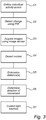
- the light controller 102 is initially, S1, arranged in a "learning phase" where the respective individual activity zone 112, 114, 116 and 118 within the activity area, e.g. the office space, are defined. This may for example be done by acquiring a plurality of images using the image sensor 202, from which the local activity in the office space is detected by means of a motion detection algorithm. As an example, it would be possible to allow for the control unit 200 to store the last acquired image and then subtracts it from the next acquired image in order to get an "activity map" for the office space.
- the activity map may then be binarized using a locally adaptive threshold in order to reduce the dependence on the change of illumination in the office space and due to possible noise from the image sensor 202. After that the activity map may be down-scaled to a suitable resolution (e.g. 32x32 pixels) in order to reduce further computation complexity.
- a suitable resolution e.g. 32x32 pixels
- the activity map for the whole office space does in this case not contain any zone-specific information. Rather, zone-specific activity may be extracted from the activity map by means of zone specific activity masks for each of the individual activity zones 112, 114, 116 and 118 and possible predefined positions within each of the individual activity zones 112, 114, 116 and 118, for example being the center of each of the individual activity zones 112, 114, 116 and 118. Since the light in the individual activity zones 112, 114, 116 and 118 provided by means of the respective light sources 104, 106, 108 and 110, the sensitivity mask preferably covers the individual zone and the possible paths(s) to the entrance(s) of the office space.
- the learning phase, S1 which as above may be automatic, of course possibly also could involve some user interaction, thus allowing it to become manual and/or semi-manual using for example a remote control (not shown).
- the remote control may thus be connected to the control unit 200, advantageously by means of a wireless connection, even though for example a wall mounted user interface is possible having wired connections to the control unit 200.
- the individual activity zones 112, 114, 116 and 118 may also be pre-programmed for a specific room geometry.
- the light controller 102 moves into a control phase where the light provided within each of the individual activity zone 112, 114, 116 and 118 is controlled. Accordingly, in a step S2 the PIR-based motion detector 204 detects a change in a measured infrared light radiating within the office space. Since the PIR-based motion detector 204 is inherently insensitive to changing light conditions and shadow casting from outside of the office space, e.g. through a possible window of the office space, it can robustly detect the presence of persons in the office space. However the PIR-based motion detector 204 can hardly resolve the person's location within the office space and therefore is used for activating the image sensor 202. The later can be used for resolving the occupancy of the individual activity zones 112, 114, 116 and 118 in the office space.
- the image sensor 202 is arranged to acquire, step S3, a plurality of images of the office space, downscaling the images and performing a motion detection to detect where, step S4, within the office space motion is detected. Thereafter, step S5, the control unit 200 computes a distance between the predefined position within each of the individual activity zones 112, 114, 116 and 118 and the position where in the office space motion was detected.
- the distance may comprise a distribution of distances and may also be filtered using e.g. a time based averaging filter for handling fluctuations in changing detected distances.
- step S6 By also computing a change in the distance between the predefined position within the individual activity zone(s) 112, 114, 116 and 118 and where motion is detected it may be possible to determine a movement direction, step S6, i.e. if a person is moving towards or away from the predefined position. Using that information it is possible to adaptively control, step S7, the light sources 104, 106, 108 and 110 to adjust the time the light is turned on within (each of) the specific individual activity zone(s) 112, 114, 116 and 118.
- the "stay on time" determining the duration the light source(s) 104, 106, 108 and 110 are turned on when no motion is detected is reduced when the person is leaving (moving away from) the predefined position and increased when the person approaches the predefined position. Accordingly, it is possible to increase the efficiency of the lighting system 100 as the time between the moment a person leaves the office space and the moment the light is turned off can be kept to a minimum. Conversely, when a person stays close or at the predefined position the stay-on-time is kept long for providing robustness to the lighting system 100 as the light will essentially not be turned off by mistake. It should of course be noted that when motion is again detected the stay-on-time, if the light already is turned on, will again be set to an appropriate value based on where the motion is again detected.
- each of the individual activity zone 112, 114, 116 and 118 it is possible to allow the determination of the computed distances within each of the individual activity zone 112, 114, 116 and 118 to relate to each other for allowing further robustness of the lighting system. For example, if one of the individual activity zones 112 is close to an entrance of the office space, specific rules may apply taking into account which states the light sources 106, 108 and 110 of the other individual activity zones 114, 116 and 118 are in. Also, detected motion "moving" from one of the individual activity zones 112, 114, 116 and 118 towards another of the individual activity zones 112, 114, 116 and 118 may be used for controlling the stay on time within each of the two zones where the motion is detected.
- the present invention relates to a light controller (102) configured to control a lighting system (100) for emitting light, comprising an image sensor (202) configured to capture an image of an activity area, and a control unit (200) configured to received the image, to detecting movement within the activity area , and to provide an activation signal for switching on a light source (104, 106, 108, 110) of the lighting system (100), wherein the control unit (200) is further configured to provide a deactivation signal for switching off the light source (104, 106, 108, 110) after a computed time period if no movement is detected within the activity area , the computed time period being based on a computed distance between a predetermined position within the activity area and a position of the latest detected movement within the activity area.
- the present invention provides advantages in relation to e.g. optimized "on time" of the light source of the lighting system thereby providing an improvement in relation to the total energy consumption of the lighting system.
Landscapes
- Circuit Arrangement For Electric Light Sources In General (AREA)
Claims (11)
- Lichtsteuerung (102), die ausgelegt ist, ein Beleuchtungssystem (100) zum Ausstrahlen von Licht zu steuern, umfassend:einen Bildsensor (202), der ausgelegt ist, ein Bild eines Aktivitätsbereichs zu erfassen; undeine Steuereinheit (200), die ausgelegt ist, das Bild zu empfangen, eine Bewegung innerhalb des Aktivitätsbereichs zu detektieren und ein Aktivierungssignal zum Einschalten einer Lichtquelle (104, 106, 108, 110) des Beleuchtungssystems (100) bereitzustellen,wobei die Steuereinheit (200) weiter ausgelegt ist, ein Deaktivierungssignal zum Ausschalten der Lichtquelle (104, 106, 108, 110) nach einer berechneten Zeitspanne bereitzustellen, wenn keine Bewegung innerhalb des Aktivitätsbereichs detektiert wird, wobei die berechnete Zeitspanne auf einem berechneten Abstand zwischen einer vorbestimmten Position innerhalb des Aktivitätsbereichs und einer Position der zuletzt detektierten Bewegung innerhalb des Aktivitätsbereichs beruht.
- Lichtsteuerung (102) nach Anspruch 1, wobei der berechnete Abstand zwischen der vorbestimmten Position innerhalb des Aktivitätsbereichs und der Position der zuletzt detektierten Bewegung innerhalb des Aktivitätsbereichs eine Verteilung von Abständen umfasst.
- Lichtsteuerung (102) nach Anspruch 1 oder 2, wobei die berechnete Zeitspanne verlängert wird, wenn der berechnete Abstand zwischen der vorbestimmten Position innerhalb des Aktivitätsbereichs und der Position der zuletzt detektierten Bewegung innerhalb des Aktivitätsbereichs abnimmt.
- Lichtsteuerung (102) nach einem der vorstehenden Ansprüche, weiter umfassend einen passiven Infrarotsensor (204), der mit der Steuereinheit (200) verbunden ist, wobei der Bildsensor (202) ausgelegt ist, das Bild zu erfassen, wenn der passive Infrarotsensor (204), eine Änderung in einer gemessenen Infrarotlichtstrahlung detektiert.
- Lichtsteuerung (102) nach einem der vorstehenden Ansprüche, wobei der Aktivitätsbereich eine Vielzahl einzelner Aktivitätszonen (112, 114, 116, 118) umfasst, von welchen jede eine vorbestimmte Position darin hat.
- Lichtsteuerung (102) nach Anspruch 5, die weiter ausgelegt ist, eine Vielzahl einzelner Lichtquellen (104, 106, 108, 110) des Beleuchtungssystems (100) zu steuern, die ausgelegt sind, Licht innerhalb jeder der einzelnen Aktivitätszonen (112, 114, 116, 118) auszustrahlen.
- Lichtsteuerung (102) nach Anspruch 5 oder 6, wobei die Vielzahl einzelner Aktivitätszonen (112, 114, 116, 118) und ein entsprechender Satz von Regeln zum Bestimmen einer berechneten Zeitspanne für jede der Vielzahl einzelner Aktivitätszonen (112, 114, 116, 118) während einer Lernperiode definiert werden.
- Lichtsteuerung (102) nach einem der vorstehenden Ansprüche, wobei die Steuereinheit (200) weiter ausgelegt ist, die vorbestimmte Position innerhalb jeder der Vielzahl einzelner Aktivitätszonen (112, 114, 116, 118) durch Bestimmen einer Änderung in einer Beleuchtung bereitzustellen, wenn die Lichtquellen (104, 106, 108, 110) aktiviert und deaktiviert werden.
- Beleuchtungssystem (100), umfassend eine Lichtsteuerung (102) nach einem der Ansprüche 1-8.
- Verfahren zum Steuern eines Beleuchtungssystems (100), das eine Lichtsteuerung (102) verwendet, wobei die Lichtsteuerung (102) einen Bildsensor (202) und eine Steuereinheit (200) umfasst, das Verfahren umfassend die folgenden Schritte:Erfassen eines Bildes eines Aktivitätsbereichs;Detektieren einer Bewegung innerhalb des Aktivitätsbereichs;Bereitstellen eines Aktivierungssignals zum Einschalten einer Lichtquelle (104, 106, 108, 110) des Beleuchtungssystems (100);Berechnen eines Abstands zwischen einer vorbestimmten Position innerhalb des Aktivitätsbereichs und einer Position der zuletzt detektierten Bewegung innerhalb des Aktivitätsbereichs; undBereitstellen eines Deaktivierungssignals zum Ausschalten der Lichtquelle (104, 106, 108, 110) nach einer berechneten Zeitspanne, wenn keine Bewegung innerhalb des Aktivitätsbereichs detektiert wird, wobei die berechnete Zeitspanne auf dem berechneten Abstand beruht.
- Verfahren nach Anspruch 10, wobei die Lichtsteuerung weiter einen passiven Infrarotsensor (204) umfasst, wobei das Verfahren weiter den folgenden Schritt umfasst:Erfassen des Bildes, wenn der passive Infrarotsensor (204), eine Änderung in einer gemessenen Infrarotlichtstrahlung detektiert.
Priority Applications (1)
| Application Number | Priority Date | Filing Date | Title |
|---|---|---|---|
| EP12712751.2A EP2689637B8 (de) | 2011-03-24 | 2012-03-19 | Mehrzonen-lichtsteuerung |
Applications Claiming Priority (3)
| Application Number | Priority Date | Filing Date | Title |
|---|---|---|---|
| EP11159499 | 2011-03-24 | ||
| EP12712751.2A EP2689637B8 (de) | 2011-03-24 | 2012-03-19 | Mehrzonen-lichtsteuerung |
| PCT/IB2012/051311 WO2012127408A1 (en) | 2011-03-24 | 2012-03-19 | Multi-zone light controller |
Publications (3)
| Publication Number | Publication Date |
|---|---|
| EP2689637A1 EP2689637A1 (de) | 2014-01-29 |
| EP2689637B1 true EP2689637B1 (de) | 2019-02-13 |
| EP2689637B8 EP2689637B8 (de) | 2019-04-03 |
Family
ID=45932461
Family Applications (1)
| Application Number | Title | Priority Date | Filing Date |
|---|---|---|---|
| EP12712751.2A Active EP2689637B8 (de) | 2011-03-24 | 2012-03-19 | Mehrzonen-lichtsteuerung |
Country Status (7)
| Country | Link |
|---|---|
| US (1) | US9119263B2 (de) |
| EP (1) | EP2689637B8 (de) |
| JP (1) | JP6157006B2 (de) |
| CN (1) | CN103444266B (de) |
| BR (1) | BR112013024105A2 (de) |
| RU (1) | RU2588576C2 (de) |
| WO (1) | WO2012127408A1 (de) |
Families Citing this family (10)
| Publication number | Priority date | Publication date | Assignee | Title |
|---|---|---|---|---|
| KR20120081611A (ko) * | 2009-09-29 | 2012-07-19 | 코닌클리즈케 필립스 일렉트로닉스 엔.브이. | 조명 시스템 및 조명 시스템 제어 방법 |
| JP5910824B2 (ja) * | 2012-08-09 | 2016-04-27 | 東芝ライテック株式会社 | 照明制御システムおよび照明制御方法 |
| DE102014201652B4 (de) * | 2014-01-30 | 2023-07-27 | Zumtobel Lighting Gmbh | Selbstjustierender Sensor zum Erfassen des Tageslichts |
| WO2015113804A1 (en) | 2014-01-31 | 2015-08-06 | Koninklijke Philips N.V. | Power distribution system |
| US20150357498A1 (en) * | 2014-06-04 | 2015-12-10 | Mh Solar Company Limited | Voltage source generator and voltage source module |
| DE102014216891A1 (de) * | 2014-08-26 | 2016-03-03 | Tridonic Gmbh & Co Kg | System zur ortsaufgelösten Beleuchtungssteuerung |
| CN111213073B (zh) * | 2017-10-17 | 2024-03-12 | 昕诺飞控股有限公司 | 占用传感器校准和占用估计 |
| CN107845236B (zh) * | 2017-12-05 | 2020-12-01 | 中铁一局集团有限公司 | 基于实时定位的施工作业安全防护预警系统及其预警方法 |
| RU2729476C1 (ru) * | 2019-07-01 | 2020-08-07 | Виталий Геннадьевич Карушкин | Система централизованного освещения производственных помещений и сооружений с большой световой нагрузкой |
| US11950341B2 (en) * | 2019-08-16 | 2024-04-02 | Signify Holding B.V. | Proximity-detecting device |
Family Cites Families (23)
| Publication number | Priority date | Publication date | Assignee | Title |
|---|---|---|---|---|
| US5291020A (en) * | 1992-01-07 | 1994-03-01 | Intelectron Products Company | Method and apparatus for detecting direction and speed using PIR sensor |
| GB2311158B (en) * | 1996-05-10 | 1998-04-29 | Pyronix Ltd | Event detection device |
| JP3444088B2 (ja) * | 1996-05-15 | 2003-09-08 | 松下電工株式会社 | 照明器具 |
| JP2000036392A (ja) * | 1998-07-21 | 2000-02-02 | Toshiba Tec Corp | 照明システム |
| EP1418555B1 (de) * | 1999-12-17 | 2007-10-10 | Siemens Schweiz AG | Präsenzmelder und dessen Verwendung |
| JP3823648B2 (ja) * | 1999-12-22 | 2006-09-20 | 松下電工株式会社 | 照明制御装置および照明器具 |
| JP2000235688A (ja) * | 2000-04-21 | 2000-08-29 | Fujita Date Design Kenkyusho:Kk | パーソナル警備保障用の制御方法、そのシステム及びその制御プログラムを記録した記録媒体 |
| JP2002108493A (ja) * | 2000-09-29 | 2002-04-10 | Fujitsu General Ltd | クロック位相シフト回路 |
| JP2002208493A (ja) * | 2001-01-12 | 2002-07-26 | Matsushita Electric Works Ltd | 照明制御装置 |
| US6940230B2 (en) | 2002-05-30 | 2005-09-06 | Hubbell Incorporated | Modular lamp controller |
| US7920718B2 (en) | 2002-09-05 | 2011-04-05 | Cognex Corporation | Multi-zone passageway monitoring system and method |
| JP2006507641A (ja) * | 2002-11-22 | 2006-03-02 | コーニンクレッカ フィリップス エレクトロニクス エヌ ヴィ | 光源を制御するシステム及び方法と照明配置 |
| US7598859B2 (en) | 2004-08-13 | 2009-10-06 | Osram Sylvania Inc. | Method and system for controlling lighting |
| JP5491182B2 (ja) * | 2006-10-12 | 2014-05-14 | コーニンクレッカ フィリップス エヌ ヴェ | 光制御のためのシステム及び方法 |
| JP2009110688A (ja) * | 2007-10-26 | 2009-05-21 | Outstanding Technology:Kk | 照明装置、照明方法、およびプログラム |
| US8108055B2 (en) * | 2007-12-28 | 2012-01-31 | Larry Wong | Method, system and apparatus for controlling an electrical device |
| US9215781B2 (en) * | 2008-04-16 | 2015-12-15 | Avo Usa Holding 2 Corporation | Energy savings and improved security through intelligent lighting systems |
| EP2310981B1 (de) | 2008-07-08 | 2012-01-04 | Nortech International (PTY) Limited | Vorrichtung und verfahren zur klassifizierung der bewegung von objekten in einem überwachungsbereich |
| JP5438338B2 (ja) * | 2009-02-24 | 2014-03-12 | アズビル株式会社 | 設備制御システムおよび設備制御方法 |
| WO2010108326A1 (en) * | 2009-03-26 | 2010-09-30 | Hong Kong Applied Science And Technology Research Institute Co., Ltd | Lighting control system and method |
| EP2415035B1 (de) * | 2009-03-31 | 2016-05-11 | Koninklijke Philips N.V. | Energieeffiziente sensorkaskade für automatische präsenzerfassung |
| US20100277306A1 (en) | 2009-05-01 | 2010-11-04 | Leviton Manufacturing Co., Inc. | Wireless occupancy sensing with accessible location power switching |
| CN101541123B (zh) * | 2009-05-06 | 2012-05-23 | 钱跃良 | Led路灯的智能控制装置及智能控制方法 |
-
2012
- 2012-03-19 WO PCT/IB2012/051311 patent/WO2012127408A1/en not_active Ceased
- 2012-03-19 CN CN201280014821.XA patent/CN103444266B/zh active Active
- 2012-03-19 JP JP2014500516A patent/JP6157006B2/ja active Active
- 2012-03-19 BR BR112013024105A patent/BR112013024105A2/pt not_active IP Right Cessation
- 2012-03-19 EP EP12712751.2A patent/EP2689637B8/de active Active
- 2012-03-19 RU RU2013147431/07A patent/RU2588576C2/ru active
- 2012-03-19 US US14/006,452 patent/US9119263B2/en active Active
Non-Patent Citations (1)
| Title |
|---|
| None * |
Also Published As
| Publication number | Publication date |
|---|---|
| BR112013024105A2 (pt) | 2016-12-20 |
| US9119263B2 (en) | 2015-08-25 |
| JP6157006B2 (ja) | 2017-07-05 |
| RU2588576C2 (ru) | 2016-07-10 |
| EP2689637A1 (de) | 2014-01-29 |
| US20140009069A1 (en) | 2014-01-09 |
| CN103444266A (zh) | 2013-12-11 |
| RU2013147431A (ru) | 2015-04-27 |
| JP2014512641A (ja) | 2014-05-22 |
| EP2689637B8 (de) | 2019-04-03 |
| CN103444266B (zh) | 2016-08-10 |
| WO2012127408A1 (en) | 2012-09-27 |
Similar Documents
| Publication | Publication Date | Title |
|---|---|---|
| EP2689637B1 (de) | Mehrzonen-lichtsteuerung | |
| CN110463351B (zh) | 具有可见光传感器的负载控制系统 | |
| US10598363B2 (en) | Apparatus and method for providing downlighting and wall-washing lighting effects | |
| US9392651B2 (en) | Lighting methods and apparatus with selectively applied face lighting component | |
| US9936556B2 (en) | Apparatus for controlling lighting parameters based on time of day and/or ambient light conditions and related methods | |
| US9465138B2 (en) | Presence detection using split beam luminaire | |
| EP2751519B1 (de) | Abstandsschätzung mit einer leuchte mit aufgeteiltem strahl | |
| EP1932396B1 (de) | Verfahren und vorrichtung zur gruppierung von mindestens drei lampen | |
| US9860954B1 (en) | Automatic sensing system and automatic sensing control method for LED lighting | |
| ES2927752T3 (es) | Sistema de iluminación y método para el control automático de un patrón de iluminación | |
| JP2017519342A (ja) | 照明ユニットのグループの自動コミッショニング | |
| US8340834B1 (en) | Occupancy sensor with energy usage indicator | |
| US20090322231A1 (en) | Lamp-holding device and system comprising lamp-holding devices and wireless controller | |
| JP4888351B2 (ja) | 照明装置およびそれを用いた照明器具 | |
| JP2011049004A (ja) | 照明制御システム | |
| JP6697730B2 (ja) | 照明制御システム | |
| KR100736705B1 (ko) | 고촉광기능이 구비된 센서등장치 | |
| HK40075247A (en) | Load control system having a visible light sensor | |
| JP2007200722A (ja) | 人体検出型自動スイッチ | |
| JP2010055808A (ja) | 照明システム | |
| HK40014259A (en) | Load control system having a visible light sensor |
Legal Events
| Date | Code | Title | Description |
|---|---|---|---|
| PUAI | Public reference made under article 153(3) epc to a published international application that has entered the european phase |
Free format text: ORIGINAL CODE: 0009012 |
|
| 17P | Request for examination filed |
Effective date: 20131024 |
|
| AK | Designated contracting states |
Kind code of ref document: A1 Designated state(s): AL AT BE BG CH CY CZ DE DK EE ES FI FR GB GR HR HU IE IS IT LI LT LU LV MC MK MT NL NO PL PT RO RS SE SI SK SM TR |
|
| 17Q | First examination report despatched |
Effective date: 20140305 |
|
| DAX | Request for extension of the european patent (deleted) | ||
| RAP1 | Party data changed (applicant data changed or rights of an application transferred) |
Owner name: PHILIPS LIGHTING HOLDING B.V. |
|
| RIN1 | Information on inventor provided before grant (corrected) |
Inventor name: ABBO, ANTENEH, ALEMU Inventor name: ZNAMENSKIY, DMITRY, NIKOLAYEVICH |
|
| GRAP | Despatch of communication of intention to grant a patent |
Free format text: ORIGINAL CODE: EPIDOSNIGR1 |
|
| STAA | Information on the status of an ep patent application or granted ep patent |
Free format text: STATUS: GRANT OF PATENT IS INTENDED |
|
| GRAJ | Information related to disapproval of communication of intention to grant by the applicant or resumption of examination proceedings by the epo deleted |
Free format text: ORIGINAL CODE: EPIDOSDIGR1 |
|
| STAA | Information on the status of an ep patent application or granted ep patent |
Free format text: STATUS: EXAMINATION IS IN PROGRESS |
|
| INTG | Intention to grant announced |
Effective date: 20180613 |
|
| INTC | Intention to grant announced (deleted) | ||
| GRAP | Despatch of communication of intention to grant a patent |
Free format text: ORIGINAL CODE: EPIDOSNIGR1 |
|
| STAA | Information on the status of an ep patent application or granted ep patent |
Free format text: STATUS: GRANT OF PATENT IS INTENDED |
|
| INTG | Intention to grant announced |
Effective date: 20180904 |
|
| RAP1 | Party data changed (applicant data changed or rights of an application transferred) |
Owner name: PHILIPS LIGHTING HOLDING B.V. |
|
| GRAS | Grant fee paid |
Free format text: ORIGINAL CODE: EPIDOSNIGR3 |
|
| GRAA | (expected) grant |
Free format text: ORIGINAL CODE: 0009210 |
|
| STAA | Information on the status of an ep patent application or granted ep patent |
Free format text: STATUS: THE PATENT HAS BEEN GRANTED |
|
| AK | Designated contracting states |
Kind code of ref document: B1 Designated state(s): AL AT BE BG CH CY CZ DE DK EE ES FI FR GB GR HR HU IE IS IT LI LT LU LV MC MK MT NL NO PL PT RO RS SE SI SK SM TR |
|
| REG | Reference to a national code |
Ref country code: GB Ref legal event code: FG4D |
|
| REG | Reference to a national code |
Ref country code: CH Ref legal event code: EP Ref country code: AT Ref legal event code: REF Ref document number: 1096986 Country of ref document: AT Kind code of ref document: T Effective date: 20190215 |
|
| REG | Reference to a national code |
Ref country code: IE Ref legal event code: FG4D |
|
| REG | Reference to a national code |
Ref country code: DE Ref legal event code: R096 Ref document number: 602012056620 Country of ref document: DE |
|
| RAP2 | Party data changed (patent owner data changed or rights of a patent transferred) |
Owner name: SIGNIFY HOLDING B.V. |
|
| REG | Reference to a national code |
Ref country code: CH Ref legal event code: PK Free format text: BERICHTIGUNG B8 |
|
| REG | Reference to a national code |
Ref country code: LT Ref legal event code: MG4D |
|
| REG | Reference to a national code |
Ref country code: NL Ref legal event code: MP Effective date: 20190213 |
|
| PG25 | Lapsed in a contracting state [announced via postgrant information from national office to epo] |
Ref country code: NO Free format text: LAPSE BECAUSE OF FAILURE TO SUBMIT A TRANSLATION OF THE DESCRIPTION OR TO PAY THE FEE WITHIN THE PRESCRIBED TIME-LIMIT Effective date: 20190513 Ref country code: FI Free format text: LAPSE BECAUSE OF FAILURE TO SUBMIT A TRANSLATION OF THE DESCRIPTION OR TO PAY THE FEE WITHIN THE PRESCRIBED TIME-LIMIT Effective date: 20190213 Ref country code: SE Free format text: LAPSE BECAUSE OF FAILURE TO SUBMIT A TRANSLATION OF THE DESCRIPTION OR TO PAY THE FEE WITHIN THE PRESCRIBED TIME-LIMIT Effective date: 20190213 Ref country code: NL Free format text: LAPSE BECAUSE OF FAILURE TO SUBMIT A TRANSLATION OF THE DESCRIPTION OR TO PAY THE FEE WITHIN THE PRESCRIBED TIME-LIMIT Effective date: 20190213 Ref country code: PT Free format text: LAPSE BECAUSE OF FAILURE TO SUBMIT A TRANSLATION OF THE DESCRIPTION OR TO PAY THE FEE WITHIN THE PRESCRIBED TIME-LIMIT Effective date: 20190613 Ref country code: LT Free format text: LAPSE BECAUSE OF FAILURE TO SUBMIT A TRANSLATION OF THE DESCRIPTION OR TO PAY THE FEE WITHIN THE PRESCRIBED TIME-LIMIT Effective date: 20190213 |
|
| PG25 | Lapsed in a contracting state [announced via postgrant information from national office to epo] |
Ref country code: HR Free format text: LAPSE BECAUSE OF FAILURE TO SUBMIT A TRANSLATION OF THE DESCRIPTION OR TO PAY THE FEE WITHIN THE PRESCRIBED TIME-LIMIT Effective date: 20190213 Ref country code: LV Free format text: LAPSE BECAUSE OF FAILURE TO SUBMIT A TRANSLATION OF THE DESCRIPTION OR TO PAY THE FEE WITHIN THE PRESCRIBED TIME-LIMIT Effective date: 20190213 Ref country code: GR Free format text: LAPSE BECAUSE OF FAILURE TO SUBMIT A TRANSLATION OF THE DESCRIPTION OR TO PAY THE FEE WITHIN THE PRESCRIBED TIME-LIMIT Effective date: 20190514 Ref country code: IS Free format text: LAPSE BECAUSE OF FAILURE TO SUBMIT A TRANSLATION OF THE DESCRIPTION OR TO PAY THE FEE WITHIN THE PRESCRIBED TIME-LIMIT Effective date: 20190613 Ref country code: BG Free format text: LAPSE BECAUSE OF FAILURE TO SUBMIT A TRANSLATION OF THE DESCRIPTION OR TO PAY THE FEE WITHIN THE PRESCRIBED TIME-LIMIT Effective date: 20190513 Ref country code: RS Free format text: LAPSE BECAUSE OF FAILURE TO SUBMIT A TRANSLATION OF THE DESCRIPTION OR TO PAY THE FEE WITHIN THE PRESCRIBED TIME-LIMIT Effective date: 20190213 |
|
| REG | Reference to a national code |
Ref country code: AT Ref legal event code: MK05 Ref document number: 1096986 Country of ref document: AT Kind code of ref document: T Effective date: 20190213 |
|
| PG25 | Lapsed in a contracting state [announced via postgrant information from national office to epo] |
Ref country code: EE Free format text: LAPSE BECAUSE OF FAILURE TO SUBMIT A TRANSLATION OF THE DESCRIPTION OR TO PAY THE FEE WITHIN THE PRESCRIBED TIME-LIMIT Effective date: 20190213 Ref country code: DK Free format text: LAPSE BECAUSE OF FAILURE TO SUBMIT A TRANSLATION OF THE DESCRIPTION OR TO PAY THE FEE WITHIN THE PRESCRIBED TIME-LIMIT Effective date: 20190213 Ref country code: RO Free format text: LAPSE BECAUSE OF FAILURE TO SUBMIT A TRANSLATION OF THE DESCRIPTION OR TO PAY THE FEE WITHIN THE PRESCRIBED TIME-LIMIT Effective date: 20190213 Ref country code: IT Free format text: LAPSE BECAUSE OF FAILURE TO SUBMIT A TRANSLATION OF THE DESCRIPTION OR TO PAY THE FEE WITHIN THE PRESCRIBED TIME-LIMIT Effective date: 20190213 Ref country code: CZ Free format text: LAPSE BECAUSE OF FAILURE TO SUBMIT A TRANSLATION OF THE DESCRIPTION OR TO PAY THE FEE WITHIN THE PRESCRIBED TIME-LIMIT Effective date: 20190213 Ref country code: ES Free format text: LAPSE BECAUSE OF FAILURE TO SUBMIT A TRANSLATION OF THE DESCRIPTION OR TO PAY THE FEE WITHIN THE PRESCRIBED TIME-LIMIT Effective date: 20190213 Ref country code: SK Free format text: LAPSE BECAUSE OF FAILURE TO SUBMIT A TRANSLATION OF THE DESCRIPTION OR TO PAY THE FEE WITHIN THE PRESCRIBED TIME-LIMIT Effective date: 20190213 Ref country code: AL Free format text: LAPSE BECAUSE OF FAILURE TO SUBMIT A TRANSLATION OF THE DESCRIPTION OR TO PAY THE FEE WITHIN THE PRESCRIBED TIME-LIMIT Effective date: 20190213 |
|
| REG | Reference to a national code |
Ref country code: CH Ref legal event code: PL |
|
| REG | Reference to a national code |
Ref country code: DE Ref legal event code: R097 Ref document number: 602012056620 Country of ref document: DE |
|
| PG25 | Lapsed in a contracting state [announced via postgrant information from national office to epo] |
Ref country code: PL Free format text: LAPSE BECAUSE OF FAILURE TO SUBMIT A TRANSLATION OF THE DESCRIPTION OR TO PAY THE FEE WITHIN THE PRESCRIBED TIME-LIMIT Effective date: 20190213 Ref country code: LU Free format text: LAPSE BECAUSE OF NON-PAYMENT OF DUE FEES Effective date: 20190319 Ref country code: SM Free format text: LAPSE BECAUSE OF FAILURE TO SUBMIT A TRANSLATION OF THE DESCRIPTION OR TO PAY THE FEE WITHIN THE PRESCRIBED TIME-LIMIT Effective date: 20190213 |
|
| REG | Reference to a national code |
Ref country code: BE Ref legal event code: MM Effective date: 20190331 |
|
| PLBE | No opposition filed within time limit |
Free format text: ORIGINAL CODE: 0009261 |
|
| STAA | Information on the status of an ep patent application or granted ep patent |
Free format text: STATUS: NO OPPOSITION FILED WITHIN TIME LIMIT |
|
| PG25 | Lapsed in a contracting state [announced via postgrant information from national office to epo] |
Ref country code: AT Free format text: LAPSE BECAUSE OF FAILURE TO SUBMIT A TRANSLATION OF THE DESCRIPTION OR TO PAY THE FEE WITHIN THE PRESCRIBED TIME-LIMIT Effective date: 20190213 Ref country code: MC Free format text: LAPSE BECAUSE OF FAILURE TO SUBMIT A TRANSLATION OF THE DESCRIPTION OR TO PAY THE FEE WITHIN THE PRESCRIBED TIME-LIMIT Effective date: 20190213 |
|
| 26N | No opposition filed |
Effective date: 20191114 |
|
| PG25 | Lapsed in a contracting state [announced via postgrant information from national office to epo] |
Ref country code: CH Free format text: LAPSE BECAUSE OF NON-PAYMENT OF DUE FEES Effective date: 20190331 Ref country code: LI Free format text: LAPSE BECAUSE OF NON-PAYMENT OF DUE FEES Effective date: 20190331 Ref country code: IE Free format text: LAPSE BECAUSE OF NON-PAYMENT OF DUE FEES Effective date: 20190319 |
|
| PG25 | Lapsed in a contracting state [announced via postgrant information from national office to epo] |
Ref country code: BE Free format text: LAPSE BECAUSE OF NON-PAYMENT OF DUE FEES Effective date: 20190331 Ref country code: SI Free format text: LAPSE BECAUSE OF FAILURE TO SUBMIT A TRANSLATION OF THE DESCRIPTION OR TO PAY THE FEE WITHIN THE PRESCRIBED TIME-LIMIT Effective date: 20190213 |
|
| PG25 | Lapsed in a contracting state [announced via postgrant information from national office to epo] |
Ref country code: TR Free format text: LAPSE BECAUSE OF FAILURE TO SUBMIT A TRANSLATION OF THE DESCRIPTION OR TO PAY THE FEE WITHIN THE PRESCRIBED TIME-LIMIT Effective date: 20190213 |
|
| PG25 | Lapsed in a contracting state [announced via postgrant information from national office to epo] |
Ref country code: MT Free format text: LAPSE BECAUSE OF NON-PAYMENT OF DUE FEES Effective date: 20190319 |
|
| PG25 | Lapsed in a contracting state [announced via postgrant information from national office to epo] |
Ref country code: CY Free format text: LAPSE BECAUSE OF FAILURE TO SUBMIT A TRANSLATION OF THE DESCRIPTION OR TO PAY THE FEE WITHIN THE PRESCRIBED TIME-LIMIT Effective date: 20190213 |
|
| PG25 | Lapsed in a contracting state [announced via postgrant information from national office to epo] |
Ref country code: HU Free format text: LAPSE BECAUSE OF FAILURE TO SUBMIT A TRANSLATION OF THE DESCRIPTION OR TO PAY THE FEE WITHIN THE PRESCRIBED TIME-LIMIT; INVALID AB INITIO Effective date: 20120319 |
|
| PG25 | Lapsed in a contracting state [announced via postgrant information from national office to epo] |
Ref country code: MK Free format text: LAPSE BECAUSE OF FAILURE TO SUBMIT A TRANSLATION OF THE DESCRIPTION OR TO PAY THE FEE WITHIN THE PRESCRIBED TIME-LIMIT Effective date: 20190213 |
|
| P01 | Opt-out of the competence of the unified patent court (upc) registered |
Effective date: 20230421 |
|
| PGFP | Annual fee paid to national office [announced via postgrant information from national office to epo] |
Ref country code: DE Payment date: 20250528 Year of fee payment: 14 |
|
| PGFP | Annual fee paid to national office [announced via postgrant information from national office to epo] |
Ref country code: GB Payment date: 20260319 Year of fee payment: 15 |
|
| PGFP | Annual fee paid to national office [announced via postgrant information from national office to epo] |
Ref country code: FR Payment date: 20260323 Year of fee payment: 15 |