EP2689656A2 - Broyeur - Google Patents
Broyeur Download PDFInfo
- Publication number
- EP2689656A2 EP2689656A2 EP13003019.0A EP13003019A EP2689656A2 EP 2689656 A2 EP2689656 A2 EP 2689656A2 EP 13003019 A EP13003019 A EP 13003019A EP 2689656 A2 EP2689656 A2 EP 2689656A2
- Authority
- EP
- European Patent Office
- Prior art keywords
- rotor
- mulching
- mulcher
- tools
- carrier vehicle
- Prior art date
- Legal status (The legal status is an assumption and is not a legal conclusion. Google has not performed a legal analysis and makes no representation as to the accuracy of the status listed.)
- Withdrawn
Links
Images

Classifications
-
- A—HUMAN NECESSITIES
- A01—AGRICULTURE; FORESTRY; ANIMAL HUSBANDRY; HUNTING; TRAPPING; FISHING
- A01G—HORTICULTURE; CULTIVATION OF VEGETABLES, FLOWERS, RICE, FRUIT, VINES, HOPS OR SEAWEED; FORESTRY; WATERING
- A01G23/00—Forestry
- A01G23/02—Transplanting, uprooting, felling or delimbing trees
- A01G23/06—Uprooting or pulling up trees; Extracting or eliminating stumps
- A01G23/067—Uprooting or pulling up trees; Extracting or eliminating stumps by comminuting the tree stumps
-
- A—HUMAN NECESSITIES
- A01—AGRICULTURE; FORESTRY; ANIMAL HUSBANDRY; HUNTING; TRAPPING; FISHING
- A01G—HORTICULTURE; CULTIVATION OF VEGETABLES, FLOWERS, RICE, FRUIT, VINES, HOPS OR SEAWEED; FORESTRY; WATERING
- A01G3/00—Cutting implements specially adapted for horticultural purposes; Delimbing standing trees
- A01G3/002—Cutting implements specially adapted for horticultural purposes; Delimbing standing trees for comminuting plant waste
Definitions
- the invention relates to a mulcher, which is provided in particular for forestry purposes and which is adapted to be mounted as an add-on unit on the front side on a carrier vehicle.
- Such a mulching device is for example from the DE 36 17 815 A1 known.
- Shredders are used for shredding wood and other parts of plants. Usually, the crushed parts are left where they arise, lying on the Erdbogen, or partially incorporated into the soil.
- the object of the invention is to provide a mulching device, which can also be used for use in steep and / or heavily rugged areas.
- a mulching device which can be attached as a front attachment to a carrier vehicle.
- the mulching device has a rotor arranged transversely to a working direction, which has a longitudinal axis and to which a plurality of mulching tools are fastened.
- a drive is configured to rotate the rotor about the longitudinal axis.
- the rotor has a working width that is smaller than 1 m.
- the invention is based on the consideration that rotating sickle blades, as shown in the aforementioned DE 36 17 815 A1 are generally not suitable for the comminution of coarser scrub.
- mulchers with rotors are known per se in the prior art, they have hitherto only been produced with widths of well over one meter and can therefore only be moved by large equipment.
- the inventive dimensioning of a mulching device provided with a rotor it is possible to achieve a total weight of the mulcher between 150 kg and 350 kg at rotor diameters between 20 cm and 50 cm. This in turn makes it possible to attach the mulching device to a carrier vehicle, which is relatively small and low-power and, for example, can have a maximum power between 15 kW and 40 kW.
- Such small and poorly powered carrier vehicles can remotely controlled and in particular be designed as a slope mower, so that they can be used on very steep and / or heavily rugged areas. Otherwise, a person traveling along on the carrier vehicle would be considerably endangered because the carrier vehicle could tip over, or because injuries could occur due to protruding branches or the like. threatening.
- the mulching tools are rigidly secured to the rotor, wherein the rotor may have an at least substantially cylindrical peripheral surface on which the mulching tools are mounted.
- each mulching tool has a working head made of hardened steel, which is accommodated in a holder.
- the working head can be formed on a threaded bolt having a bore which is formed in the holder. This in turn can have a widened foot, with which it is welded to the peripheral surface of the rotor and tapers towards the bore.
- the mulching tools are movably mounted to the rotor.
- the rotor may comprise an array of parallel discs defining spaces between them.
- the mulching tools are then formed as flails that are freely rotatable about axes of rotation that extend through the spaces between the discs. In this way, the flails can yield by rotation about the axis of rotation when they impinge on the particularly heavy or hard objects during rotation of the rotor.
- the flails can be dimensioned so that they can rotate 360 ° in the spaces around the axis of rotation. In this way it is ensured that the flails reliably back into their own by the centrifugal force moving work position after being deflected.
- the term "drive” is understood to mean any device with which the rotor can be put into rotation by a force-actuated force.
- the energy required for the rotation is supplied from the carrier vehicle, z. B. by a hydraulic fluid or a rotating front PTO.
- the drive can be designed as a hydraulic drive or as a mechanical drive.
- the mulching device may further comprise a movable front flap, which covers a part of the rotor in a closed position and releases the part of the rotor in an open position.
- a movable front flap which covers a part of the rotor in a closed position and releases the part of the rotor in an open position.
- the front flap can also be transferred to intermediate positions in order to be able to influence the throwing away of comminuted material in this way.
- the transfer of the front flap from the closed position to the open position is preferably carried out by motor.
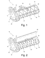
- FIG. 1 a mulching device according to the invention according to a first embodiment is shown in a perspective view.
- the mulching device generally designated 10 contains as a central component a rotor 12, isolated in the FIG. 3 is shown and described in more detail below.
- the mulching device 10 has a drive. This includes in the illustrated embodiment, a hydraulic motor 14 and a V-belt, which connects the hydraulic motor 14 with the rotor 12.
- the V-belt is disposed within a transmission housing 16 and therefore in the FIG. 1 not visible.
- an adjustable front flap 26 which by means of a hydraulic lever 28 of the in the FIG. 1 shown closed position in the in the FIG. 2 shown open position can be converted.
- each mulching tool 34 comprises a working head 36 made of hardened steel.
- the working head 36 is formed at one end of a threaded bolt 38 which extends through a bore 40 of a generally designated 42 holder and is secured by a nut 44 on the bracket 42.
- the holder 42 has a widened foot 46 which tapers towards the bore 40 and is welded to the peripheral surface 32 of the rotor 12.
- the working heads 36 of all mulching tools 34 point in the same tangential direction, so that upon rotation of the rotor 12 in the direction indicated by an arrow 46, the working heads 36 can chop up the material to be processed.
- the mulching apparatus 10 During operation of the mulching apparatus 10, it is fastened to the front of a small and relatively weak motorized carrier vehicle via an unrecognizable attachment device. Via a hose, the hydraulic motor 14 is connected to a hydraulic unit of the carrier vehicle.
- the rotor 12 In order to shred undergrowth, light growths, wood or tree stump, the rotor 12 is rotated about its longitudinal axis, along the direction of rotation explained by the arrow 46.
- the coarse scrub the front flap 26 is first in the in the FIG. 2 shown open position transferred so that the access to the rotor 12 is not hindered.
- the front flap 26 can be closed and the mulching device 10 by means of the carrier vehicle be moved forward or backward, the direction of rotation of the rotor 12 remains unchanged.
- the previously processed material is then picked up again by the rotor 12 and crushed.
- the front flap 26, which is in the closed position, ensures that the material to be processed is repeatedly exposed to the rotating working heads 36 and, as a result, further reduced in size.
- the closed front flap 26 prevents the comminuted material from being whirled away over a large area.
- the mulching device 10 has a weight of about 250 kg and a working width along the longitudinal direction of about 80 cm.
- the diameter of the rotor 12 is preferably between 20 cm and 50 cm and in particular between 25 cm and 40 cm.
- the mulching device 10 is adapted to be attached to carrier vehicles with smaller engines in the range of about 15 kW to 40 kW and preferably between 18 kW and 35 kW.
- the carrier vehicle may be z. B. a embankment mower or a remote controlled equipment carrier. In this way, for example, even steeper slopes of railway lines or roads of scrub and smaller woodland can be exempted without the risk that operators get into danger by tipping devices. Forest mulchers that are carried by tractors or similar large equipment are often too bulky in such steeper and / or rugged terrain and also at risk of tipping.
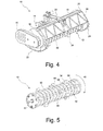
- FIG. 4 shows a mulching device 10 according to a second embodiment in one of the FIG. 1 ajar perspective view. That in the FIG. 4 shown mulching device 10 differs from that in the FIGS. 1 to 3 shown mulching especially by the structure of the rotor 12, the in of the FIG. 5 is shown isolated.
- the rotor 12 in this embodiment comprises a plurality of parallel disks 50 defining interspaces 52 therebetween.
- the mulching tools are here formed as flails 34 'which are freely rotatable about axes of rotation 54 which extend through the spaces 52 between the discs 50.
- the axes of rotation 54 are part of rods 56 which pass through openings 58 in the discs 50 and extend over the entire width of the rotor 12.
- the flails 34 ' may be provided with working surfaces 60 of hardened steel in order to withstand the high loads during the mulching operation permanently.
- the flails 58 can yield by swinging about the axes of rotation 54 to prevent in this way an excessive stress or even a demolition of the flail 34 '.
- the drive consists in the in the FIGS. 4 and 5 shown mulching device 10 from a coupling shaft 60 which is fastened during operation with a shaft stub to a carrier vehicle.
Landscapes
- Life Sciences & Earth Sciences (AREA)
- Biodiversity & Conservation Biology (AREA)
- Ecology (AREA)
- Forests & Forestry (AREA)
- Environmental Sciences (AREA)
- Harvester Elements (AREA)
Applications Claiming Priority (1)
| Application Number | Priority Date | Filing Date | Title |
|---|---|---|---|
| DE202012005722U DE202012005722U1 (de) | 2012-06-13 | 2012-06-13 | Mulchgerät |
Publications (2)
| Publication Number | Publication Date |
|---|---|
| EP2689656A2 true EP2689656A2 (fr) | 2014-01-29 |
| EP2689656A3 EP2689656A3 (fr) | 2014-02-26 |
Family
ID=46671720
Family Applications (1)
| Application Number | Title | Priority Date | Filing Date |
|---|---|---|---|
| EP13003019.0A Withdrawn EP2689656A3 (fr) | 2012-06-13 | 2013-06-13 | Broyeur |
Country Status (2)
| Country | Link |
|---|---|
| EP (1) | EP2689656A3 (fr) |
| DE (1) | DE202012005722U1 (fr) |
Cited By (3)
| Publication number | Priority date | Publication date | Assignee | Title |
|---|---|---|---|---|
| DE102015014225A1 (de) | 2015-11-04 | 2017-05-04 | IRUS Motorgeräte GmbH | Mulchgerät |
| WO2021090339A1 (fr) * | 2019-11-04 | 2021-05-14 | Cangini Benne S.R.L. | Épandeur de paillis |
| WO2023179833A1 (fr) * | 2022-03-22 | 2023-09-28 | Игорь ОХРЕМЧИК | Organe de travail de broyeur forestier (variantes) et broyeur forestier l'utilisant |
Family Cites Families (5)
| Publication number | Priority date | Publication date | Assignee | Title |
|---|---|---|---|---|
| DE3617815A1 (de) | 1986-05-27 | 1987-12-03 | Artur Pieroth | Anbaueinheit fuer einen frontmulcher an einem ackerschlepper |
| WO2003018202A1 (fr) * | 2001-08-31 | 2003-03-06 | Timberline Environmental Services | Tete coupante rotative et ensemble tete coupante |
| US6659378B2 (en) * | 2002-03-13 | 2003-12-09 | Guiseppe Di Anna | Field shredder for pruned branches |
| US7690176B2 (en) * | 2007-04-05 | 2010-04-06 | Shinn Rickey D | Rotary cutter device with integrated cooling system |
| DE102008044866B4 (de) * | 2008-08-28 | 2010-04-29 | Procon Gmbh Maschinen- U. Industrieanlagen | Mobile Holzverarbeitungsanlage |
-
2012
- 2012-06-13 DE DE202012005722U patent/DE202012005722U1/de not_active Expired - Lifetime
-
2013
- 2013-06-13 EP EP13003019.0A patent/EP2689656A3/fr not_active Withdrawn
Cited By (4)
| Publication number | Priority date | Publication date | Assignee | Title |
|---|---|---|---|---|
| DE102015014225A1 (de) | 2015-11-04 | 2017-05-04 | IRUS Motorgeräte GmbH | Mulchgerät |
| DE102015014225B4 (de) * | 2015-11-04 | 2017-08-03 | IRUS Motorgeräte GmbH | Mulchgerät |
| WO2021090339A1 (fr) * | 2019-11-04 | 2021-05-14 | Cangini Benne S.R.L. | Épandeur de paillis |
| WO2023179833A1 (fr) * | 2022-03-22 | 2023-09-28 | Игорь ОХРЕМЧИК | Organe de travail de broyeur forestier (variantes) et broyeur forestier l'utilisant |
Also Published As
| Publication number | Publication date |
|---|---|
| EP2689656A3 (fr) | 2014-02-26 |
| DE202012005722U1 (de) | 2012-07-16 |
Similar Documents
| Publication | Publication Date | Title |
|---|---|---|
| EP3272199B1 (fr) | Broyeur destiné au traitement de résidus de cultures dans un champ | |
| EP3479677B1 (fr) | Dispositif de travail agricole | |
| EP3199010B1 (fr) | Gyrobroyeur de chaume | |
| EP0279076A2 (fr) | Dispositif de broyage | |
| EP2386200A1 (fr) | Ramasseuse-hacheuse automobile | |
| DE202013105582U1 (de) | Landwirtschaftliches Gerät | |
| EP0050218B1 (fr) | Dispositif pour broyer des pierres, particulièrement dans le sol à emploi agricole | |
| EP3469865B1 (fr) | Appareil de paillage pourvu de faucheuse à fléaux et à lames | |
| EP2689656A2 (fr) | Broyeur | |
| EP2792232A1 (fr) | Broyeur et dispositif de ramassage pour materiél à couper | |
| DE102015014225B4 (de) | Mulchgerät | |
| DE2302980A1 (de) | Geraetetraeger fuer rotierende landwirtschaftliche arbeitsgeraete | |
| DE1582840A1 (de) | Schleppergezogenes Strauchrodegeraet | |
| EP0182122A1 (fr) | Faucheuse | |
| DE102008015242B4 (de) | Heckenpflegevorrichtung | |
| DE102016214324A1 (de) | Erntevorsatz mit einem Mulchgerät zur Bearbeitung von auf einem Feld stehenden Pflanzenstümpfen | |
| DE202009001577U1 (de) | Vorrichtung zum Zerkleinern von Pflanzenteilen | |
| DE4431551C2 (de) | Brecher mit einem Gestell, in dem ein angetriebener, steinbrechender Rotor gelagert ist | |
| DE102006020790B4 (de) | Selbstfahrender Feldhäcksler | |
| DE202021102622U1 (de) | Messertrommel insbesondere für einen Feldhäcksler | |
| DE202015106946U1 (de) | Bodenbearbeitungsvorrichtung | |
| DE3842981C2 (fr) | ||
| EP1769663A1 (fr) | Adaptateur de coupe pour une motofaucheuse | |
| DE19633775C2 (de) | Bodenbearbeitungsgerät | |
| DE69715261T2 (de) | Unfallverhütungsvorrichtung für kantentrimmer |
Legal Events
| Date | Code | Title | Description |
|---|---|---|---|
| PUAL | Search report despatched |
Free format text: ORIGINAL CODE: 0009013 |
|
| PUAI | Public reference made under article 153(3) epc to a published international application that has entered the european phase |
Free format text: ORIGINAL CODE: 0009012 |
|
| AK | Designated contracting states |
Kind code of ref document: A2 Designated state(s): AL AT BE BG CH CY CZ DE DK EE ES FI FR GB GR HR HU IE IS IT LI LT LU LV MC MK MT NL NO PL PT RO RS SE SI SK SM TR |
|
| AX | Request for extension of the european patent |
Extension state: BA ME |
|
| AK | Designated contracting states |
Kind code of ref document: A3 Designated state(s): AL AT BE BG CH CY CZ DE DK EE ES FI FR GB GR HR HU IE IS IT LI LT LU LV MC MK MT NL NO PL PT RO RS SE SI SK SM TR |
|
| AX | Request for extension of the european patent |
Extension state: BA ME |
|
| RIC1 | Information provided on ipc code assigned before grant |
Ipc: A01G 23/00 20060101ALI20140121BHEP Ipc: A01G 3/00 20060101AFI20140121BHEP |
|
| STAA | Information on the status of an ep patent application or granted ep patent |
Free format text: STATUS: THE APPLICATION IS DEEMED TO BE WITHDRAWN |
|
| 18D | Application deemed to be withdrawn |
Effective date: 20140827 |