EP2689731A2 - Vorrichtung zum Anbringen eines chirurgischen Befestigungselements mit fluidaktiviertem Auslösemechanismus - Google Patents
Vorrichtung zum Anbringen eines chirurgischen Befestigungselements mit fluidaktiviertem Auslösemechanismus Download PDFInfo
- Publication number
- EP2689731A2 EP2689731A2 EP13178240.1A EP13178240A EP2689731A2 EP 2689731 A2 EP2689731 A2 EP 2689731A2 EP 13178240 A EP13178240 A EP 13178240A EP 2689731 A2 EP2689731 A2 EP 2689731A2
- Authority
- EP
- European Patent Office
- Prior art keywords
- assembly
- distal
- piston
- proximal
- drive
- Prior art date
- Legal status (The legal status is an assumption and is not a legal conclusion. Google has not performed a legal analysis and makes no representation as to the accuracy of the status listed.)
- Granted
Links
- 239000012530 fluid Substances 0.000 title claims description 28
- 230000007246 mechanism Effects 0.000 title description 4
- 238000010304 firing Methods 0.000 title description 2
- 239000012636 effector Substances 0.000 claims abstract description 42
- 230000008878 coupling Effects 0.000 claims description 7
- 238000010168 coupling process Methods 0.000 claims description 7
- 238000005859 coupling reaction Methods 0.000 claims description 7
- 230000010355 oscillation Effects 0.000 claims description 6
- 230000000694 effects Effects 0.000 claims description 4
- 238000005520 cutting process Methods 0.000 description 8
- 230000000881 depressing effect Effects 0.000 description 4
- 230000003213 activating effect Effects 0.000 description 3
- 239000007788 liquid Substances 0.000 description 3
- 238000007789 sealing Methods 0.000 description 3
- 230000008901 benefit Effects 0.000 description 2
- 230000015572 biosynthetic process Effects 0.000 description 2
- 238000012986 modification Methods 0.000 description 2
- 230000004048 modification Effects 0.000 description 2
- 230000002146 bilateral effect Effects 0.000 description 1
- 238000010276 construction Methods 0.000 description 1
- 230000001186 cumulative effect Effects 0.000 description 1
- 230000000994 depressogenic effect Effects 0.000 description 1
- 238000003780 insertion Methods 0.000 description 1
- 230000037431 insertion Effects 0.000 description 1
- 230000003993 interaction Effects 0.000 description 1
- 238000000034 method Methods 0.000 description 1
- 230000008569 process Effects 0.000 description 1
- 230000004044 response Effects 0.000 description 1
- 230000000717 retained effect Effects 0.000 description 1
Images




Classifications
-
- A—HUMAN NECESSITIES
- A61—MEDICAL OR VETERINARY SCIENCE; HYGIENE
- A61B—DIAGNOSIS; SURGERY; IDENTIFICATION
- A61B17/00—Surgical instruments, devices or methods
- A61B17/068—Surgical staplers, e.g. containing multiple staples or clamps
-
- A—HUMAN NECESSITIES
- A61—MEDICAL OR VETERINARY SCIENCE; HYGIENE
- A61B—DIAGNOSIS; SURGERY; IDENTIFICATION
- A61B17/00—Surgical instruments, devices or methods
- A61B17/068—Surgical staplers, e.g. containing multiple staples or clamps
- A61B17/0682—Surgical staplers, e.g. containing multiple staples or clamps for applying U-shaped staples or clamps, e.g. without a forming anvil
- A61B17/0686—Surgical staplers, e.g. containing multiple staples or clamps for applying U-shaped staples or clamps, e.g. without a forming anvil having a forming anvil staying below the tissue during stapling
-
- A—HUMAN NECESSITIES
- A61—MEDICAL OR VETERINARY SCIENCE; HYGIENE
- A61B—DIAGNOSIS; SURGERY; IDENTIFICATION
- A61B17/00—Surgical instruments, devices or methods
- A61B17/068—Surgical staplers, e.g. containing multiple staples or clamps
- A61B17/072—Surgical staplers, e.g. containing multiple staples or clamps for applying a row of staples in a single action, e.g. the staples being applied simultaneously
- A61B17/07207—Surgical staplers, e.g. containing multiple staples or clamps for applying a row of staples in a single action, e.g. the staples being applied simultaneously the staples being applied sequentially
-
- A—HUMAN NECESSITIES
- A61—MEDICAL OR VETERINARY SCIENCE; HYGIENE
- A61B—DIAGNOSIS; SURGERY; IDENTIFICATION
- A61B17/00—Surgical instruments, devices or methods
- A61B2017/00367—Details of actuation of instruments, e.g. relations between pushing buttons, or the like, and activation of the tool, working tip, or the like
- A61B2017/00398—Details of actuation of instruments, e.g. relations between pushing buttons, or the like, and activation of the tool, working tip, or the like using powered actuators, e.g. stepper motors, solenoids
-
- A—HUMAN NECESSITIES
- A61—MEDICAL OR VETERINARY SCIENCE; HYGIENE
- A61B—DIAGNOSIS; SURGERY; IDENTIFICATION
- A61B17/00—Surgical instruments, devices or methods
- A61B2017/00535—Surgical instruments, devices or methods pneumatically or hydraulically operated
- A61B2017/00539—Surgical instruments, devices or methods pneumatically or hydraulically operated hydraulically
-
- A—HUMAN NECESSITIES
- A61—MEDICAL OR VETERINARY SCIENCE; HYGIENE
- A61B—DIAGNOSIS; SURGERY; IDENTIFICATION
- A61B17/00—Surgical instruments, devices or methods
- A61B2017/00535—Surgical instruments, devices or methods pneumatically or hydraulically operated
- A61B2017/00544—Surgical instruments, devices or methods pneumatically or hydraulically operated pneumatically
-
- A—HUMAN NECESSITIES
- A61—MEDICAL OR VETERINARY SCIENCE; HYGIENE
- A61B—DIAGNOSIS; SURGERY; IDENTIFICATION
- A61B17/00—Surgical instruments, devices or methods
- A61B2017/00681—Aspects not otherwise provided for
- A61B2017/00734—Aspects not otherwise provided for battery operated
-
- A—HUMAN NECESSITIES
- A61—MEDICAL OR VETERINARY SCIENCE; HYGIENE
- A61B—DIAGNOSIS; SURGERY; IDENTIFICATION
- A61B17/00—Surgical instruments, devices or methods
- A61B17/068—Surgical staplers, e.g. containing multiple staples or clamps
- A61B17/072—Surgical staplers, e.g. containing multiple staples or clamps for applying a row of staples in a single action, e.g. the staples being applied simultaneously
- A61B2017/07214—Stapler heads
- A61B2017/07278—Stapler heads characterised by its sled or its staple holder
-
- A—HUMAN NECESSITIES
- A61—MEDICAL OR VETERINARY SCIENCE; HYGIENE
- A61B—DIAGNOSIS; SURGERY; IDENTIFICATION
- A61B17/00—Surgical instruments, devices or methods
- A61B17/28—Surgical forceps
- A61B17/29—Forceps for use in minimally invasive surgery
- A61B17/2909—Handles
- A61B2017/2912—Handles transmission of forces to actuating rod or piston
- A61B2017/2923—Toothed members, e.g. rack and pinion
-
- A—HUMAN NECESSITIES
- A61—MEDICAL OR VETERINARY SCIENCE; HYGIENE
- A61B—DIAGNOSIS; SURGERY; IDENTIFICATION
- A61B17/00—Surgical instruments, devices or methods
- A61B17/28—Surgical forceps
- A61B17/29—Forceps for use in minimally invasive surgery
- A61B2017/2926—Details of heads or jaws
- A61B2017/2927—Details of heads or jaws the angular position of the head being adjustable with respect to the shaft
Definitions
- the present disclosure relates to surgical fastener applying apparatus and, more particularly, to a fluid-activated, e.g., pneumatic or hydraulic, surgical fastener applying apparatus for clamping, fastening, and cutting tissue.
- a fluid-activated e.g., pneumatic or hydraulic
- Surgical fastener applying apparatus wherein tissue is first grasped or clamped between opposing jaw structures and then joined by means of surgical fasteners, are well known.
- a knife is provided to cut tissue that has been joined by the fasteners.
- the fasteners are typically in the form of surgical staples, although other surgical fasteners may also be utilized, such as, for example, clips or two part polymeric surgical fasteners.
- Surgical fastener applying apparatus typically include two opposed jaw structures that are used to capture or clamp tissue therebetween.
- one of the jaw structures carries a cartridge assembly which houses a plurality of fasteners arranged in at least two lateral rows, while the other jaw structure includes an anvil which defines a surface for forming the fastener legs as the fasteners are driven from the cartridge assembly.
- the fastener formation process is affected by the interaction between one or more longitudinally moving camming members and a series of individual pushers. As the camming members travel longitudinally through the cartridge assembly, the individual pushers are biased upwardly into a backspan of the fasteners supported within the cartridge assembly to sequentially eject the fasteners from the cartridge.
- a knife is provided, the knife follows the camming members and travels between the fastener rows to cut tissue between the rows of formed fasteners.
- a surgical fastener applying apparatus includes an end effector assembly, a fluid-actuated drive assembly, a drive beam, and a pawl assembly.
- the end effector assembly includes an anvil assembly and a cartridge assembly. One or both of the anvil assembly and the cartridge assembly is movable relative to the other between an open position and a closed position for grasping tissue therebetween.
- the cartridge assembly is configured to retain a plurality of surgical fasteners therein.
- the fluid-actuated drive assembly includes a distal piston member configured to oscillate between a proximal position and a distal position.
- the distal piston member includes a base and a rack extending proximally from the base.
- the rack is slidably disposed within the cartridge assembly.
- the drive beam is configured for translation through the cartridge assembly to eject the plurality of surgical fasteners from the cartridge assembly.
- the pawl assembly couples the drive beam to the rack such that the drive beam is incrementally advanced along the rack and through the cartridge assembly as the distal piston member oscillates between the proximal position and the distal position.
- the fluid-actuated drive assembly includes a distal piston assembly including a piston housing.
- the distal piston member is disposed within the piston housing and is configured such that fluid pressure within the piston housing urges the distal piston member to move from the proximal position to the distal position.
- the distal piston member is biased towards the proximal position such that, in the absence of fluid pressure within the piston housing, the distal piston member is returned from the distal position to the proximal position.
- the drive assembly further includes a proximal piston assembly and an elongated tube coupling the proximal piston assembly and the distal piston member.
- the elongated tube is substantially filled with a fluid such that oscillation of the proximal piston assembly between first and second positions effects oscillation of distal piston member between the proximal and distal positions.
- the surgical fastener applying apparatus further includes a motor assembly coupled to the proximal piston assembly and configured to drive the proximal piston assembly to oscillate between the first and second positions.
- the motor assembly includes an axle and a drive member eccentrically mounted about the axle.
- the motor is configured to rotate the axle such that the drive member is rotated by the axle to drive the proximal piston assembly to oscillate between the first and second positions.
- the drive beam is further configured to engage the anvil assembly and the cartridge assembly upon distal translation of the drive beam to move the end effector assembly from the open position to the closed position.
- the pawl assembly is configured to engage the drive beam to the rack upon movement of the distal piston member from the proximal position to the distal position.
- the pawl assembly is further configured to disengage the drive beam from the rack upon movement of the distal piston member from the distal position back to the proximal position.
- the pawl assembly includes a pawl pivotably coupled to the drive beam.
- the pawl includes a free end configured to engage a tooth of the rack upon movement of the distal piston member from the proximal position to the distal position and configured to slid about teeth of the rack upon movement of the distal piston member from the distal position back to the proximal position.
- the surgical fastener applying apparatus further includes a retraction assembly coupled to the drive beam and the pawl assembly.
- the retraction assembly is selectively actuatable for translating the drive beam proximally through the cartridge assembly.
- the retraction assembly includes a retraction cord coupled to the drive beam and the pawl assembly at a first end thereof.
- the retraction cord has a retraction knob disposed at a second end thereof.
- Fig. 1 is a front, perspective view of an endoscopic, handheld surgical fastener applying apparatus provided in accordance with the present disclosure
- Fig. 2 is side view of the surgical fastener applying apparatus of Fig. 1 , shown with the end effector assembly disposed in an articulated position;
- Fig. 3 is an enlarged, schematic illustration of the area of detail indicated as "3" in Fig. 2 , wherein the motor assembly is disposed in a first position;
- Fig. 4 is an enlarged, schematic illustration of the area of detail indicated as "3" in Fig. 2 , wherein the motor assembly is disposed in a second position;
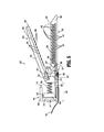
- Fig. 5 is a longitudinal, cross-sectional view of the end effector assembly of the surgical fastener applying apparatus of Fig. 1 , wherein the end effector assembly is disposed in an initial, unclamped, and unfired condition;
- Fig. 6 is an enlarged, side view of the drive beam and rack and pawl system of the end effector assembly of Fig. 5 ;
- Fig. 7 is an enlarged view of the area of detail indicated as "7" in Fig. 6 ;
- Fig. 8 is an enlarged, side view of the drive beam and rack and pawl system of Fig. 6 during advancement of the drive beam along the rack;
- Fig. 9 is a greatly enlarged, side view of the drive beam and rack and pawl system of Fig. 6 during further advancement of the drive beam along the rack;
- Fig. 10 is a longitudinal, cross-sectional view of the end effector assembly of Fig. 5 , wherein the end effector assembly is disposed in a clamped and fully fired condition;
- Fig. 11 is a greatly enlarged, longitudinal, cross-sectional view of the drive beam and rack and pawl system of Fig. 5 during retraction of the drive beam.
- proximal refers to the end of the apparatus or component thereof that is closer to the user
- distal refers to the end of the apparatus or component thereof that is further from the user.
- Surgical fastener applying apparatus 10 is configured as a handheld, endoscopic surgical fastener applying apparatus 10 and generally includes a motorized handle assembly 100 having an elongated member 200 extending distally therefrom and an end effector assembly 300 operably disposed at a distal end of elongated member 200.
- motorized handle assembly 100 having an elongated member 200 extending distally therefrom and an end effector assembly 300 operably disposed at a distal end of elongated member 200.
- suitable surgical fastener applying apparatus e.g., open surgical fastener applying apparatus, manually-powered surgical fastener applying apparatus, etc., are also contemplated for use in accordance with the present disclosure.
- motorized handle assembly 100 of surgical fastener applying apparatus 10 includes a housing 102, one or more actuator buttons 104a for activating end effector assembly 300, e.g., to initiate a clamping, fastening, and/or cutting operation, one or more actuator buttons 104b for articulating end effector assembly 300 relative to elongated member 200 (see Fig. 2 ), and a retraction knob 196 for resetting end effector assembly 300 after a clamping, fastening, and/or cutting operation.
- Housing 102 houses the internal working components of motorized handle assembly 100 and includes an ergonomic handle portion 108, a battery compartment 110, a cylindrical body portion 112, and a distal nose portion 114 extending distally from cylindrical body portion 112. Handle portion 108 is configured to facilitate the operative grasping of housing 102 by the user. A motor assembly 120 and the proximal portion 142 of a drive assembly 140, as will be described in greater detail below, are disposed within distal nose portion 114 of housing 102. Battery compartment 110 is configured to releasably receive a battery pack 116 for providing power to motor assembly 120 and/or articulatable joint assembly 310 of end effector assembly 300.
- Actuator button 104a is electrically coupled between battery pack 116 and motor assembly 110 for selectively activating motor assembly 110 to initiate a clamping, fastening, and cutting operation.
- Motor assembly 120, drive assembly 140, elongated member 200, and end effector assembly 300 will be described in greater detail below. Further discussion of the construction, features, and operation of a suitable motorized handle assembly configured for use with surgical fastener applying apparatus 10 can be found in U.S. Patent Application No. 12/622,827, filed on November 20, 2009 , and entitled "Surgical Console and Hand-held Surgical Device," the entire contents of which are hereby incorporated by reference herein.
- motor assembly 120 includes a motor 122 configured to drive rotation of an axle 124.
- Motor 122 is coupled to battery pack 116 and actuator button 104a such that, upon actuation of actuator button 104a, power is supplied from battery pack 116 to motor 122 to drive axle 124.
- a generally oval-shaped drive member 126 is eccentrically mounted about drive axle 124. That is, drive member 126 is mounted about drive axle 124 such that a first end 128 thereof extends radially-outwardly from axle 124 a greater distance than the second end 130 thereof.
- piston 148 of drive assembly 140 is biased proximally into abutment with drive member 126 of motor assembly 120 such that rotation of the eccentrically mounted drive member 126 by axle 124 urges piston 148 distally against its bias and allows piston 148 to return proximally under bias upon each revolution of drive member 126.
- Drive assembly 140 includes a proximal portion 142 disposed within distal nose portion 114 of housing 102 distally adjacent motor assembly 120, a distal portion 144 disposed within proximal housing 340 of distal tool assembly 330 of end effector assembly 300 (see Fig. 5 ), and an elongated fluid tube 146 extending between the proximal and distal portion 142, 144 ( Fig. 5 ), respectively, of drive assembly 140.
- Proximal portion 142 of drive assembly 140 includes a piston 148, a piston-receiving member 150, e.g., a cylinder, and a biasing member 152 interdisposed between piston 148 and piston-receiving member 150.
- Piston 148 includes a head 154 and a body portion 156 that is slidably disposed within piston-receiving member 150 in sealing relation therewith.
- Biasing member 152 biases head 154 of piston 148 proximally such that body portion 156 of piston 148 is biased outwardly from piston-receiving member 150, although body portion 156 of piston 148 is inhibited from fully backing out of piston-receiving member 150.
- Piston-receiving member 150 defines an internal cavity 158 that communicates at its distal end with elongated fluid tube 146.
- Piston-receiving member 150 further includes a proximal aperture 160 configured, as mentioned above, to slidingly receive body portion 156 of piston 148 in sealing relation therewith.
- Internal cavity 158 of piston-receiving member 150, internal passageway 147 of elongated fluid tube 146, and internal cavity 342 ( Fig. 5 ) of proximal housing 340 ( Fig. 5 ) of distal portion 144 ( Fig. 5 ) of drive assembly 140 cooperate to define a cavity that is substantially filled with a pre-determined volume of fluid "F," e.g., gas or liquid, for, as will be described in detail below, pneumatically or hydraulically actuating end effector assembly 300 ( Fig. 5 ) to clamp, fasten, and/or cut tissue.
- F fluid e.g., gas or liquid
- elongated member 200 extends distally from distal nose portion 114 of motorized handle assembly 100 and interconnects motorized handle assembly 100 and end effector assembly 300. More specifically, elongated member 200 may be configured to releasably engage end effector assembly 300 at the distal end thereof (as shown), e.g., via bayonet coupling, snap-fit, or other suitable engagement mechanism, or may have end effector assembly 300 permanently affixed to the distal end thereof. Elongated member 200 defines a generally tubular configuration for housing elongated fluid tube 146 of drive assembly 140, retraction cord 192 ( Figs.
- retraction assembly 190 and/or any of the other components interconnected between motorized handle assembly 100 and end effector assembly 300, e.g., leads (not shown) for electrically coupling actuator button 104b to articulating joint assembly 320.
- end effector assembly 300 is disposed at the distal end of elongated member 200 and may be releasably engagable with the distal end of elongated member 200.
- End effector assembly 300 includes a proximal shaft portion 310, an articulatable joint assembly 320, and a distal tool assembly 330.
- Proximal shaft portion 310 is configured to releasably engage the distal end of elongated member 200.
- proximal shaft portion 310 may be integral with or otherwise engaged to elongated member 200. It is also contemplated that, in any of the embodiments disclosed herein, the staple cartridge can be a removable and replaceable assembly.
- Articulatable joint assembly 320 of end effector assembly 300 is disposed between proximal shaft portion 310 and distal tool assembly 330.
- Articulatable joint 320 is operably coupled to actuator button 104b of motorized handle assembly 100 such that, upon manipulation of actuator button 104b, end effector assembly 300 may be articulated relative to elongated member 200 in a desired direction.
- articulatable joint assembly 320 may be articulated manually, or by any other suitable mechanical, electrical, or electromechanical mechanism extending between motorized handle assembly 100 and articulatable joint assembly 320.
- articulatable joint assembly 320 may include any suitable articulation mechanism configured to permit articulation of end effector assembly 300 relative to elongated member 200, such as, for example, gears, wires, cables, linkages, and combinations thereof.
- distal tool assembly 330 of end effector assembly 300 includes a proximal housing 340, an anvil assembly 350, and a cartridge assembly 360.
- Proximal housing 340 houses distal portion 144 of drive assembly 140.
- Anvil assembly 350 is pivotably coupled to proximal housing 340 and cartridge assembly 360 such that anvil assembly 350 may be pivoted relative to cartridge assembly 360 between an open position, wherein anvil assembly 350 and cartridge assembly 360 are spaced-apart from one another ( Fig. 5 ), and a closed position, wherein anvil assembly 350 is disposed in close approximation with cartridge assembly 360 to clamp tissue therebetween ( Fig. 10 ).
- Cartridge assembly 360 is mounted, integrally formed, or otherwise fixedly engaged to proximal housing 340 and extends distally therefrom. However, it is also envisioned that this configuration be reversed, e.g., wherein anvil assembly 350 is mounted to proximal housing 340 and cartridge assembly 360 is pivotable relative to anvil assembly 350 and proximal housing 340.
- distal tool assembly 330 may define a bilateral configuration, e.g., wherein both cartridge assembly 360 and anvil assembly 350 are pivotable relative to one another and proximal housing 340.
- proximal housing 340 of distal tool assembly 330 houses the distal portion 144 of drive assembly 140. More specifically, proximal housing 340 defines an internal cavity 342 that communicates at its proximal end with elongated fluid tube 146 and defines an open distal end. A piston base 344 is slidably disposed and sealingly engaged within open distal end of proximal housing 340 such that, as mentioned above, internal cavity 158 of piston-receiving member 150 (see Figs. 3-4 ), internal passageway 147 of elongated fluid tube 146 (see Fig.
- Piston base 344 may be sealingly engaged within the open distal end of proximal housing 340 via an O-ring 345 or via any other suitable sealing engagement.
- Piston base 344 includes a distally-extending piston rack 346 that is configured to translate through elongated cavity 368 of cartridge assembly 360.
- Piston rack 346 includes a plurality of rack teeth 347 disposed along the length thereof. Teeth 347 extend downwardly from piston rack 346 and each defines a vertical, distally-facing surface 348, and an angled, proximally-facing surface 349.
- Distal portion 144 of drive assembly 140 further includes a biasing member 362, e.g., a spring, interdisposed between piston base 344 and cartridge assembly 360 and configured to bias piston base 344 proximally into internal cavity 342 of proximal housing 340.
- a biasing member 362 e.g., a spring
- anvil assembly 350 is pivotably engaged to proximal housing 340 of distal tool assembly 330 at the proximal end of anvil assembly 350 via a pivot pin 351.
- Pivot pin 351 may include a torsion spring (not shown) disposed thereabout.
- any other suitable biasing member may be disposed on or coupled to anvil assembly 350 for biasing anvil assembly 350 towards the open position relative to cartridge assembly 360.
- Anvil assembly 350 generally includes an anvil member 352 and an anvil cover 354.
- Anvil member 352 defines a fastener forming surface that generally opposes the tissue-contacting surface of cartridge assembly 360 when anvil assembly 350 is disposed in the closed position.
- the fastener forming surface of anvil member 352 may include a plurality of fastener pockets 356 configured to receive fasteners 400 and form fasteners 400 about tissue when fasteners 400 are driven from cartridge assembly 360 into fastener pockets 356 of anvil member 352.
- Anvil member 352 further includes an elongated vertically-oriented slot (not shown) that is configured to receive vertical support strut 372 of drive beam 370 and an elongated horizontally-oriented slot 359 that is configured to receive upper transverse bar 374 of drive beam 370, as will be described in greater detail below.
- Cartridge assembly 360 of distal tool assembly 330 includes a base member 362 defining a tissue-contacting surface and a plurality of vertical slots (not shown) arranged in rows along the tissue-contacting surface thereof.
- Each vertical slot (not shown) is configured to house a fastener 400, such as a staple or clip, therein.
- a pusher 364 is disposed within each of the vertical slots (not shown) and is configured to abut the backspan of the respective fastener 400.
- Each pusher 364 defines a proximally-facing cam surface 365 that is configured to facilitate the upward urging of pushers 364 in response to longitudinal translation of drive sled 366 to eject fasteners 400 from cartridge assembly 360.
- Cartridge assembly 360 further includes an elongated, vertically-oriented central slot (not shown) that is configured to receive vertical support strut 372 of drive beam 370, and an elongated cavity 368 configured to slidably receive the distally-extending piston rack 346 of drive assembly 140 and slidably retain drive sled 366, as will be described in greater detail below.
- Drive sled 366 defines an angled distal surface 367 that is configured to contact proximally-facing cam surfaces 365 of pushers 364 upon translation through elongated cavity 368 of base member 362 of cartridge assembly 360 to facilitate the upward urging of pushers 364 to eject fasteners 400 from cartridge assembly 360.
- distal tool assembly 330 further includes a drive beam 370 that is selectively translatable through and relative to cartridge assembly 360 and anvil assembly 350 to pivot anvil assembly 350 to the closed position for clamping tissue between cartridge assembly 360 and anvil assembly 350; eject the plurality of fasteners 400 from cartridge assembly 360, through the clamped tissue, and into fastener pockets 356 to form fasteners 400 about tissue; and cut tissue clamped between cartridge assembly 360 and anvil assembly 350 between the rows of formed fasteners 400.
- Drive beam 370 includes a vertical support strut 372, an upper transverse bar 374 disposed at one end of vertical support strut 372, and a lower transverse bar 376 disposed at the opposite end of vertical support strut 372.
- Vertical support strut 372 is configured for translation through the elongated vertically-oriented slots (not shown) of anvil assembly 350 and cartridge assembly 360 and defines a cutting edge or knife 378 positioned to cut tissue clamped between anvil assembly 350 and cartridge assembly 360 upon translation therethrough.
- Upper transverse bar 374 is configured for translation through horizontally-oriented slot 359 of anvil assembly 350.
- Lower transverse bar 376 is configured for translation about the bottom, exterior surface of cartridge assembly 360.
- drive beam 370 further includes a pawl assembly 380 and a retraction assembly 190 coupled towards the bottom end thereof, e.g., coupled to lower transverse bar 376.
- Pawl assembly 380 includes a pawl 382 that is pivotably coupled to drive beam 370 at a first end thereof via a pivot pin 384.
- the second, free end of pawl 382 defines a vertical engagement surface 385 and an angled engagement surface 386 that, as will be described below, facilitate the one-way advancement of drive beam 370 through cartridge assembly 360 to clamp, fasten, and/or cut tissue.
- Pawl assembly 380 further includes a biasing member 388, e.g., a spring, that is provided to bias the second, free end of pawl 382 in a generally upward direction into engagement with teeth 347 of piston rack 346.
- retraction assembly 190 includes a pin 197 slidably engaged within a longitudinal slot 198 defined within lower transverse bar 376 of drive beam 370 (or other suitable portion thereof).
- Retraction cord 192 is coupled to pin 197 and, as mentioned above, extends proximally through end effector assembly 300, elongated member 200, and cylindrical body portion 112 of housing 102 of motorized handle assembly 100, ultimately engaging retraction knob 196, which extends proximally from cylindrical body portion 112 of housing 102.
- retraction cord 192 may define proximal and distal sections that are releasably engagable with one another to permit releasable engagement of end effector assembly 300 and elongated member 200.
- Pin 197 is initially disposed at a distal end 199a of slot 198 such that pin 197 is spaced-apart from distal protrusion 389, which extends distally from the first end of pawl 382.
- pin 197 is translated proximally through slot 198 towards the proximal end 199b thereof to urge the second, free end of pawl 382 to rotate downwardly out of engagement with distally-extending piston rack 346 of drive assembly 140 ( Figs. 3-4 ) and permit drive beam 370 to return proximally through cartridge assembly 360 back to its initial position.
- drive beam 370 is disposed at the proximal end of cartridge assembly 360 and is positioned proximally of horizontally-oriented slot 359 defined within anvil assembly 350 such that anvil assembly 350 is disposed in the spaced-apart position relative to cartridge assembly 360.
- This position corresponds to the initial, unclamped, and un-actuated condition of surgical fastener applying apparatus 10. Further, in this initial, unclamped, un-actuated condition, as shown in Figs.
- piston 148 is biased proximally from piston-receiving member 150 under the bias of biasing member 152
- piston base 344 is biased proximally into proximal housing 340
- piston rack 346 is disposed in a more-proximal position within elongated cavity 368 of cartridge assembly 360
- drive sled 366 is disposed within elongated cavity 368 at the proximal end thereof.
- end effector assembly 300 may be actuated.
- one or more of actuator buttons 104a are actuated, e.g., depressed, to activate motor 122 which, in turn, drives drive axle 124 to rotate drive member 126.
- motor 122 drives drive axle 124 to rotate drive member 126.
- first end 128 of drive member 126 contacts head 154 of piston 148 and urges body 156 of piston 148 distally into internal cavity 158 of piston-receiving member 150, against the bias of biasing member 152.
- drive member 126 Upon further rotation of drive member 126 by drive axle 124, second end 130 of drive member 126 is positioned adjacent piston 148, allowing piston 148 to return proximally under the bias of biasing member 152 such that body 156 is retracted proximally relative to internal cavity 158 of piston-receiving member 150.
- drive member 126 While motor 122 remains in an activated state, drive member 126 is repeatedly rotated by axle 124 such that piston 148 is repeatedly urged distally into piston-receiving member 150 and returned proximally, thus establishing a pulsed actuation configuration of drive assembly 140.
- piston rack 346 which is engaged to and extends distally from piston base 344, is translated distally through elongated cavity 368 of cartridge assembly 360.
- drive beam 370 is likewise pushed distally due to the abutting engagement between the vertical, distally-facing surface 348 of one of the teeth 347 of piston rack 346 with the vertical engagement surface 385 of the second end of pawl 382.
- Distal translation of drive beam 370 through cartridge assembly 360 urges sled 366 distally. That is, each pulsed actuation of drive assembly 140 urges drive beam 370 and sled 366 distally through cartridge assembly 360 an incremental step distance.
- the cumulative effect of the incremental advancements of drive beam 370 and sled 366 upon repeated pulsed actuation of drive assembly 140 will be described in greater detail below.
- drive member 126 is repeatedly rotated by axle 124 such that piston 148 is repeatedly urged distally into piston-receiving member 150 by first end 128 of drive member 126 and returned proximally under the bias of biasing member 152, thus establishing the pulsed actuation of drive assembly 140.
- the distal translation of piston base 344 and piston rack 346 upon distal urging of piston 148 into piston-receiving member 150 to incrementally advance drive beam 370 and sled 366 through cartridge assembly 360 is described above.
- piston 148 is permitted to return proximally under the bias of biasing member 152.
- the pressure or force of the fluid "F” no longer urges piston base 344 distally, thus allowing piston base 344 to return proximally under the bias of biasing member 162.
- the proximal return of piston base 344 pulls piston rack 346 proximally.
- teeth 347 of piston rack 346 are slid proximally past pawl 382. That is, although piston rack 346 is returned proximally, teeth 347 are slid proximally past pawl 382 such that drive beam 370 is retained in position relative to cartridge assembly 360. More specifically, as piston rack 346 is returned proximally, angled surfaces 349 of teeth 347 cam along angled engagement surface 386 of pawl 382 and urge the second, free end of pawl 382 downwardly against the bias of biasing member 388 to allow piston rack 346 to slide proximally relative to pawl 382.
- drive beam 370 The frictional engagement of drive beam 370 within anvil assembly 350 and cartridge assembly 360 is sufficient to retain drive beam 370 in substantially fixed position upon proximal retraction of piston rack 346. Since drive beam 370 is maintained in position, sled 366 ( Fig. 5 ), which is positioned distally adjacent drive beam 370, is likewise maintained in position during proximal retraction of piston rack 346.
- the above-described pawl and rack system provides for incremental advancement of drive beam 370 and sled 366 through cartridge assembly 360 upon each pulse of actuation of drive assembly 140.
- Repeated pulses of actuation of drive assembly 140 effect the sequential clamping of tissue between anvil assembly 350 and cartridge assembly 360, ejection of fasteners 400 from cartridge assembly 360 through tissue and into anvil assembly 350 for formation about tissue, and cutting of tissue between the rows of formed fasteners 400.
- drive beam 370 is disposed at the proximal end of cartridge assembly 360 and is positioned proximally of horizontally-oriented slot 359 defined within anvil assembly 350 such that pawl 382 is engaged with one of the proximally-disposed teeth 347 of piston rack 346.
- Sled 366 is initially disposed at the proximal end of cartridge assembly 360, distally adjacent drive beam 370.
- piston base 344 and piston rack 346 are urged distally such that drive beam 370 and sled 366 are likewise urged distally.
- pawl assembly 380 Upon retraction of piston rack 346, pawl assembly 380 is slid along piston rack 346 until pawl 382 is engaged with a more-distally disposed tooth 347 of piston rack 346.
- the above-described incremental advancement of drive beam 370 and sled 366 can be repeated to further advance drive beam 370 and sled 366, with pawl 382 engaging a more-distally disposed tooth 347 of piston rack 346 after each repetition.
- drive beam 370 and sled 366 are advanced distally through cartridge assembly 360 and distally along piston rack 346 as piston rack 346 is repeatedly oscillated between proximal and distal positions by the pulsed activating of drive assembly 140 ( Figs. 3-5 ).
- drive beam 370 Upon further distal advancement of drive beam 370, drive beam 370 is urged into contact with sled 366 to likewise urge sled 366 distally.
- sled 366 As sled 366 is urged distally, angled surface 367 of sled 366 is sequentially urged into contact with angled surfaces 365 of pushers 364 to sequentially eject fasteners 400 from cartridge assembly 360, through tissue clamped between cartridge assembly 360 and anvil assembly 350, and into contact with anvil pockets 356 of anvil assembly 350 to form fasteners 400 about the clamped tissue.
- Knife 378 which is defined on vertical support strut 372 of drive beam 370, is positioned to follow slightly behind sled 366 to cut tissue between the rows of formed fasteners 400.
- actuation of drive assembly 140 may be controlled to fire greater or fewer fasteners 400 from cartridge assembly 360, depending on a particular purpose. That is, drive beam 370 and sled 366 may be fully advanced through cartridge assembly 360, e.g., by fully depressing actuator button 104a ( Fig. 1 ) or depressing actuator button 104a ( Fig. 1 ) for a relatively longer period of time, to fire all of the fasteners 400 from cartridge assembly 360, or may only be actuated partially, e.g., by only partially depressing actuator button 104a ( Fig. 1 ) or depressing actuator button 104a ( Fig. 1 ) for a relatively shorter period of time, to fire only a portion of the plurality of fasteners 400 disposed within cartridge assembly 360.
- drive beam 370 may be retracted back to its initial position to allow anvil assembly 350 to return to the spaced-apart position such that surgical fastener applying apparatus 10 may be removed from the surgical site.
- retraction knob 196 is pulled proximally relative to motorized handle assembly 100 such that retraction cord 192 is translated proximally through surgical fastener applying apparatus 10.
- pin 197 is translated proximally through slot 198 from the distal end 199a towards the proximal end 199b thereof.
- pin 197 Upon proximal translation of pin 197 through slot 198, pin 197 ultimately contacts distal protrusion 389 of pawl 382 and urges distal protrusion 389 proximally such that the second, free end of pawl 382 is rotated downwardly against the bias of biasing member 388 and out of engagement with piston rack 346. With pawl 382 no longer engaged with teeth 347 of piston rack 346, retraction cord 192 may be pulled further proximally to translate drive beam 370 proximally through cartridge assembly 360 back to its initial position.
- the end effector assembly and motor assembly can be mechanically connected by pushers, rods, linkages or the like, in any of the embodiments disclosed herein.
- the end effector assembly may also be driven, in any of the embodiments disclosed herein, via manual power.
- the end effector assembly can be driven by a source of pressurized fluid, in the embodiments disclosed herein. Therefore, the above description should not be construed as limiting, but merely as exemplifications of embodiments. Those skilled in the art will envision other modifications within the scope and spirit of the present disclosure.
Landscapes
- Health & Medical Sciences (AREA)
- Life Sciences & Earth Sciences (AREA)
- Surgery (AREA)
- Heart & Thoracic Surgery (AREA)
- Engineering & Computer Science (AREA)
- Biomedical Technology (AREA)
- Nuclear Medicine, Radiotherapy & Molecular Imaging (AREA)
- Medical Informatics (AREA)
- Molecular Biology (AREA)
- Animal Behavior & Ethology (AREA)
- General Health & Medical Sciences (AREA)
- Public Health (AREA)
- Veterinary Medicine (AREA)
- Surgical Instruments (AREA)
Applications Claiming Priority (2)
| Application Number | Priority Date | Filing Date | Title |
|---|---|---|---|
| US201261676408P | 2012-07-27 | 2012-07-27 | |
| US13/915,891 US9301757B2 (en) | 2012-07-27 | 2013-06-12 | Surgical fastener applying apparatus including fluid-activated firing mechanism |
Publications (3)
| Publication Number | Publication Date |
|---|---|
| EP2689731A2 true EP2689731A2 (de) | 2014-01-29 |
| EP2689731A3 EP2689731A3 (de) | 2015-11-04 |
| EP2689731B1 EP2689731B1 (de) | 2020-04-15 |
Family
ID=48875586
Family Applications (1)
| Application Number | Title | Priority Date | Filing Date |
|---|---|---|---|
| EP13178240.1A Active EP2689731B1 (de) | 2012-07-27 | 2013-07-26 | Vorrichtung zum Anbringen eines chirurgischen Befestigungselements mit fluidaktiviertem Auslösemechanismus |
Country Status (7)
| Country | Link |
|---|---|
| US (2) | US9301757B2 (de) |
| EP (1) | EP2689731B1 (de) |
| JP (1) | JP2014028144A (de) |
| CN (1) | CN103654897A (de) |
| AU (1) | AU2013206803A1 (de) |
| CA (1) | CA2818854A1 (de) |
| ES (1) | ES2790976T3 (de) |
Cited By (1)
| Publication number | Priority date | Publication date | Assignee | Title |
|---|---|---|---|---|
| WO2021102128A3 (en) * | 2019-11-20 | 2021-06-24 | Boston Scientific Scimed, Inc. | Pneumatic or hydraulic powered tissue closure devices |
Families Citing this family (165)
| Publication number | Priority date | Publication date | Assignee | Title |
|---|---|---|---|---|
| CN110063762B (zh) | 2013-11-04 | 2022-04-15 | 柯惠Lp公司 | 手术紧固件施加装置 |
| CN105682568B (zh) | 2013-11-04 | 2018-10-23 | 柯惠Lp公司 | 手术紧固件施加装置 |
| CA2926748A1 (en) | 2013-11-04 | 2015-05-07 | Covidien Lp | Surgical fastener applying apparatus |
| EP3142569B1 (de) | 2014-05-15 | 2023-12-27 | Covidien LP | Vorrichtung zum anbringen eines chirurgischen befestigungselements |
| US10456132B2 (en) | 2014-06-25 | 2019-10-29 | Ethicon Llc | Jaw opening feature for surgical stapler |
| US10039545B2 (en) | 2015-02-23 | 2018-08-07 | Covidien Lp | Double fire stapling |
| US10085749B2 (en) | 2015-02-26 | 2018-10-02 | Covidien Lp | Surgical apparatus with conductor strain relief |
| US10285698B2 (en) | 2015-02-26 | 2019-05-14 | Covidien Lp | Surgical apparatus |
| US10463368B2 (en) | 2015-04-10 | 2019-11-05 | Covidien Lp | Endoscopic stapler |
| CA2986480A1 (en) | 2015-05-25 | 2016-12-01 | Covidien Lp | Small diameter surgical stapling device |
| US10349941B2 (en) | 2015-05-27 | 2019-07-16 | Covidien Lp | Multi-fire lead screw stapling device |
| US10172615B2 (en) | 2015-05-27 | 2019-01-08 | Covidien Lp | Multi-fire push rod stapling device |
| US10064622B2 (en) | 2015-07-29 | 2018-09-04 | Covidien Lp | Surgical stapling loading unit with stroke counter and lockout |
| US10045782B2 (en) | 2015-07-30 | 2018-08-14 | Covidien Lp | Surgical stapling loading unit with stroke counter and lockout |
| US10213204B2 (en) | 2015-10-02 | 2019-02-26 | Covidien Lp | Micro surgical instrument and loading unit for use therewith |
| US10772632B2 (en) | 2015-10-28 | 2020-09-15 | Covidien Lp | Surgical stapling device with triple leg staples |
| US10973517B2 (en) | 2015-11-13 | 2021-04-13 | Intuitive Surgical Operations, Inc. | Stapler with composite cardan and screw drive |
| US10595864B2 (en) | 2015-11-24 | 2020-03-24 | Covidien Lp | Adapter assembly for interconnecting electromechanical surgical devices and surgical loading units, and surgical systems thereof |
| US10111660B2 (en) | 2015-12-03 | 2018-10-30 | Covidien Lp | Surgical stapler flexible distal tip |
| US10966717B2 (en) | 2016-01-07 | 2021-04-06 | Covidien Lp | Surgical fastener apparatus |
| US10660623B2 (en) | 2016-01-15 | 2020-05-26 | Covidien Lp | Centering mechanism for articulation joint |
| US10349937B2 (en) | 2016-02-10 | 2019-07-16 | Covidien Lp | Surgical stapler with articulation locking mechanism |
| US10420559B2 (en) | 2016-02-11 | 2019-09-24 | Covidien Lp | Surgical stapler with small diameter endoscopic portion |
| US10285700B2 (en) * | 2016-04-20 | 2019-05-14 | Ethicon Llc | Surgical staple cartridge with hydraulic staple deployment |
| US10561419B2 (en) | 2016-05-04 | 2020-02-18 | Covidien Lp | Powered end effector assembly with pivotable channel |
| US11065022B2 (en) | 2016-05-17 | 2021-07-20 | Covidien Lp | Cutting member for a surgical instrument |
| US10631857B2 (en) | 2016-11-04 | 2020-04-28 | Covidien Lp | Loading unit for surgical instruments with low profile pushers |
| US11642126B2 (en) | 2016-11-04 | 2023-05-09 | Covidien Lp | Surgical stapling apparatus with tissue pockets |
| US10492784B2 (en) | 2016-11-08 | 2019-12-03 | Covidien Lp | Surgical tool assembly with compact firing assembly |
| US10463371B2 (en) | 2016-11-29 | 2019-11-05 | Covidien Lp | Reload assembly with spent reload indicator |
| US10709901B2 (en) | 2017-01-05 | 2020-07-14 | Covidien Lp | Implantable fasteners, applicators, and methods for brachytherapy |
| US10952767B2 (en) | 2017-02-06 | 2021-03-23 | Covidien Lp | Connector clip for securing an introducer to a surgical fastener applying apparatus |
| US20180235618A1 (en) | 2017-02-22 | 2018-08-23 | Covidien Lp | Loading unit for surgical instruments with low profile pushers |
| US10849621B2 (en) | 2017-02-23 | 2020-12-01 | Covidien Lp | Surgical stapler with small diameter endoscopic portion |
| US11350915B2 (en) | 2017-02-23 | 2022-06-07 | Covidien Lp | Surgical stapler with small diameter endoscopic portion |
| US10299790B2 (en) | 2017-03-03 | 2019-05-28 | Covidien Lp | Adapter with centering mechanism for articulation joint |
| US10660641B2 (en) | 2017-03-16 | 2020-05-26 | Covidien Lp | Adapter with centering mechanism for articulation joint |
| US10603035B2 (en) | 2017-05-02 | 2020-03-31 | Covidien Lp | Surgical loading unit including an articulating end effector |
| US11324502B2 (en) | 2017-05-02 | 2022-05-10 | Covidien Lp | Surgical loading unit including an articulating end effector |
| US10524784B2 (en) | 2017-05-05 | 2020-01-07 | Covidien Lp | Surgical staples with expandable backspan |
| US10390826B2 (en) | 2017-05-08 | 2019-08-27 | Covidien Lp | Surgical stapling device with elongated tool assembly and methods of use |
| US10420551B2 (en) | 2017-05-30 | 2019-09-24 | Covidien Lp | Authentication and information system for reusable surgical instruments |
| US10478185B2 (en) | 2017-06-02 | 2019-11-19 | Covidien Lp | Tool assembly with minimal dead space |
| US11382638B2 (en) * | 2017-06-20 | 2022-07-12 | Cilag Gmbh International | Closed loop feedback control of motor velocity of a surgical stapling and cutting instrument based on measured time over a specified displacement distance |
| US10624636B2 (en) | 2017-08-23 | 2020-04-21 | Covidien Lp | Surgical stapling device with floating staple cartridge |
| US10806452B2 (en) | 2017-08-24 | 2020-10-20 | Covidien Lp | Loading unit for a surgical stapling instrument |
| US11331099B2 (en) | 2017-09-01 | 2022-05-17 | Rev Medica, Inc. | Surgical stapler with removable power pack and interchangeable battery pack |
| US10695060B2 (en) | 2017-09-01 | 2020-06-30 | RevMedica, Inc. | Loadable power pack for surgical instruments |
| US10966720B2 (en) | 2017-09-01 | 2021-04-06 | RevMedica, Inc. | Surgical stapler with removable power pack |
| US11090075B2 (en) * | 2017-10-30 | 2021-08-17 | Cilag Gmbh International | Articulation features for surgical end effector |
| US10925603B2 (en) | 2017-11-14 | 2021-02-23 | Covidien Lp | Reload with articulation stabilization system |
| US10863987B2 (en) | 2017-11-16 | 2020-12-15 | Covidien Lp | Surgical instrument with imaging device |
| US10945732B2 (en) | 2018-01-17 | 2021-03-16 | Covidien Lp | Surgical stapler with self-returning assembly |
| CN111801055B (zh) | 2018-03-02 | 2024-07-05 | 柯惠有限合伙公司 | 外科缝合器械 |
| US10849622B2 (en) | 2018-06-21 | 2020-12-01 | Covidien Lp | Articulated stapling with fire lock |
| US10736631B2 (en) | 2018-08-07 | 2020-08-11 | Covidien Lp | End effector with staple cartridge ejector |
| US10849620B2 (en) | 2018-09-14 | 2020-12-01 | Covidien Lp | Connector mechanisms for surgical stapling instruments |
| US11510669B2 (en) | 2020-09-29 | 2022-11-29 | Covidien Lp | Hand-held surgical instruments |
| US11090051B2 (en) | 2018-10-23 | 2021-08-17 | Covidien Lp | Surgical stapling device with floating staple cartridge |
| US11197734B2 (en) | 2018-10-30 | 2021-12-14 | Covidien Lp | Load sensing devices for use in surgical instruments |
| US11197673B2 (en) | 2018-10-30 | 2021-12-14 | Covidien Lp | Surgical stapling instruments and end effector assemblies thereof |
| WO2020131290A1 (en) | 2018-12-21 | 2020-06-25 | Intuitive Surgical Operations, Inc. | Articulation assemblies for surgical instruments |
| WO2020131685A1 (en) | 2018-12-21 | 2020-06-25 | Intuitive Surgical Operations, Inc. | Surgical instruments with switches for deactivating and/or identifying stapler cartridges |
| US10912563B2 (en) | 2019-01-02 | 2021-02-09 | Covidien Lp | Stapling device including tool assembly stabilizing member |
| US11344297B2 (en) | 2019-02-28 | 2022-05-31 | Covidien Lp | Surgical stapling device with independently movable jaws |
| US11259808B2 (en) | 2019-03-13 | 2022-03-01 | Covidien Lp | Tool assemblies with a gap locking member |
| US11284893B2 (en) | 2019-04-02 | 2022-03-29 | Covidien Lp | Stapling device with articulating tool assembly |
| US11284892B2 (en) | 2019-04-02 | 2022-03-29 | Covidien Lp | Loading unit and adapter with modified coupling assembly |
| US11241228B2 (en) | 2019-04-05 | 2022-02-08 | Covidien Lp | Surgical instrument including an adapter assembly and an articulating surgical loading unit |
| WO2020214258A1 (en) | 2019-04-15 | 2020-10-22 | Intuitive Surgical Operations, Inc. | Staple cartridge for a surgical instrument |
| CN119745453A (zh) | 2019-05-31 | 2025-04-04 | 直观外科手术操作公司 | 用于外科器械的订合钉仓 |
| EP3998960A4 (de) | 2019-07-19 | 2022-12-14 | Revmedica, Inc. | Chirurgisches klammergerät mit abnehmbarem netzteil |
| US12290257B2 (en) | 2019-07-19 | 2025-05-06 | RevMedica, Inc. | Surgical clip applier with removable power pack |
| US12279770B2 (en) | 2019-07-19 | 2025-04-22 | RevMedica, Inc. | Power pack for activating surgical instruments and providing user feedback |
| US12279771B2 (en) | 2019-07-19 | 2025-04-22 | RevMedica, Inc. | Power pack for activating surgical instruments and providing user feedback |
| US11224424B2 (en) | 2019-08-02 | 2022-01-18 | Covidien Lp | Linear stapling device with vertically movable knife |
| US11406385B2 (en) | 2019-10-11 | 2022-08-09 | Covidien Lp | Stapling device with a gap locking member |
| US11123068B2 (en) | 2019-11-08 | 2021-09-21 | Covidien Lp | Surgical staple cartridge |
| US11974743B2 (en) | 2019-12-02 | 2024-05-07 | Covidien Lp | Linear stapling device with a gap locking member |
| US11707274B2 (en) | 2019-12-06 | 2023-07-25 | Covidien Lp | Articulating mechanism for surgical instrument |
| US11109862B2 (en) | 2019-12-12 | 2021-09-07 | Covidien Lp | Surgical stapling device with flexible shaft |
| US12383260B2 (en) | 2019-12-13 | 2025-08-12 | Covidien Lp | Surgical stapler with universal tip reload |
| US11737747B2 (en) | 2019-12-17 | 2023-08-29 | Covidien Lp | Hand-held surgical instruments |
| WO2021141971A1 (en) | 2020-01-07 | 2021-07-15 | Intuitive Surgical Operations, Inc. | Surgical instruments for applying multiple clips |
| US11642129B2 (en) | 2020-01-15 | 2023-05-09 | Intuitive Surgical Operations, Inc. | Staple cartridge and drive member for surgical instrument |
| US11278282B2 (en) | 2020-01-31 | 2022-03-22 | Covidien Lp | Stapling device with selective cutting |
| US11452524B2 (en) | 2020-01-31 | 2022-09-27 | Covidien Lp | Surgical stapling device with lockout |
| CN115052539B (zh) | 2020-02-03 | 2025-08-08 | 柯惠有限合伙公司 | 外科缝合装置 |
| US11890014B2 (en) | 2020-02-14 | 2024-02-06 | Covidien Lp | Cartridge holder for surgical staples and having ridges in peripheral walls for gripping tissue |
| CN115103642B (zh) | 2020-02-14 | 2025-12-30 | 柯惠有限合伙公司 | 手术钉合装置 |
| US11344301B2 (en) | 2020-03-02 | 2022-05-31 | Covidien Lp | Surgical stapling device with replaceable reload assembly |
| US11344302B2 (en) | 2020-03-05 | 2022-05-31 | Covidien Lp | Articulation mechanism for surgical stapling device |
| US11246593B2 (en) | 2020-03-06 | 2022-02-15 | Covidien Lp | Staple cartridge |
| US11707278B2 (en) | 2020-03-06 | 2023-07-25 | Covidien Lp | Surgical stapler tool assembly to minimize bleeding |
| US11317911B2 (en) | 2020-03-10 | 2022-05-03 | Covidien Lp | Tool assembly with replaceable cartridge assembly |
| US11357505B2 (en) | 2020-03-10 | 2022-06-14 | Covidien Lp | Surgical stapling apparatus with firing lockout mechanism |
| US11406383B2 (en) | 2020-03-17 | 2022-08-09 | Covidien Lp | Fire assisted powered EGIA handle |
| JP7490802B2 (ja) | 2020-03-24 | 2024-05-27 | コヴィディエン リミテッド パートナーシップ | 交換可能なステープルカートリッジを備える外科用ステープル留め装置 |
| US11331098B2 (en) | 2020-04-01 | 2022-05-17 | Covidien Lp | Sled detection device |
| US11426159B2 (en) | 2020-04-01 | 2022-08-30 | Covidien Lp | Sled detection device |
| US11504117B2 (en) | 2020-04-02 | 2022-11-22 | Covidien Lp | Hand-held surgical instruments |
| US11937794B2 (en) | 2020-05-11 | 2024-03-26 | Covidien Lp | Powered handle assembly for surgical devices |
| US11191537B1 (en) | 2020-05-12 | 2021-12-07 | Covidien Lp | Stapling device with continuously parallel jaws |
| US11406387B2 (en) | 2020-05-12 | 2022-08-09 | Covidien Lp | Surgical stapling device with replaceable staple cartridge |
| US11534167B2 (en) | 2020-05-28 | 2022-12-27 | Covidien Lp | Electrotaxis-conducive stapling |
| US11191538B1 (en) | 2020-06-08 | 2021-12-07 | Covidien Lp | Surgical stapling device with parallel jaw closure |
| US11844517B2 (en) | 2020-06-25 | 2023-12-19 | Covidien Lp | Linear stapling device with continuously parallel jaws |
| US11324500B2 (en) | 2020-06-30 | 2022-05-10 | Covidien Lp | Surgical stapling device |
| US12023027B2 (en) | 2020-07-02 | 2024-07-02 | Covidien Lp | Surgical stapling device with compressible staple cartridge |
| US12349902B2 (en) | 2020-07-09 | 2025-07-08 | Covidien Lp | Powered handle assembly for surgical devices |
| US11517305B2 (en) | 2020-07-09 | 2022-12-06 | Covidien Lp | Contoured staple pusher |
| US11446028B2 (en) | 2020-07-09 | 2022-09-20 | Covidien Lp | Tool assembly with pivotable clamping beam |
| US12089838B2 (en) | 2020-07-21 | 2024-09-17 | Covidien Lp | Shipping cover for staple cartridge |
| US11266402B2 (en) | 2020-07-30 | 2022-03-08 | Covidien Lp | Sensing curved tip for surgical stapling instruments |
| US11439392B2 (en) | 2020-08-03 | 2022-09-13 | Covidien Lp | Surgical stapling device and fastener for pathological exam |
| US11395654B2 (en) | 2020-08-07 | 2022-07-26 | Covidien Lp | Surgical stapling device with articulation braking assembly |
| US11602342B2 (en) | 2020-08-27 | 2023-03-14 | Covidien Lp | Surgical stapling device with laser probe |
| US11678878B2 (en) | 2020-09-16 | 2023-06-20 | Covidien Lp | Articulation mechanism for surgical stapling device |
| US11660092B2 (en) | 2020-09-29 | 2023-05-30 | Covidien Lp | Adapter for securing loading units to handle assemblies of surgical stapling instruments |
| US11406384B2 (en) | 2020-10-05 | 2022-08-09 | Covidien Lp | Stapling device with drive assembly stop member |
| US11576674B2 (en) | 2020-10-06 | 2023-02-14 | Covidien Lp | Surgical stapling device with articulation lock assembly |
| US11890007B2 (en) | 2020-11-18 | 2024-02-06 | Covidien Lp | Stapling device with flex cable and tensioning mechanism |
| US11737774B2 (en) | 2020-12-04 | 2023-08-29 | Covidien Lp | Surgical instrument with articulation assembly |
| US11819200B2 (en) | 2020-12-15 | 2023-11-21 | Covidien Lp | Surgical instrument with articulation assembly |
| CN112339871B (zh) * | 2020-12-18 | 2022-06-17 | 徐工集团工程机械股份有限公司科技分公司 | 滑移转向装载机用机罩限位机构 |
| US11553914B2 (en) | 2020-12-22 | 2023-01-17 | Covidien Lp | Surgical stapling device with parallel jaw closure |
| US12336708B2 (en) | 2020-12-23 | 2025-06-24 | Covidien Lp | Surgical instrument including a decoupling mechanism |
| CN112656472A (zh) * | 2020-12-25 | 2021-04-16 | 常州安康医疗器械有限公司 | 一种具有击发保险的腔镜吻合器 |
| US11744582B2 (en) | 2021-01-05 | 2023-09-05 | Covidien Lp | Surgical stapling device with firing lockout mechanism |
| US11759206B2 (en) | 2021-01-05 | 2023-09-19 | Covidien Lp | Surgical stapling device with firing lockout mechanism |
| EP4274492B1 (de) | 2021-01-08 | 2026-01-28 | Intuitive Surgical Operations, Inc. | Chirurgisches instrument mit linearen und handnahtklammern mit saiten |
| WO2022150215A1 (en) | 2021-01-08 | 2022-07-14 | Intuitive Surgical Operations, Inc. | Surgical stapling instruments |
| US11517313B2 (en) | 2021-01-27 | 2022-12-06 | Covidien Lp | Surgical stapling device with laminated drive member |
| US11759207B2 (en) | 2021-01-27 | 2023-09-19 | Covidien Lp | Surgical stapling apparatus with adjustable height clamping member |
| EP4301247A4 (de) | 2021-03-01 | 2025-01-22 | Revmedica, Inc. | Netzteil zur aktivierung chirurgischer instrumente |
| US11717300B2 (en) | 2021-03-11 | 2023-08-08 | Covidien Lp | Surgical stapling apparatus with integrated visualization |
| US11974750B2 (en) | 2021-03-26 | 2024-05-07 | Covidien Lp | Surgical staple cartridge |
| US11497495B2 (en) | 2021-03-31 | 2022-11-15 | Covidien Lp | Continuous stapler strip for use with a surgical stapling device |
| US11666330B2 (en) | 2021-04-05 | 2023-06-06 | Covidien Lp | Surgical stapling device with lockout mechanism |
| US11576670B2 (en) | 2021-05-06 | 2023-02-14 | Covidien Lp | Surgical stapling device with optimized drive assembly |
| US11812956B2 (en) | 2021-05-18 | 2023-11-14 | Covidien Lp | Dual firing radial stapling device |
| US11696755B2 (en) | 2021-05-19 | 2023-07-11 | Covidien Lp | Surgical stapling device with reload assembly removal lockout |
| WO2022241744A1 (en) | 2021-05-21 | 2022-11-24 | Covidien Lp | Articulation assembly for a surgical device |
| US11510673B1 (en) | 2021-05-25 | 2022-11-29 | Covidien Lp | Powered stapling device with manual retraction |
| US11771423B2 (en) | 2021-05-25 | 2023-10-03 | Covidien Lp | Powered stapling device with manual retraction |
| US11701119B2 (en) | 2021-05-26 | 2023-07-18 | Covidien Lp | Powered stapling device with rack release |
| US11576675B2 (en) | 2021-06-07 | 2023-02-14 | Covidien Lp | Staple cartridge with knife |
| US11617579B2 (en) | 2021-06-29 | 2023-04-04 | Covidien Lp | Ultra low profile surgical stapling instrument for tissue resections |
| US11707275B2 (en) | 2021-06-29 | 2023-07-25 | Covidien Lp | Asymmetrical surgical stapling device |
| US11602344B2 (en) | 2021-06-30 | 2023-03-14 | Covidien Lp | Surgical stapling apparatus with firing lockout assembly |
| US11540831B1 (en) | 2021-08-12 | 2023-01-03 | Covidien Lp | Staple cartridge with actuation sled detection |
| US11779334B2 (en) | 2021-08-19 | 2023-10-10 | Covidien Lp | Surgical stapling device including a manual retraction assembly |
| US11707277B2 (en) | 2021-08-20 | 2023-07-25 | Covidien Lp | Articulating surgical stapling apparatus with pivotable knife bar guide assembly |
| US12023028B2 (en) | 2021-08-20 | 2024-07-02 | Covidien Lp | Articulating surgical stapling apparatus with pivotable knife bar guide assembly |
| US11576671B1 (en) | 2021-08-20 | 2023-02-14 | Covidien Lp | Small diameter linear surgical stapling apparatus |
| US11864761B2 (en) | 2021-09-14 | 2024-01-09 | Covidien Lp | Surgical instrument with illumination mechanism |
| US11653922B2 (en) | 2021-09-29 | 2023-05-23 | Covidien Lp | Surgical stapling device with firing lockout mechanism |
| US11660094B2 (en) | 2021-09-29 | 2023-05-30 | Covidien Lp | Surgical fastening instrument with two-part surgical fasteners |
| US11849949B2 (en) | 2021-09-30 | 2023-12-26 | Covidien Lp | Surgical stapling device with firing lockout member |
| US12035909B2 (en) | 2021-10-13 | 2024-07-16 | Covidien Lp | Surgical stapling device with firing lockout mechanism |
| US12268389B2 (en) | 2021-11-12 | 2025-04-08 | Covidien Lp | Surgical stapling device with firing lockout |
| EP4522037A1 (de) | 2022-05-13 | 2025-03-19 | Revmedica, Inc. | Netzteil zur aktivierung chirurgischer instrumente und bereitstellung von benutzerfeedback |
| US12137905B2 (en) | 2022-05-16 | 2024-11-12 | Covidien Lp | Gas-powered continuous feed surgical fastening device |
| US12193666B2 (en) | 2022-05-27 | 2025-01-14 | Covidien Lp | Replaceable staple cartridge with retractable knife |
| US12502173B2 (en) | 2023-05-09 | 2025-12-23 | Covidien Lp | Surgical stapling device with jaws that pivot between an open position and a clamped position |
Family Cites Families (36)
| Publication number | Priority date | Publication date | Assignee | Title |
|---|---|---|---|---|
| US4331277A (en) | 1980-05-23 | 1982-05-25 | United States Surgical Corporation | Self-contained gas powered surgical stapler |
| US4485817A (en) | 1982-05-28 | 1984-12-04 | United States Surgical Corporation | Surgical stapler apparatus with flexible shaft |
| US4488523A (en) | 1982-09-24 | 1984-12-18 | United States Surgical Corporation | Flexible, hydraulically actuated device for applying surgical fasteners |
| ES2011110A6 (es) | 1988-09-02 | 1989-12-16 | Lopez Hervas Pedro | Aparato hidraulico de cuerpo flexible para anastomosis quirurgicas. |
| US6250532B1 (en) | 1991-10-18 | 2001-06-26 | United States Surgical Corporation | Surgical stapling apparatus |
| US5326013A (en) | 1991-10-18 | 1994-07-05 | United States Surgical Corporation | Self contained gas powered surgical apparatus |
| US5364001A (en) | 1991-10-18 | 1994-11-15 | United States Surgical Corporation | Self contained gas powered surgical apparatus |
| US5312023A (en) | 1991-10-18 | 1994-05-17 | United States Surgical Corporation | Self contained gas powered surgical apparatus |
| US5197649A (en) | 1991-10-29 | 1993-03-30 | The Trustees Of Columbia University In The City Of New York | Gastrointestinal endoscoptic stapler |
| JPH0647050A (ja) | 1992-06-04 | 1994-02-22 | Olympus Optical Co Ltd | 組織縫合結紮器 |
| US5487499A (en) | 1993-10-08 | 1996-01-30 | United States Surgical Corporation | Surgical apparatus for applying surgical fasteners including a counter |
| CA2117744A1 (en) * | 1993-10-14 | 1995-04-15 | David T. Green | Gas powered apparatus for applying surgical fasteners to body tissue |
| US5782397A (en) | 1994-01-04 | 1998-07-21 | Alpha Surgical Technologies, Inc. | Stapling device |
| US5575799A (en) | 1995-03-30 | 1996-11-19 | United States Surgical Corporation | Articulating surgical apparatus |
| US5762256A (en) * | 1995-08-28 | 1998-06-09 | United States Surgical Corporation | Surgical stapler |
| WO2002017799A1 (en) | 2000-08-30 | 2002-03-07 | Cerebral Vascular Applications Inc. | Medical instrument |
| AU2003279151A1 (en) | 2002-10-04 | 2004-05-04 | Tyco Healthcare Group, Lp | Pneumatic powered surgical stapling device |
| US7559450B2 (en) * | 2005-02-18 | 2009-07-14 | Ethicon Endo-Surgery, Inc. | Surgical instrument incorporating a fluid transfer controlled articulation mechanism |
| US7559452B2 (en) * | 2005-02-18 | 2009-07-14 | Ethicon Endo-Surgery, Inc. | Surgical instrument having fluid actuated opposing jaws |
| US7799039B2 (en) * | 2005-11-09 | 2010-09-21 | Ethicon Endo-Surgery, Inc. | Surgical instrument having a hydraulically actuated end effector |
| US7673780B2 (en) | 2005-11-09 | 2010-03-09 | Ethicon Endo-Surgery, Inc. | Articulation joint with improved moment arm extension for articulating an end effector of a surgical instrument |
| US7246734B2 (en) | 2005-12-05 | 2007-07-24 | Ethicon Endo-Surgery, Inc. | Rotary hydraulic pump actuated multi-stroke surgical instrument |
| US7670334B2 (en) | 2006-01-10 | 2010-03-02 | Ethicon Endo-Surgery, Inc. | Surgical instrument having an articulating end effector |
| US20080029574A1 (en) | 2006-08-02 | 2008-02-07 | Shelton Frederick E | Pneumatically powered surgical cutting and fastening instrument with actuator at distal end |
| US7740159B2 (en) | 2006-08-02 | 2010-06-22 | Ethicon Endo-Surgery, Inc. | Pneumatically powered surgical cutting and fastening instrument with a variable control of the actuating rate of firing with mechanical power assist |
| US20080029575A1 (en) | 2006-08-02 | 2008-02-07 | Shelton Frederick E | Surgical cutting and fastening instrument with distally mounted pneumatically powered rotary drive member |
| US7422136B1 (en) * | 2007-03-15 | 2008-09-09 | Tyco Healthcare Group Lp | Powered surgical stapling device |
| US7556185B2 (en) | 2007-08-15 | 2009-07-07 | Tyco Healthcare Group Lp | Surgical instrument with flexible drive mechanism |
| US8573465B2 (en) * | 2008-02-14 | 2013-11-05 | Ethicon Endo-Surgery, Inc. | Robotically-controlled surgical end effector system with rotary actuated closure systems |
| US7819298B2 (en) | 2008-02-14 | 2010-10-26 | Ethicon Endo-Surgery, Inc. | Surgical stapling apparatus with control features operable with one hand |
| US8011551B2 (en) * | 2008-07-01 | 2011-09-06 | Tyco Healthcare Group Lp | Retraction mechanism with clutch-less drive for use with a surgical apparatus |
| US8444036B2 (en) * | 2009-02-06 | 2013-05-21 | Ethicon Endo-Surgery, Inc. | Motor driven surgical fastener device with mechanisms for adjusting a tissue gap within the end effector |
| US8342378B2 (en) * | 2009-08-17 | 2013-01-01 | Covidien Lp | One handed stapler |
| US8220688B2 (en) * | 2009-12-24 | 2012-07-17 | Ethicon Endo-Surgery, Inc. | Motor-driven surgical cutting instrument with electric actuator directional control assembly |
| EP2663245B1 (de) | 2011-01-14 | 2020-08-26 | New Hope Ventures, LP | Chirurgische klammervorrichtung |
| US8740036B2 (en) * | 2011-12-01 | 2014-06-03 | Covidien Lp | Surgical instrument with actuator spring arm |
-
2013
- 2013-06-12 US US13/915,891 patent/US9301757B2/en not_active Expired - Fee Related
- 2013-06-19 CA CA2818854A patent/CA2818854A1/en not_active Abandoned
- 2013-07-11 AU AU2013206803A patent/AU2013206803A1/en not_active Abandoned
- 2013-07-24 CN CN201310314381.6A patent/CN103654897A/zh active Pending
- 2013-07-25 JP JP2013154682A patent/JP2014028144A/ja active Pending
- 2013-07-26 ES ES13178240T patent/ES2790976T3/es active Active
- 2013-07-26 EP EP13178240.1A patent/EP2689731B1/de active Active
-
2016
- 2016-03-16 US US15/071,647 patent/US10143472B2/en active Active
Cited By (4)
| Publication number | Priority date | Publication date | Assignee | Title |
|---|---|---|---|---|
| WO2021102128A3 (en) * | 2019-11-20 | 2021-06-24 | Boston Scientific Scimed, Inc. | Pneumatic or hydraulic powered tissue closure devices |
| AU2020388053B2 (en) * | 2019-11-20 | 2023-11-02 | Boston Scientific Scimed, Inc. | Pneumatic or hydraulic powered tissue closure devices |
| US11877739B2 (en) | 2019-11-20 | 2024-01-23 | Boston Scientific Scimed, Inc. | Pneumatic or hydraulic powered tissue closure devices |
| US12478369B2 (en) | 2019-11-20 | 2025-11-25 | Boston Scientific Scimed, Inc | Pneumatic or hydraulic powered tissue closure devices |
Also Published As
| Publication number | Publication date |
|---|---|
| ES2790976T3 (es) | 2020-10-30 |
| JP2014028144A (ja) | 2014-02-13 |
| EP2689731B1 (de) | 2020-04-15 |
| US20160192928A1 (en) | 2016-07-07 |
| AU2013206803A1 (en) | 2014-02-13 |
| CA2818854A1 (en) | 2014-01-27 |
| US9301757B2 (en) | 2016-04-05 |
| EP2689731A3 (de) | 2015-11-04 |
| US20140027492A1 (en) | 2014-01-30 |
| US10143472B2 (en) | 2018-12-04 |
| CN103654897A (zh) | 2014-03-26 |
Similar Documents
| Publication | Publication Date | Title |
|---|---|---|
| US10143472B2 (en) | Surgical fastener applying apparatus including fluid-activated firing mechanism | |
| US7682367B2 (en) | Surgical stapling apparatus | |
| US9668733B2 (en) | Stapling device with features to prevent inadvertent firing of staples | |
| JP5705282B2 (ja) | 動力外科用ステープリング装置 | |
| AU2010204477B2 (en) | One handed stapler | |
| CN1957854B (zh) | 锁定机构和具有该锁定机构的外科器械 | |
| EP2664284B1 (de) | Chirurgische Klammervorrichtung mit Bogenkartusche und Ambossanordnungen | |
| CN113260319A (zh) | 在组织容纳销周围具有组织接合特征部的外科缝合器 | |
| CN102525586B (zh) | 外科器械的控制装置 | |
| CA2666604A1 (en) | Surgical stapling apparatus | |
| AU2013234357B2 (en) | Powered surgical stapling device |
Legal Events
| Date | Code | Title | Description |
|---|---|---|---|
| PUAI | Public reference made under article 153(3) epc to a published international application that has entered the european phase |
Free format text: ORIGINAL CODE: 0009012 |
|
| AK | Designated contracting states |
Kind code of ref document: A2 Designated state(s): AL AT BE BG CH CY CZ DE DK EE ES FI FR GB GR HR HU IE IS IT LI LT LU LV MC MK MT NL NO PL PT RO RS SE SI SK SM TR |
|
| AX | Request for extension of the european patent |
Extension state: BA ME |
|
| PUAL | Search report despatched |
Free format text: ORIGINAL CODE: 0009013 |
|
| AK | Designated contracting states |
Kind code of ref document: A3 Designated state(s): AL AT BE BG CH CY CZ DE DK EE ES FI FR GB GR HR HU IE IS IT LI LT LU LV MC MK MT NL NO PL PT RO RS SE SI SK SM TR |
|
| AX | Request for extension of the european patent |
Extension state: BA ME |
|
| RIC1 | Information provided on ipc code assigned before grant |
Ipc: A61B 17/072 20060101AFI20150925BHEP |
|
| 17P | Request for examination filed |
Effective date: 20160504 |
|
| RBV | Designated contracting states (corrected) |
Designated state(s): AL AT BE BG CH CY CZ DE DK EE ES FI FR GB GR HR HU IE IS IT LI LT LU LV MC MK MT NL NO PL PT RO RS SE SI SK SM TR |
|
| STAA | Information on the status of an ep patent application or granted ep patent |
Free format text: STATUS: EXAMINATION IS IN PROGRESS |
|
| 17Q | First examination report despatched |
Effective date: 20180604 |
|
| GRAP | Despatch of communication of intention to grant a patent |
Free format text: ORIGINAL CODE: EPIDOSNIGR1 |
|
| STAA | Information on the status of an ep patent application or granted ep patent |
Free format text: STATUS: GRANT OF PATENT IS INTENDED |
|
| INTG | Intention to grant announced |
Effective date: 20191127 |
|
| RIN1 | Information on inventor provided before grant (corrected) |
Inventor name: WILLIAMS, JUSTIN |
|
| GRAS | Grant fee paid |
Free format text: ORIGINAL CODE: EPIDOSNIGR3 |
|
| GRAA | (expected) grant |
Free format text: ORIGINAL CODE: 0009210 |
|
| STAA | Information on the status of an ep patent application or granted ep patent |
Free format text: STATUS: THE PATENT HAS BEEN GRANTED |
|
| AK | Designated contracting states |
Kind code of ref document: B1 Designated state(s): AL AT BE BG CH CY CZ DE DK EE ES FI FR GB GR HR HU IE IS IT LI LT LU LV MC MK MT NL NO PL PT RO RS SE SI SK SM TR |
|
| REG | Reference to a national code |
Ref country code: CH Ref legal event code: EP Ref country code: GB Ref legal event code: FG4D |
|
| REG | Reference to a national code |
Ref country code: DE Ref legal event code: R096 Ref document number: 602013067870 Country of ref document: DE |
|
| REG | Reference to a national code |
Ref country code: IE Ref legal event code: FG4D |
|
| REG | Reference to a national code |
Ref country code: AT Ref legal event code: REF Ref document number: 1256369 Country of ref document: AT Kind code of ref document: T Effective date: 20200515 |
|
| PGFP | Annual fee paid to national office [announced via postgrant information from national office to epo] |
Ref country code: GB Payment date: 20200624 Year of fee payment: 8 |
|
| REG | Reference to a national code |
Ref country code: NL Ref legal event code: MP Effective date: 20200415 |
|
| REG | Reference to a national code |
Ref country code: LT Ref legal event code: MG4D |
|
| PG25 | Lapsed in a contracting state [announced via postgrant information from national office to epo] |
Ref country code: FI Free format text: LAPSE BECAUSE OF FAILURE TO SUBMIT A TRANSLATION OF THE DESCRIPTION OR TO PAY THE FEE WITHIN THE PRESCRIBED TIME-LIMIT Effective date: 20200415 Ref country code: GR Free format text: LAPSE BECAUSE OF FAILURE TO SUBMIT A TRANSLATION OF THE DESCRIPTION OR TO PAY THE FEE WITHIN THE PRESCRIBED TIME-LIMIT Effective date: 20200716 Ref country code: NO Free format text: LAPSE BECAUSE OF FAILURE TO SUBMIT A TRANSLATION OF THE DESCRIPTION OR TO PAY THE FEE WITHIN THE PRESCRIBED TIME-LIMIT Effective date: 20200715 Ref country code: LT Free format text: LAPSE BECAUSE OF FAILURE TO SUBMIT A TRANSLATION OF THE DESCRIPTION OR TO PAY THE FEE WITHIN THE PRESCRIBED TIME-LIMIT Effective date: 20200415 Ref country code: PT Free format text: LAPSE BECAUSE OF FAILURE TO SUBMIT A TRANSLATION OF THE DESCRIPTION OR TO PAY THE FEE WITHIN THE PRESCRIBED TIME-LIMIT Effective date: 20200817 Ref country code: NL Free format text: LAPSE BECAUSE OF FAILURE TO SUBMIT A TRANSLATION OF THE DESCRIPTION OR TO PAY THE FEE WITHIN THE PRESCRIBED TIME-LIMIT Effective date: 20200415 Ref country code: SE Free format text: LAPSE BECAUSE OF FAILURE TO SUBMIT A TRANSLATION OF THE DESCRIPTION OR TO PAY THE FEE WITHIN THE PRESCRIBED TIME-LIMIT Effective date: 20200415 Ref country code: IS Free format text: LAPSE BECAUSE OF FAILURE TO SUBMIT A TRANSLATION OF THE DESCRIPTION OR TO PAY THE FEE WITHIN THE PRESCRIBED TIME-LIMIT Effective date: 20200815 |
|
| REG | Reference to a national code |
Ref country code: ES Ref legal event code: FG2A Ref document number: 2790976 Country of ref document: ES Kind code of ref document: T3 Effective date: 20201030 |
|
| REG | Reference to a national code |
Ref country code: AT Ref legal event code: MK05 Ref document number: 1256369 Country of ref document: AT Kind code of ref document: T Effective date: 20200415 |
|
| PG25 | Lapsed in a contracting state [announced via postgrant information from national office to epo] |
Ref country code: BG Free format text: LAPSE BECAUSE OF FAILURE TO SUBMIT A TRANSLATION OF THE DESCRIPTION OR TO PAY THE FEE WITHIN THE PRESCRIBED TIME-LIMIT Effective date: 20200715 Ref country code: HR Free format text: LAPSE BECAUSE OF FAILURE TO SUBMIT A TRANSLATION OF THE DESCRIPTION OR TO PAY THE FEE WITHIN THE PRESCRIBED TIME-LIMIT Effective date: 20200415 Ref country code: LV Free format text: LAPSE BECAUSE OF FAILURE TO SUBMIT A TRANSLATION OF THE DESCRIPTION OR TO PAY THE FEE WITHIN THE PRESCRIBED TIME-LIMIT Effective date: 20200415 Ref country code: RS Free format text: LAPSE BECAUSE OF FAILURE TO SUBMIT A TRANSLATION OF THE DESCRIPTION OR TO PAY THE FEE WITHIN THE PRESCRIBED TIME-LIMIT Effective date: 20200415 |
|
| PGFP | Annual fee paid to national office [announced via postgrant information from national office to epo] |
Ref country code: IT Payment date: 20200622 Year of fee payment: 8 |
|
| PG25 | Lapsed in a contracting state [announced via postgrant information from national office to epo] |
Ref country code: AL Free format text: LAPSE BECAUSE OF FAILURE TO SUBMIT A TRANSLATION OF THE DESCRIPTION OR TO PAY THE FEE WITHIN THE PRESCRIBED TIME-LIMIT Effective date: 20200415 |
|
| REG | Reference to a national code |
Ref country code: DE Ref legal event code: R097 Ref document number: 602013067870 Country of ref document: DE |
|
| PG25 | Lapsed in a contracting state [announced via postgrant information from national office to epo] |
Ref country code: AT Free format text: LAPSE BECAUSE OF FAILURE TO SUBMIT A TRANSLATION OF THE DESCRIPTION OR TO PAY THE FEE WITHIN THE PRESCRIBED TIME-LIMIT Effective date: 20200415 Ref country code: RO Free format text: LAPSE BECAUSE OF FAILURE TO SUBMIT A TRANSLATION OF THE DESCRIPTION OR TO PAY THE FEE WITHIN THE PRESCRIBED TIME-LIMIT Effective date: 20200415 Ref country code: CZ Free format text: LAPSE BECAUSE OF FAILURE TO SUBMIT A TRANSLATION OF THE DESCRIPTION OR TO PAY THE FEE WITHIN THE PRESCRIBED TIME-LIMIT Effective date: 20200415 Ref country code: SM Free format text: LAPSE BECAUSE OF FAILURE TO SUBMIT A TRANSLATION OF THE DESCRIPTION OR TO PAY THE FEE WITHIN THE PRESCRIBED TIME-LIMIT Effective date: 20200415 Ref country code: EE Free format text: LAPSE BECAUSE OF FAILURE TO SUBMIT A TRANSLATION OF THE DESCRIPTION OR TO PAY THE FEE WITHIN THE PRESCRIBED TIME-LIMIT Effective date: 20200415 Ref country code: DK Free format text: LAPSE BECAUSE OF FAILURE TO SUBMIT A TRANSLATION OF THE DESCRIPTION OR TO PAY THE FEE WITHIN THE PRESCRIBED TIME-LIMIT Effective date: 20200415 |
|
| PLBE | No opposition filed within time limit |
Free format text: ORIGINAL CODE: 0009261 |
|
| STAA | Information on the status of an ep patent application or granted ep patent |
Free format text: STATUS: NO OPPOSITION FILED WITHIN TIME LIMIT |
|
| PG25 | Lapsed in a contracting state [announced via postgrant information from national office to epo] |
Ref country code: MC Free format text: LAPSE BECAUSE OF FAILURE TO SUBMIT A TRANSLATION OF THE DESCRIPTION OR TO PAY THE FEE WITHIN THE PRESCRIBED TIME-LIMIT Effective date: 20200415 Ref country code: SK Free format text: LAPSE BECAUSE OF FAILURE TO SUBMIT A TRANSLATION OF THE DESCRIPTION OR TO PAY THE FEE WITHIN THE PRESCRIBED TIME-LIMIT Effective date: 20200415 Ref country code: PL Free format text: LAPSE BECAUSE OF FAILURE TO SUBMIT A TRANSLATION OF THE DESCRIPTION OR TO PAY THE FEE WITHIN THE PRESCRIBED TIME-LIMIT Effective date: 20200415 |
|
| REG | Reference to a national code |
Ref country code: CH Ref legal event code: PL |
|
| 26N | No opposition filed |
Effective date: 20210118 |
|
| REG | Reference to a national code |
Ref country code: BE Ref legal event code: MM Effective date: 20200731 |
|
| PG25 | Lapsed in a contracting state [announced via postgrant information from national office to epo] |
Ref country code: LU Free format text: LAPSE BECAUSE OF NON-PAYMENT OF DUE FEES Effective date: 20200726 Ref country code: LI Free format text: LAPSE BECAUSE OF NON-PAYMENT OF DUE FEES Effective date: 20200731 Ref country code: CH Free format text: LAPSE BECAUSE OF NON-PAYMENT OF DUE FEES Effective date: 20200731 |
|
| PG25 | Lapsed in a contracting state [announced via postgrant information from national office to epo] |
Ref country code: SI Free format text: LAPSE BECAUSE OF FAILURE TO SUBMIT A TRANSLATION OF THE DESCRIPTION OR TO PAY THE FEE WITHIN THE PRESCRIBED TIME-LIMIT Effective date: 20200415 Ref country code: BE Free format text: LAPSE BECAUSE OF NON-PAYMENT OF DUE FEES Effective date: 20200731 |
|
| PG25 | Lapsed in a contracting state [announced via postgrant information from national office to epo] |
Ref country code: IE Free format text: LAPSE BECAUSE OF NON-PAYMENT OF DUE FEES Effective date: 20200726 |
|
| GBPC | Gb: european patent ceased through non-payment of renewal fee |
Effective date: 20210726 |
|
| PG25 | Lapsed in a contracting state [announced via postgrant information from national office to epo] |
Ref country code: GB Free format text: LAPSE BECAUSE OF NON-PAYMENT OF DUE FEES Effective date: 20210726 |
|
| PG25 | Lapsed in a contracting state [announced via postgrant information from national office to epo] |
Ref country code: TR Free format text: LAPSE BECAUSE OF FAILURE TO SUBMIT A TRANSLATION OF THE DESCRIPTION OR TO PAY THE FEE WITHIN THE PRESCRIBED TIME-LIMIT Effective date: 20200415 Ref country code: MT Free format text: LAPSE BECAUSE OF FAILURE TO SUBMIT A TRANSLATION OF THE DESCRIPTION OR TO PAY THE FEE WITHIN THE PRESCRIBED TIME-LIMIT Effective date: 20200415 Ref country code: CY Free format text: LAPSE BECAUSE OF FAILURE TO SUBMIT A TRANSLATION OF THE DESCRIPTION OR TO PAY THE FEE WITHIN THE PRESCRIBED TIME-LIMIT Effective date: 20200415 |
|
| PG25 | Lapsed in a contracting state [announced via postgrant information from national office to epo] |
Ref country code: MK Free format text: LAPSE BECAUSE OF FAILURE TO SUBMIT A TRANSLATION OF THE DESCRIPTION OR TO PAY THE FEE WITHIN THE PRESCRIBED TIME-LIMIT Effective date: 20200415 |
|
| PG25 | Lapsed in a contracting state [announced via postgrant information from national office to epo] |
Ref country code: IT Free format text: LAPSE BECAUSE OF NON-PAYMENT OF DUE FEES Effective date: 20210726 |
|
| PGFP | Annual fee paid to national office [announced via postgrant information from national office to epo] |
Ref country code: FR Payment date: 20220621 Year of fee payment: 10 |
|
| PGFP | Annual fee paid to national office [announced via postgrant information from national office to epo] |
Ref country code: ES Payment date: 20220801 Year of fee payment: 10 Ref country code: DE Payment date: 20220621 Year of fee payment: 10 |
|
| REG | Reference to a national code |
Ref country code: DE Ref legal event code: R119 Ref document number: 602013067870 Country of ref document: DE |
|
| PG25 | Lapsed in a contracting state [announced via postgrant information from national office to epo] |
Ref country code: DE Free format text: LAPSE BECAUSE OF NON-PAYMENT OF DUE FEES Effective date: 20240201 |
|
| PG25 | Lapsed in a contracting state [announced via postgrant information from national office to epo] |
Ref country code: FR Free format text: LAPSE BECAUSE OF NON-PAYMENT OF DUE FEES Effective date: 20230731 |
|
| REG | Reference to a national code |
Ref country code: ES Ref legal event code: FD2A Effective date: 20240903 |
|
| PG25 | Lapsed in a contracting state [announced via postgrant information from national office to epo] |
Ref country code: ES Free format text: LAPSE BECAUSE OF NON-PAYMENT OF DUE FEES Effective date: 20230727 |
|
| PG25 | Lapsed in a contracting state [announced via postgrant information from national office to epo] |
Ref country code: ES Free format text: LAPSE BECAUSE OF NON-PAYMENT OF DUE FEES Effective date: 20230727 |