EP2689855A1 - Modifizierte Mikronisierungsvorrichtung und ihre Verwendung - Google Patents
Modifizierte Mikronisierungsvorrichtung und ihre Verwendung Download PDFInfo
- Publication number
- EP2689855A1 EP2689855A1 EP12177709.8A EP12177709A EP2689855A1 EP 2689855 A1 EP2689855 A1 EP 2689855A1 EP 12177709 A EP12177709 A EP 12177709A EP 2689855 A1 EP2689855 A1 EP 2689855A1
- Authority
- EP
- European Patent Office
- Prior art keywords
- hitting elements
- hitting
- elements
- micronization
- triangular
- Prior art date
- Legal status (The legal status is an assumption and is not a legal conclusion. Google has not performed a legal analysis and makes no representation as to the accuracy of the status listed.)
- Granted
Links
- 239000000126 substance Substances 0.000 claims abstract description 24
- 239000002245 particle Substances 0.000 claims description 67
- 239000000463 material Substances 0.000 claims description 14
- 241001212149 Cathetus Species 0.000 claims description 12
- 229910001220 stainless steel Inorganic materials 0.000 claims description 3
- 239000010935 stainless steel Substances 0.000 claims description 3
- 239000000919 ceramic Substances 0.000 claims description 2
- 229910003460 diamond Inorganic materials 0.000 claims description 2
- 239000010432 diamond Substances 0.000 claims description 2
- 229910001750 ruby Inorganic materials 0.000 claims description 2
- 239000010979 ruby Substances 0.000 claims description 2
- 239000007787 solid Substances 0.000 claims description 2
- 238000003801 milling Methods 0.000 description 15
- 238000000034 method Methods 0.000 description 13
- VYPSYNLAJGMNEJ-UHFFFAOYSA-N Silicium dioxide Chemical compound O=[Si]=O VYPSYNLAJGMNEJ-UHFFFAOYSA-N 0.000 description 11
- 230000008569 process Effects 0.000 description 10
- 238000004519 manufacturing process Methods 0.000 description 9
- 229910021536 Zeolite Inorganic materials 0.000 description 8
- HNPSIPDUKPIQMN-UHFFFAOYSA-N dioxosilane;oxo(oxoalumanyloxy)alumane Chemical compound O=[Si]=O.O=[Al]O[Al]=O HNPSIPDUKPIQMN-UHFFFAOYSA-N 0.000 description 8
- 239000010457 zeolite Substances 0.000 description 8
- 238000001179 sorption measurement Methods 0.000 description 6
- JYIBXUUINYLWLR-UHFFFAOYSA-N aluminum;calcium;potassium;silicon;sodium;trihydrate Chemical compound O.O.O.[Na].[Al].[Si].[K].[Ca] JYIBXUUINYLWLR-UHFFFAOYSA-N 0.000 description 5
- 229910001603 clinoptilolite Inorganic materials 0.000 description 5
- 239000000945 filler Substances 0.000 description 5
- 230000006872 improvement Effects 0.000 description 5
- IJGRMHOSHXDMSA-UHFFFAOYSA-N Atomic nitrogen Chemical compound N#N IJGRMHOSHXDMSA-UHFFFAOYSA-N 0.000 description 4
- 238000013461 design Methods 0.000 description 4
- 238000002360 preparation method Methods 0.000 description 4
- 238000012545 processing Methods 0.000 description 4
- 239000002994 raw material Substances 0.000 description 4
- 239000000377 silicon dioxide Substances 0.000 description 4
- WCGUUGGRBIKTOS-GPOJBZKASA-N (3beta)-3-hydroxyurs-12-en-28-oic acid Chemical compound C1C[C@H](O)C(C)(C)[C@@H]2CC[C@@]3(C)[C@]4(C)CC[C@@]5(C(O)=O)CC[C@@H](C)[C@H](C)[C@H]5C4=CC[C@@H]3[C@]21C WCGUUGGRBIKTOS-GPOJBZKASA-N 0.000 description 3
- 239000004480 active ingredient Substances 0.000 description 3
- 229910052681 coesite Inorganic materials 0.000 description 3
- 229910052906 cristobalite Inorganic materials 0.000 description 3
- 230000000694 effects Effects 0.000 description 3
- VLEUZFDZJKSGMX-ONEGZZNKSA-N pterostilbene Chemical compound COC1=CC(OC)=CC(\C=C\C=2C=CC(O)=CC=2)=C1 VLEUZFDZJKSGMX-ONEGZZNKSA-N 0.000 description 3
- VLEUZFDZJKSGMX-UHFFFAOYSA-N pterostilbene Natural products COC1=CC(OC)=CC(C=CC=2C=CC(O)=CC=2)=C1 VLEUZFDZJKSGMX-UHFFFAOYSA-N 0.000 description 3
- 239000004576 sand Substances 0.000 description 3
- 229910052682 stishovite Inorganic materials 0.000 description 3
- 229910052905 tridymite Inorganic materials 0.000 description 3
- 229940096998 ursolic acid Drugs 0.000 description 3
- PLSAJKYPRJGMHO-UHFFFAOYSA-N ursolic acid Natural products CC1CCC2(CCC3(C)C(C=CC4C5(C)CCC(O)C(C)(C)C5CCC34C)C2C1C)C(=O)O PLSAJKYPRJGMHO-UHFFFAOYSA-N 0.000 description 3
- RUDATBOHQWOJDD-UHFFFAOYSA-N (3beta,5beta,7alpha)-3,7-Dihydroxycholan-24-oic acid Natural products OC1CC2CC(O)CCC2(C)C2C1C1CCC(C(CCC(O)=O)C)C1(C)CC2 RUDATBOHQWOJDD-UHFFFAOYSA-N 0.000 description 2
- 239000000654 additive Substances 0.000 description 2
- 230000000996 additive effect Effects 0.000 description 2
- 239000003905 agrochemical Substances 0.000 description 2
- 238000000576 coating method Methods 0.000 description 2
- 238000010276 construction Methods 0.000 description 2
- 239000002537 cosmetic Substances 0.000 description 2
- 230000007547 defect Effects 0.000 description 2
- 238000000605 extraction Methods 0.000 description 2
- 150000002500 ions Chemical class 0.000 description 2
- 239000007788 liquid Substances 0.000 description 2
- 239000000203 mixture Substances 0.000 description 2
- 239000002105 nanoparticle Substances 0.000 description 2
- 229910052757 nitrogen Inorganic materials 0.000 description 2
- 230000002035 prolonged effect Effects 0.000 description 2
- 230000009467 reduction Effects 0.000 description 2
- 238000005549 size reduction Methods 0.000 description 2
- 239000007858 starting material Substances 0.000 description 2
- UONOETXJSWQNOL-UHFFFAOYSA-N tungsten carbide Chemical compound [W+]#[C-] UONOETXJSWQNOL-UHFFFAOYSA-N 0.000 description 2
- RUDATBOHQWOJDD-UZVSRGJWSA-N ursodeoxycholic acid Chemical compound C([C@H]1C[C@@H]2O)[C@H](O)CC[C@]1(C)[C@@H]1[C@@H]2[C@@H]2CC[C@H]([C@@H](CCC(O)=O)C)[C@@]2(C)CC1 RUDATBOHQWOJDD-UZVSRGJWSA-N 0.000 description 2
- HNSDLXPSAYFUHK-UHFFFAOYSA-N 1,4-bis(2-ethylhexyl) sulfosuccinate Chemical compound CCCCC(CC)COC(=O)CC(S(O)(=O)=O)C(=O)OCC(CC)CCCC HNSDLXPSAYFUHK-UHFFFAOYSA-N 0.000 description 1
- NLXLAEXVIDQMFP-UHFFFAOYSA-N Ammonia chloride Chemical compound [NH4+].[Cl-] NLXLAEXVIDQMFP-UHFFFAOYSA-N 0.000 description 1
- 102000004190 Enzymes Human genes 0.000 description 1
- 108090000790 Enzymes Proteins 0.000 description 1
- -1 NH4+ ion Chemical class 0.000 description 1
- 239000013543 active substance Substances 0.000 description 1
- 238000004458 analytical method Methods 0.000 description 1
- 230000008901 benefit Effects 0.000 description 1
- 239000011449 brick Substances 0.000 description 1
- 229910052791 calcium Inorganic materials 0.000 description 1
- 229910052804 chromium Inorganic materials 0.000 description 1
- 239000011248 coating agent Substances 0.000 description 1
- 229940079593 drug Drugs 0.000 description 1
- 239000003814 drug Substances 0.000 description 1
- 238000002474 experimental method Methods 0.000 description 1
- 239000000835 fiber Substances 0.000 description 1
- 239000010419 fine particle Substances 0.000 description 1
- 235000012041 food component Nutrition 0.000 description 1
- 239000005417 food ingredient Substances 0.000 description 1
- 239000012213 gelatinous substance Substances 0.000 description 1
- 150000004676 glycans Chemical class 0.000 description 1
- 238000010438 heat treatment Methods 0.000 description 1
- 230000001939 inductive effect Effects 0.000 description 1
- 239000004615 ingredient Substances 0.000 description 1
- 229910052500 inorganic mineral Inorganic materials 0.000 description 1
- 239000000543 intermediate Substances 0.000 description 1
- 229910052742 iron Inorganic materials 0.000 description 1
- 238000002334 isothermal calorimetry Methods 0.000 description 1
- 229920002521 macromolecule Polymers 0.000 description 1
- 229910052749 magnesium Inorganic materials 0.000 description 1
- 230000014759 maintenance of location Effects 0.000 description 1
- 229910052748 manganese Inorganic materials 0.000 description 1
- 238000005259 measurement Methods 0.000 description 1
- 239000011707 mineral Substances 0.000 description 1
- 238000012986 modification Methods 0.000 description 1
- 230000004048 modification Effects 0.000 description 1
- 230000000050 nutritive effect Effects 0.000 description 1
- 239000003960 organic solvent Substances 0.000 description 1
- 238000013021 overheating Methods 0.000 description 1
- 238000010951 particle size reduction Methods 0.000 description 1
- 239000000546 pharmaceutical excipient Substances 0.000 description 1
- 230000000704 physical effect Effects 0.000 description 1
- 239000000049 pigment Substances 0.000 description 1
- 229920001282 polysaccharide Polymers 0.000 description 1
- 239000005017 polysaccharide Substances 0.000 description 1
- 229910052700 potassium Inorganic materials 0.000 description 1
- 239000011164 primary particle Substances 0.000 description 1
- 238000011160 research Methods 0.000 description 1
- 229910052708 sodium Inorganic materials 0.000 description 1
- 239000002904 solvent Substances 0.000 description 1
- 238000005507 spraying Methods 0.000 description 1
- 230000032258 transport Effects 0.000 description 1
- 229960001661 ursodiol Drugs 0.000 description 1
- XLYOFNOQVPJJNP-UHFFFAOYSA-N water Substances O XLYOFNOQVPJJNP-UHFFFAOYSA-N 0.000 description 1
- 229910052725 zinc Inorganic materials 0.000 description 1
Images



Classifications
-
- B—PERFORMING OPERATIONS; TRANSPORTING
- B02—CRUSHING, PULVERISING, OR DISINTEGRATING; PREPARATORY TREATMENT OF GRAIN FOR MILLING
- B02C—CRUSHING, PULVERISING, OR DISINTEGRATING IN GENERAL; MILLING GRAIN
- B02C13/00—Disintegrating by mills having rotary beater elements ; Hammer mills
- B02C13/22—Disintegrating by mills having rotary beater elements ; Hammer mills with intermeshing pins ; Pin Disk Mills
Definitions
- the present invention relates to a device for micronization according to the preamble of claim 1.
- Micronization is a highly effective kind of milling which allows a direct production of very fine particles, typically 5-50 ⁇ m, from relatively coarse-grained starting material, of particle size, e.g. 0,1-1 mm.
- micronization is widely used in production of active substances and excipients for pharmaceutical, cosmetic, and agrochemical industries, in chemical industry (e.g. fillers, pigments), and in many other fields.
- Micronization can be accomplished by a prolonged milling in various classical mills (ball mill, jet mill, disintegrators etc,), wherein the milling process is based mainly on collisions of particles between themselves or with hitting elements of a milling device
- Disintegrators of various types are known from the prior art. Examples of such disintegrators are for example disclosed in US 4,406,409 A1 and HR 990 263 A2 . Those disintegrators are principally based on the concept of two high-speed opposite rotating discs. The discs bear particular hitting elements, blades, which partially collide with particles directly, but mostly targeted to create an efficient airflow by mimicking turbines, driving particles into mutual collisions. In literature, there are described devices with various shaped blades on the discs:
- the present invention provides an improved device for micronization based on the concept of desintegrator with two opposite rotating discs, known also as disintegration.
- the present device modified for significant improvement in micronization process.
- the main improvement of the present invention is a modification of particle hitting elements or blades, in positioning and shape.
- Discs are situated within the micronizer in a way that the layers of blades of first and second disc enter into each other's.
- Particles of the material being micronized carried by centrifugal force from the center of the device, pass through several layers of cubical and triangular shaped blades in the way to collide repeatedly with other particles and between rows of blades. Additionally, triangular blades, oppose to centrifugal particle flow by forcing them into repeated collisions, resulting in improved reduction of their size.
- the present invention provides a modified device for an improved milling process, which is based on the concept of a disintegrator.
- a device for micronization of substances comprises two rotors driven in a direction opposite to each other, each rotor carrying at least one row of multiple hitting elements forming a ring, said rings being arranged concentrically the rings of the different rotors engaging alternately with one another, the hitting elements being suitably arranged to provide transportation of the substance from inside the rings to the outside by effecting a suitable airflow, at least two directly adjoining rings carrying hitting elements with different foot print wherein at least a fist ring is equipped with trapezoidal hitting elements with trapezoidal foot print and at least one other ring directly adjoining the first ring is equipped with triangular hitting elements with triangular foot print.
- the hitting elements according to the present invention provide a suitable air flow to effect inter particle collisions but also provide improved collisions between the particles and the hitting elements as well as permanent milling between the hitting elements of directly adjoining rings.
- one side of the triangular hitting elements and/or one of the parallel sides of the trapezoidal hitting elements is perpendicularly oriented to a radius crossing the hitting element.
- the hitting elements perpendicular to a radius crossing the respective hitting elements are suitably arranged to provide parallel arranged surfaces for milling of the substance between adjoining rings.
- the trapezoidal hitting elements are of rectangular foot print.
- the trapezoidal hitting elements may be of generally cubical shape. Compared to other shapes cubical hitting elements are easier to produce and thus cheaper in production.
- the triangular hitting elements are of basically right angled triangular foot print.
- the right angled triangular footprint allows manufacturing of the triangular hitting elements with rectangular base elements that are divided diagonally. It is thus possible to use base elements with rectangular footprint to manufacture both, the rectangular hitting elements and the triangular hitting elements.
- the perpendicularly oriented side of the triangular hitting elements is the longer cathetus.
- the longest cathetus is oriented to the outward circumference of it's respective ring.
- the longer cathetus of the triangular hitting elements is thus tangentially oriented and may serve for milling.
- the milling will take place between the tangentially oriented surface of the triangular hitting elements and surfaces of hitting elements of a cicumferring and directly adjoining ring.
- the triangular hitting elements thus provide for sufficient air flow from the center of the rings to the outside.
- the longest side of the triangular hitting elements is oriented in front in direction of rotation of the respective rotor.
- this embodiment directs the particles in backward loops, i.e. backward in substantially radial direction, thus resulting in extended time within the device and thus more inter particle collisions.
- the hitting elements of directly adjoining rings are suitably arranged to provide milling between the hitting elements of adjacent rings.
- Each ring may carry a number of hitting elements equivalent to the diameter in cm of the respective ring.
- the number of hitting elements per ring obtained by this rule provides an optimal ratio of hitting elements to spaces between the hitting elements and thus further enhances the efficacy of disintegration.
- the hitting elements may be made of stainless steel or ceramics and/or coated with industrial diamond or ruby.
- the above materials and/or coatings provide high durability of the hitting elements as well as high availability of the used materials.
- the triangular hitting elements and the trapezoidal hitting elements may have at least two sides with coinciding length.
- trapezoidal elements can serve as base elements for both, trapezoidal and triangular hitting elements.
- Figure 1 shows a perspective view of a disintegrator 1.
- the disintegrator 1 according to figure 1 is equipped with two electro motors 20 arranged opposite to each other and rotating in opposite direction ⁇ .
- Each electro motor 20 is coupled directly or indirectly via a gearbox to a rotor 3 that is equipped with multiple concentrically arranged rings 9, 11 of hitting elements 5, 7 (hereinafter also called blades).
- the rings 9, 11 of hitting elements 5, 7 of the two rotors 3 alternately engage with each other thus adjacent rings 9, 11 of hitting elements 5, 7 rotating in opposite direction ⁇ .
- the rotors 3 are encapsulated in a casing 21 that may be opened according to the illustration in figure 1 .
- the whole disintegrator 1 is located on a mount 22, e.g. a base frame that carries the electro motors 20 and the oppositely rotating rotors 3.
- the disintegrator 1 exhibits a filler 23 with a hopper 24.
- the filler 23 directs the material for micronization to the center of the rotors 3.
- a sufficient airflow generated by the rotors 3 rotating in opposite direction ⁇ transports the material from the center of the rotors 3 to an outlet 25 at the circumference of the rotors 3 causing multiple inter particle and particle-hitting-element collisions.
- the micronized material exits the casing 21 of the disintegrator 1 and either may be collected or again fed into the disintegrator 1.
- Figure 2 clearly shows how the rings 9, 11 of hitting elements 5, 7 of the rotors 3 alternatively engage one another thus adjacent rings 9, 11 of hitting elements rotating in opposite directions ⁇ .
- FIGS 3 to 6 show different views of hitting elements according to the prior art.
- the hitting elements depicted in figures 3 and 4 are of blade-like footprint that mainly generates an airflow transporting particles from the center of the rotors 3 to the circumference, thus generating inter particle collisions. However due to the pitch of the blades the time the particles stay within the disintegrator 1 is quite low.
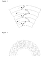
- Figures 5 and 6 show exemplary traces of articles from the center of the rotors 3 to the outer circumference where the particle exit the disintegrator 1.
- the improved device 1 according to the present invention has the similar device construction like the disintegrators 1 from the prior art [J.Durek: Disintegrator and the method for the operation thereof, US4406409 A ], [T. Lelas: Device for micronizing materials, HR990263 A2 (1999 )] shown in figures 1 and 2 .
- FIG. 5 An embodiment of a blade design (design of the hitting elements) according to the present invention is shown in figures 5 to 11 .
- a first ring 9 of trapezoidal blades carries hitting elements 5 with rectangular footprint and thus ob generally cubic shape.
- Another ring 11, directly adjoining the first ring 9 carries triangular hitting elements 7 with a footprint of a right angled triangle. These triangular hitting elements 7 are tightly positioned and of generally prismatic shape.
- the different footprints of the blades 5, 7 are shown in figure 5 .
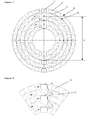
- Figure 5 shows a cross-section in the plane of rotation of the hitting elements 5, 7 thus depicting the different footprints of the hitting elements 5, 7 on the different rotors 3.
- the rotor 3 rotating in clockwise manner carries tree rings 9 of trapezoidal hitting elements 5 with rectangular footprint.
- the other rotor 3 (in the depicted view rotating counterclockwise) carries two rings 11 of triangular hitting elements 7 with triangular footprint.
- the rings 9, 11 of hitting elements 5, 7 engage alternately thus on a ring 9 rotating in clockwise manner follows a ring 11 rotating in opposite direction, i.e. counterclockwise manner.
- the present embodiment provides an elongated time of the particles within the disintegrator 1 and thus a enlarged number of inter particle collisions, permanent milling between the hitting elements 5, 7 of adjacent rings 9, 11 and a enlarged number of collisions between particles and the hitting elements 5, 7.
- the trace of a particle being micronized in a disintegrator 1 according to the present embodiment is depicted in figure 8 . Due to the arrangement of the hitting elements 5, 7 the particles move in a loope-like manner thus resulting in a prolonged time within the disintegrator 1.
- Figure 9 shows an enlarged cross-section of a triangular hitting element 7 according to the present embodiment.
- the hitting element 7 is of basically triangular footprint with rounded edges. As depicted in figure 9 the footprint is in the shape of a right angled triangle.
- the hypotenuse 15 of the right angled triangle is oriented tangentially to the outward circumference of the ring 11 built by the hitting elements 7 of it's respective ring.11
- the arrow in figure 9 indicates the direction of rotation ⁇ of the respective hitting element 7, the longer cathetus 13 of the right enabled triangle thus being forward oriented.
- a center of the hypotenuse 15 of the triangular shaped footprint is perpendicularly cut by a radius r of the respective ring 11.
- the longer cathetus 13 thus is inclined relative to the radius r by an angle ⁇ of 60 degrees.
- the other cathetus 14 is inclined relative to the radius r by an angle ⁇ of minus 30 degrees.
- Figure 11 depicts two triangular hitting elements 7 arranged in a ring like manner.
- the hitting elements 7 are spaced from one another by a distance A of 15 - 100% of the length of the hitting elements 7.
- the longest side of the rectangular hitting elements 5 for example may be 30 mm. Accordingly the longer cathetus 13 of the triangular hitting elements 7 may be of the same length.
- the course of the micronization process in the device 1 according to the present embodiment is actually the same as in the micronizer with hitting elements as disclosed in the prior art (shown in Figures 3 and 4 ).
- Material being micronized is added in the hopper 24 of the filler 23. The latter brings the material into a central part of rotating discs 3 beside their axes. Due to a strong centrifugal force, particles of material being micronized pass through two or several layers of rotating hitting elements 5, 7 (blades) of opposite discs rotating at high speed (about 5000 - 8000 rounds per minute) in opposite direction.
- the micronization device was equipped with two identical 20 kW power electro-motors that work at 220 V and 50 Hz.
- the reason why zeolite is chosen is due to its NH 4 + sorption and retention capacity. It has been already demonstrated that zeolite can have significant improvement in sorption capacity, if micronized below one ⁇ m.
- Table 1 shows the influence of the various shapes of hitting elements (blades) from different micronizing discs ( Figures 5, 6 and 8 ) on efficacy of micronization of zeolite clinoptilolite of starting particle size 50-100 ⁇ m. The goal was to achieve larger amount of submicron particles.
- Table 2 shows the influence of the various shapes of hitting elements from different micronizing discs ( Figures 5, 6 and 8 ) on particle specific surface are of zeolite clinoptilolite of starting particle specific surface area 0.9 m 2 /g.
- Table 3 shows the influence of the various shapes of hitting elements from different micronizing discs ( Figures 5, 6 and 8 ) on NH4+ sorption of zeolite clinoptilolite of starting capacity 0,23 mmol/g Table 3 MICRONIZATION-1 MICRONIZATION-2 MICRONIZATION-3 NH 4 + Sorption Capacity mmol/g 0.48 0.78 0.94
- micronized samples were analyzed for particle size (Malvern MasterSizer 2000), while the extent of crystalline disorder of particles was quantified with isothermal calorimetry (IC TAM 3, TA instruments, USA). Data was recorded with proprietary software Digitam 4.2.
- Table 4 shows the influence of the various shapes of hitting elements of different micronizing discs ( Figures 5, 6 and 8 ) on ursolic acid particle size after five repeated micronization procedures.
- Table 4 MICRONIZATION-1 MICRONIZATION-2 MICRONIZATION-3 Particles size ( ⁇ m) Volume (%) under Volume (%) under Volume (%) under 0.105 0.00 0.00 0.00 0.120 0.00 0.00 0.138 0.00 0.00 0.00 0.158 0.00 0.00 0.28 0.182 0.00 0.00 1.38 0.209 0.00 0.12 2.73 0.240 0.00 0.46 3.69 0.275 0.01 1.19 5.39 0.316 0.06 1.97 8.42 0.363 0.23 2.83 11.76 0.417 0.50 4.09 14.01 0.479 0.87 5.36 19.32 0.550 1.12 7.01 25.19 0.631 2.02 9.13 31.12 0.724 3.29 11.51 36.14 0.832 4.78 13.61 42.72 0.955 6.12 16.29 50.02 1.096 8.44 19.17 59.80
- Table 5 shows the influence of the various shapes of hitting elements from different micronizing discs ( Figures 3, 4 and 5 ) on amorphous content of ursolic acid after five repeated micronization procedures.
- Table 5 MICRONIZATION-1 MICRONIZATION-2 MICRONIZATION-3 Amorphous Content (%, w/w) 3.68 6.12 19.23
- the discs and hitting elements from the micronization device of the present invention can be built from various materials such as stainless steel 316, tungsten carbide or similar depending on the hardness of the materials to be micronized.
- the micronization device of the present invention can be successfully used for milling of pure substances or mixtures of several substances, organic, inorganic or mixed compositions. Specifically it can be used for the processing of substances from the classes of raw materials, intermediates or final products in pharmaceutical, cosmetic, food, agrochemical or construction industry, in various kinds of chemical industries, agriculture, and in other fields of production.
- a micronization process could induce defects in the crystalline network: these defects and increase of amorphous surface can improve the dissolubility of poorly soluble drugs.
- poorly soluble drugs For example one such pharmaceutically active poorly soluble substance, is anti-ursodeoxycholic acid (UDCA).
- UDCA's solubility can be significantly improved by the use of the present device in a cost effective way, thus achieving better oral bioavailability.
- the present invention can potentially enhance qualitative characteristics of various food ingredients, enabling cost-effective production processes and avoiding the need for chemical interventions.
- Micronizing macromolecular compounds can result in their more efficient processing, better solubility and oral bioavailability.
- modified molecules positively influence taste and nutritive characteristics.
- Micronized polysaccharides with high molecular mass can also improve gelling characteristic and stability of gelatinous substances. Ratio of soluble fibers in food can be also increased by application of the present invention (breakage of chains, surface area increase) which is otherwise established only by addition of enzymes and implementation of heating process.
- the prior use of the present device on those substances can significantly improve related extraction time/quality and reduce the need for organic solvents due to smaller raw material particle size, increase of specific surface (better contact of solvent and raw material) and breakage of the bonds between active ingredient and raw material.
- the present device can be also used for cost-effective processing of silica (including desert sand) to achieve more reactive nano size particles that can be used as advanced concrete additive for improvement of concrete properties or as added in certain percentage for brick production.
- silica including desert sand
- Such prepared samples of micronized Pterostilbene were subjected to particles size analyses and water solubility measurement. Average particle size after seven repeated processes of micronization were around 0.4 ⁇ m and significantly increased amorphous surface ratio (34% w/W). Solubility increased from 23 ⁇ g/ml, to 128 ⁇ g/ml.
Landscapes
- Engineering & Computer Science (AREA)
- Food Science & Technology (AREA)
- Crushing And Pulverization Processes (AREA)
- Crushing And Grinding (AREA)
Priority Applications (2)
| Application Number | Priority Date | Filing Date | Title |
|---|---|---|---|
| DK12177709.8T DK2689855T3 (en) | 2012-07-24 | 2012-07-24 | Mikroniseringsindretning modified, and the use thereof |
| EP12177709.8A EP2689855B1 (de) | 2012-07-24 | 2012-07-24 | Modifizierte Mikronisierungsvorrichtung und ihre Verwendung |
Applications Claiming Priority (1)
| Application Number | Priority Date | Filing Date | Title |
|---|---|---|---|
| EP12177709.8A EP2689855B1 (de) | 2012-07-24 | 2012-07-24 | Modifizierte Mikronisierungsvorrichtung und ihre Verwendung |
Publications (2)
| Publication Number | Publication Date |
|---|---|
| EP2689855A1 true EP2689855A1 (de) | 2014-01-29 |
| EP2689855B1 EP2689855B1 (de) | 2015-07-01 |
Family
ID=46679120
Family Applications (1)
| Application Number | Title | Priority Date | Filing Date |
|---|---|---|---|
| EP12177709.8A Active EP2689855B1 (de) | 2012-07-24 | 2012-07-24 | Modifizierte Mikronisierungsvorrichtung und ihre Verwendung |
Country Status (2)
| Country | Link |
|---|---|
| EP (1) | EP2689855B1 (de) |
| DK (1) | DK2689855T3 (de) |
Cited By (4)
| Publication number | Priority date | Publication date | Assignee | Title |
|---|---|---|---|---|
| RU2563693C1 (ru) * | 2014-07-08 | 2015-09-20 | Федеральное государственное бюджетное образовательное учреждение высшего профессионального образования "Белгородский государственный технологический университет им. В.Г. Шухова" | Дезинтегратор |
| WO2018121803A1 (en) | 2016-12-28 | 2018-07-05 | Houdek Jan | Device and method for micronization of solid materials |
| JP2020510531A (ja) * | 2017-02-24 | 2020-04-09 | グリーンボルト ナノ インコーポレイテッドGreenvolt Nano Inc. | ナノ粒子を形成するための装置及び方法 |
| US11607693B2 (en) | 2017-02-24 | 2023-03-21 | Nanom Inc. | Apparatus and method for forming nanoparticles |
Citations (3)
| Publication number | Priority date | Publication date | Assignee | Title |
|---|---|---|---|---|
| US4406409A (en) | 1980-09-16 | 1983-09-27 | Joachim Durek | Disintegrator and method for the operation thereof |
| HRP990263A2 (hr) | 1999-04-26 | 2009-04-30 | Lelas Tihomir | Uređaj za mikroniziranje materijala |
| WO2012025770A2 (en) * | 2010-08-23 | 2012-03-01 | Creogen D.O.O. | Device for micronization of solid materials and its use |
-
2012
- 2012-07-24 EP EP12177709.8A patent/EP2689855B1/de active Active
- 2012-07-24 DK DK12177709.8T patent/DK2689855T3/en active
Patent Citations (3)
| Publication number | Priority date | Publication date | Assignee | Title |
|---|---|---|---|---|
| US4406409A (en) | 1980-09-16 | 1983-09-27 | Joachim Durek | Disintegrator and method for the operation thereof |
| HRP990263A2 (hr) | 1999-04-26 | 2009-04-30 | Lelas Tihomir | Uređaj za mikroniziranje materijala |
| WO2012025770A2 (en) * | 2010-08-23 | 2012-03-01 | Creogen D.O.O. | Device for micronization of solid materials and its use |
Cited By (5)
| Publication number | Priority date | Publication date | Assignee | Title |
|---|---|---|---|---|
| RU2563693C1 (ru) * | 2014-07-08 | 2015-09-20 | Федеральное государственное бюджетное образовательное учреждение высшего профессионального образования "Белгородский государственный технологический университет им. В.Г. Шухова" | Дезинтегратор |
| WO2018121803A1 (en) | 2016-12-28 | 2018-07-05 | Houdek Jan | Device and method for micronization of solid materials |
| JP2020510531A (ja) * | 2017-02-24 | 2020-04-09 | グリーンボルト ナノ インコーポレイテッドGreenvolt Nano Inc. | ナノ粒子を形成するための装置及び方法 |
| JP2023022008A (ja) * | 2017-02-24 | 2023-02-14 | ナノム インコーポレイテッド | ナノ粒子を形成するための装置及び方法 |
| US11607693B2 (en) | 2017-02-24 | 2023-03-21 | Nanom Inc. | Apparatus and method for forming nanoparticles |
Also Published As
| Publication number | Publication date |
|---|---|
| EP2689855B1 (de) | 2015-07-01 |
| DK2689855T3 (en) | 2015-10-12 |
Similar Documents
| Publication | Publication Date | Title |
|---|---|---|
| CN103167912B (zh) | 用于微粉化固体材料的设备 | |
| EP2689855B1 (de) | Modifizierte Mikronisierungsvorrichtung und ihre Verwendung | |
| JPS5915699B2 (ja) | 湿式粉砕装置 | |
| CA1331875C (en) | Mill for pulverizing rock and other material | |
| CN100484635C (zh) | 微粉冲击磨机及其粉体加工系统 | |
| US7631826B2 (en) | Crushing apparatus | |
| US20150209794A1 (en) | Modified micronization device and method thereof | |
| EP0756896A1 (de) | Vorrichtung zum Pulverisieren von Kohle | |
| US20240254660A1 (en) | Configurable apparatus and methods for decorticating, comminuting, and liberating fibers and hurd from hemp stalks and related materials using selective differential fragmentation | |
| KR100470285B1 (ko) | 기계식 분쇄기 | |
| JP2010537813A (ja) | 粉砕ミル及び粉砕方法 | |
| CN207238082U (zh) | 一种药材粉碎装置 | |
| CN204816676U (zh) | 一种磨粉机 | |
| RU2166367C1 (ru) | Способ и устройство для измельчения материалов | |
| US7207513B2 (en) | Device and method for comminuting materials | |
| US20070040055A1 (en) | Method and apparatus for pulverizing solid materials | |
| CN107597354A (zh) | 一种高效气流粉碎机 | |
| CN207805744U (zh) | 一种高效气流粉碎机 | |
| EP3393669B1 (de) | Vorrichtung und verfahren zur mikronisierung von feststoffen | |
| JP2004330072A (ja) | 乾式粉砕装置 | |
| WO2012025770A2 (en) | Device for micronization of solid materials and its use | |
| JP2006175323A (ja) | 遠心破砕機 | |
| RU2618691C1 (ru) | Дезинтегратор | |
| EP1177045B1 (de) | Verfahren und vorrichtung zum steuern eines materialflusses in einer vorgegebenen bahn | |
| JPWO2000059641A1 (ja) | 粉流体の極微細化装置および極微細化方法 |
Legal Events
| Date | Code | Title | Description |
|---|---|---|---|
| PUAI | Public reference made under article 153(3) epc to a published international application that has entered the european phase |
Free format text: ORIGINAL CODE: 0009012 |
|
| AK | Designated contracting states |
Kind code of ref document: A1 Designated state(s): AL AT BE BG CH CY CZ DE DK EE ES FI FR GB GR HR HU IE IS IT LI LT LU LV MC MK MT NL NO PL PT RO RS SE SI SK SM TR |
|
| AX | Request for extension of the european patent |
Extension state: BA ME |
|
| 17P | Request for examination filed |
Effective date: 20140725 |
|
| RBV | Designated contracting states (corrected) |
Designated state(s): AL AT BE BG CH CY CZ DE DK EE ES FI FR GB GR HR HU IE IS IT LI LT LU LV MC MK MT NL NO PL PT RO RS SE SI SK SM TR |
|
| RIC1 | Information provided on ipc code assigned before grant |
Ipc: B02C 13/22 20060101AFI20141110BHEP |
|
| GRAP | Despatch of communication of intention to grant a patent |
Free format text: ORIGINAL CODE: EPIDOSNIGR1 |
|
| INTG | Intention to grant announced |
Effective date: 20150107 |
|
| GRAS | Grant fee paid |
Free format text: ORIGINAL CODE: EPIDOSNIGR3 |
|
| GRAA | (expected) grant |
Free format text: ORIGINAL CODE: 0009210 |
|
| AK | Designated contracting states |
Kind code of ref document: B1 Designated state(s): AL AT BE BG CH CY CZ DE DK EE ES FI FR GB GR HR HU IE IS IT LI LT LU LV MC MK MT NL NO PL PT RO RS SE SI SK SM TR |
|
| REG | Reference to a national code |
Ref country code: GB Ref legal event code: FG4D |
|
| REG | Reference to a national code |
Ref country code: AT Ref legal event code: REF Ref document number: 733626 Country of ref document: AT Kind code of ref document: T Effective date: 20150715 Ref country code: CH Ref legal event code: EP |
|
| REG | Reference to a national code |
Ref country code: IE Ref legal event code: FG4D |
|
| REG | Reference to a national code |
Ref country code: DE Ref legal event code: R096 Ref document number: 602012008326 Country of ref document: DE |
|
| REG | Reference to a national code |
Ref country code: DK Ref legal event code: T3 Effective date: 20151005 |
|
| REG | Reference to a national code |
Ref country code: CH Ref legal event code: NV Representative=s name: R.A. EGLI AND CO, PATENTANWAELTE, CH |
|
| REG | Reference to a national code |
Ref country code: AT Ref legal event code: MK05 Ref document number: 733626 Country of ref document: AT Kind code of ref document: T Effective date: 20150701 |
|
| REG | Reference to a national code |
Ref country code: NO Ref legal event code: T2 Effective date: 20150701 |
|
| REG | Reference to a national code |
Ref country code: NL Ref legal event code: MP Effective date: 20150701 |
|
| REG | Reference to a national code |
Ref country code: LT Ref legal event code: MG4D |
|
| REG | Reference to a national code |
Ref country code: FR Ref legal event code: PLFP Year of fee payment: 4 |
|
| PG25 | Lapsed in a contracting state [announced via postgrant information from national office to epo] |
Ref country code: LV Free format text: LAPSE BECAUSE OF FAILURE TO SUBMIT A TRANSLATION OF THE DESCRIPTION OR TO PAY THE FEE WITHIN THE PRESCRIBED TIME-LIMIT Effective date: 20150701 Ref country code: GR Free format text: LAPSE BECAUSE OF FAILURE TO SUBMIT A TRANSLATION OF THE DESCRIPTION OR TO PAY THE FEE WITHIN THE PRESCRIBED TIME-LIMIT Effective date: 20151002 Ref country code: LT Free format text: LAPSE BECAUSE OF FAILURE TO SUBMIT A TRANSLATION OF THE DESCRIPTION OR TO PAY THE FEE WITHIN THE PRESCRIBED TIME-LIMIT Effective date: 20150701 Ref country code: FI Free format text: LAPSE BECAUSE OF FAILURE TO SUBMIT A TRANSLATION OF THE DESCRIPTION OR TO PAY THE FEE WITHIN THE PRESCRIBED TIME-LIMIT Effective date: 20150701 |
|
| PG25 | Lapsed in a contracting state [announced via postgrant information from national office to epo] |
Ref country code: AT Free format text: LAPSE BECAUSE OF FAILURE TO SUBMIT A TRANSLATION OF THE DESCRIPTION OR TO PAY THE FEE WITHIN THE PRESCRIBED TIME-LIMIT Effective date: 20150701 Ref country code: HR Free format text: LAPSE BECAUSE OF FAILURE TO SUBMIT A TRANSLATION OF THE DESCRIPTION OR TO PAY THE FEE WITHIN THE PRESCRIBED TIME-LIMIT Effective date: 20150701 Ref country code: PL Free format text: LAPSE BECAUSE OF FAILURE TO SUBMIT A TRANSLATION OF THE DESCRIPTION OR TO PAY THE FEE WITHIN THE PRESCRIBED TIME-LIMIT Effective date: 20150701 Ref country code: PT Free format text: LAPSE BECAUSE OF FAILURE TO SUBMIT A TRANSLATION OF THE DESCRIPTION OR TO PAY THE FEE WITHIN THE PRESCRIBED TIME-LIMIT Effective date: 20151102 Ref country code: SE Free format text: LAPSE BECAUSE OF FAILURE TO SUBMIT A TRANSLATION OF THE DESCRIPTION OR TO PAY THE FEE WITHIN THE PRESCRIBED TIME-LIMIT Effective date: 20150701 Ref country code: IS Free format text: LAPSE BECAUSE OF FAILURE TO SUBMIT A TRANSLATION OF THE DESCRIPTION OR TO PAY THE FEE WITHIN THE PRESCRIBED TIME-LIMIT Effective date: 20151101 Ref country code: ES Free format text: LAPSE BECAUSE OF FAILURE TO SUBMIT A TRANSLATION OF THE DESCRIPTION OR TO PAY THE FEE WITHIN THE PRESCRIBED TIME-LIMIT Effective date: 20150701 Ref country code: RS Free format text: LAPSE BECAUSE OF FAILURE TO SUBMIT A TRANSLATION OF THE DESCRIPTION OR TO PAY THE FEE WITHIN THE PRESCRIBED TIME-LIMIT Effective date: 20150701 |
|
| PG25 | Lapsed in a contracting state [announced via postgrant information from national office to epo] |
Ref country code: MC Free format text: LAPSE BECAUSE OF FAILURE TO SUBMIT A TRANSLATION OF THE DESCRIPTION OR TO PAY THE FEE WITHIN THE PRESCRIBED TIME-LIMIT Effective date: 20150701 |
|
| REG | Reference to a national code |
Ref country code: DE Ref legal event code: R097 Ref document number: 602012008326 Country of ref document: DE |
|
| REG | Reference to a national code |
Ref country code: IE Ref legal event code: MM4A |
|
| PG25 | Lapsed in a contracting state [announced via postgrant information from national office to epo] |
Ref country code: IT Free format text: LAPSE BECAUSE OF FAILURE TO SUBMIT A TRANSLATION OF THE DESCRIPTION OR TO PAY THE FEE WITHIN THE PRESCRIBED TIME-LIMIT Effective date: 20150701 Ref country code: CZ Free format text: LAPSE BECAUSE OF FAILURE TO SUBMIT A TRANSLATION OF THE DESCRIPTION OR TO PAY THE FEE WITHIN THE PRESCRIBED TIME-LIMIT Effective date: 20150701 Ref country code: SK Free format text: LAPSE BECAUSE OF FAILURE TO SUBMIT A TRANSLATION OF THE DESCRIPTION OR TO PAY THE FEE WITHIN THE PRESCRIBED TIME-LIMIT Effective date: 20150701 Ref country code: EE Free format text: LAPSE BECAUSE OF FAILURE TO SUBMIT A TRANSLATION OF THE DESCRIPTION OR TO PAY THE FEE WITHIN THE PRESCRIBED TIME-LIMIT Effective date: 20150701 |
|
| PLBE | No opposition filed within time limit |
Free format text: ORIGINAL CODE: 0009261 |
|
| STAA | Information on the status of an ep patent application or granted ep patent |
Free format text: STATUS: NO OPPOSITION FILED WITHIN TIME LIMIT |
|
| PG25 | Lapsed in a contracting state [announced via postgrant information from national office to epo] |
Ref country code: RO Free format text: LAPSE BECAUSE OF FAILURE TO SUBMIT A TRANSLATION OF THE DESCRIPTION OR TO PAY THE FEE WITHIN THE PRESCRIBED TIME-LIMIT Effective date: 20150701 |
|
| 26N | No opposition filed |
Effective date: 20160404 |
|
| REG | Reference to a national code |
Ref country code: FR Ref legal event code: PLFP Year of fee payment: 5 |
|
| PG25 | Lapsed in a contracting state [announced via postgrant information from national office to epo] |
Ref country code: IE Free format text: LAPSE BECAUSE OF NON-PAYMENT OF DUE FEES Effective date: 20150724 |
|
| PG25 | Lapsed in a contracting state [announced via postgrant information from national office to epo] |
Ref country code: SI Free format text: LAPSE BECAUSE OF FAILURE TO SUBMIT A TRANSLATION OF THE DESCRIPTION OR TO PAY THE FEE WITHIN THE PRESCRIBED TIME-LIMIT Effective date: 20150701 |
|
| PG25 | Lapsed in a contracting state [announced via postgrant information from national office to epo] |
Ref country code: BE Free format text: LAPSE BECAUSE OF FAILURE TO SUBMIT A TRANSLATION OF THE DESCRIPTION OR TO PAY THE FEE WITHIN THE PRESCRIBED TIME-LIMIT Effective date: 20150701 |
|
| PG25 | Lapsed in a contracting state [announced via postgrant information from national office to epo] |
Ref country code: MT Free format text: LAPSE BECAUSE OF FAILURE TO SUBMIT A TRANSLATION OF THE DESCRIPTION OR TO PAY THE FEE WITHIN THE PRESCRIBED TIME-LIMIT Effective date: 20150701 |
|
| PG25 | Lapsed in a contracting state [announced via postgrant information from national office to epo] |
Ref country code: BG Free format text: LAPSE BECAUSE OF FAILURE TO SUBMIT A TRANSLATION OF THE DESCRIPTION OR TO PAY THE FEE WITHIN THE PRESCRIBED TIME-LIMIT Effective date: 20150701 Ref country code: HU Free format text: LAPSE BECAUSE OF FAILURE TO SUBMIT A TRANSLATION OF THE DESCRIPTION OR TO PAY THE FEE WITHIN THE PRESCRIBED TIME-LIMIT; INVALID AB INITIO Effective date: 20120724 Ref country code: SM Free format text: LAPSE BECAUSE OF FAILURE TO SUBMIT A TRANSLATION OF THE DESCRIPTION OR TO PAY THE FEE WITHIN THE PRESCRIBED TIME-LIMIT Effective date: 20150701 |
|
| PG25 | Lapsed in a contracting state [announced via postgrant information from national office to epo] |
Ref country code: CY Free format text: LAPSE BECAUSE OF FAILURE TO SUBMIT A TRANSLATION OF THE DESCRIPTION OR TO PAY THE FEE WITHIN THE PRESCRIBED TIME-LIMIT Effective date: 20150701 Ref country code: NL Free format text: LAPSE BECAUSE OF FAILURE TO SUBMIT A TRANSLATION OF THE DESCRIPTION OR TO PAY THE FEE WITHIN THE PRESCRIBED TIME-LIMIT Effective date: 20150701 |
|
| REG | Reference to a national code |
Ref country code: FR Ref legal event code: PLFP Year of fee payment: 6 |
|
| PG25 | Lapsed in a contracting state [announced via postgrant information from national office to epo] |
Ref country code: LU Free format text: LAPSE BECAUSE OF NON-PAYMENT OF DUE FEES Effective date: 20150724 |
|
| PG25 | Lapsed in a contracting state [announced via postgrant information from national office to epo] |
Ref country code: MK Free format text: LAPSE BECAUSE OF FAILURE TO SUBMIT A TRANSLATION OF THE DESCRIPTION OR TO PAY THE FEE WITHIN THE PRESCRIBED TIME-LIMIT Effective date: 20150701 Ref country code: TR Free format text: LAPSE BECAUSE OF FAILURE TO SUBMIT A TRANSLATION OF THE DESCRIPTION OR TO PAY THE FEE WITHIN THE PRESCRIBED TIME-LIMIT Effective date: 20150701 |
|
| REG | Reference to a national code |
Ref country code: FR Ref legal event code: PLFP Year of fee payment: 7 |
|
| PG25 | Lapsed in a contracting state [announced via postgrant information from national office to epo] |
Ref country code: AL Free format text: LAPSE BECAUSE OF FAILURE TO SUBMIT A TRANSLATION OF THE DESCRIPTION OR TO PAY THE FEE WITHIN THE PRESCRIBED TIME-LIMIT Effective date: 20150701 |
|
| REG | Reference to a national code |
Ref country code: DE Ref legal event code: R082 Ref document number: 602012008326 Country of ref document: DE Representative=s name: JANNIG & REPKOW PATENTANWAELTE PARTG MBB, DE Ref country code: DE Ref legal event code: R081 Ref document number: 602012008326 Country of ref document: DE Owner name: LELAS, ANTONIO, HR Free format text: FORMER OWNER: OEKOMINERAL AG, BRUGG, CH |
|
| PGFP | Annual fee paid to national office [announced via postgrant information from national office to epo] |
Ref country code: NO Payment date: 20200723 Year of fee payment: 9 |
|
| PGFP | Annual fee paid to national office [announced via postgrant information from national office to epo] |
Ref country code: DK Payment date: 20211021 Year of fee payment: 10 Ref country code: GB Payment date: 20211015 Year of fee payment: 10 |
|
| PGFP | Annual fee paid to national office [announced via postgrant information from national office to epo] |
Ref country code: FR Payment date: 20211018 Year of fee payment: 10 Ref country code: CH Payment date: 20211022 Year of fee payment: 10 |
|
| REG | Reference to a national code |
Ref country code: NO Ref legal event code: MMEP |
|
| PG25 | Lapsed in a contracting state [announced via postgrant information from national office to epo] |
Ref country code: NO Free format text: LAPSE BECAUSE OF NON-PAYMENT OF DUE FEES Effective date: 20210731 |
|
| REG | Reference to a national code |
Ref country code: DK Ref legal event code: EBP Effective date: 20220731 |
|
| REG | Reference to a national code |
Ref country code: CH Ref legal event code: PL |
|
| GBPC | Gb: european patent ceased through non-payment of renewal fee |
Effective date: 20220724 |
|
| PG25 | Lapsed in a contracting state [announced via postgrant information from national office to epo] |
Ref country code: LI Free format text: LAPSE BECAUSE OF NON-PAYMENT OF DUE FEES Effective date: 20220731 Ref country code: FR Free format text: LAPSE BECAUSE OF NON-PAYMENT OF DUE FEES Effective date: 20220731 Ref country code: CH Free format text: LAPSE BECAUSE OF NON-PAYMENT OF DUE FEES Effective date: 20220731 |
|
| PG25 | Lapsed in a contracting state [announced via postgrant information from national office to epo] |
Ref country code: GB Free format text: LAPSE BECAUSE OF NON-PAYMENT OF DUE FEES Effective date: 20220724 |
|
| PG25 | Lapsed in a contracting state [announced via postgrant information from national office to epo] |
Ref country code: DK Free format text: LAPSE BECAUSE OF NON-PAYMENT OF DUE FEES Effective date: 20220731 |
|
| PGFP | Annual fee paid to national office [announced via postgrant information from national office to epo] |
Ref country code: DE Payment date: 20240904 Year of fee payment: 13 |