EP2689896B1 - Elektrowerkzeug - Google Patents
Elektrowerkzeug Download PDFInfo
- Publication number
- EP2689896B1 EP2689896B1 EP12760058.3A EP12760058A EP2689896B1 EP 2689896 B1 EP2689896 B1 EP 2689896B1 EP 12760058 A EP12760058 A EP 12760058A EP 2689896 B1 EP2689896 B1 EP 2689896B1
- Authority
- EP
- European Patent Office
- Prior art keywords
- motor
- control means
- condition
- switch
- deactivation state
- Prior art date
- Legal status (The legal status is an assumption and is not a legal conclusion. Google has not performed a legal analysis and makes no representation as to the accuracy of the status listed.)
- Active
Links
Images
Classifications
-
- B—PERFORMING OPERATIONS; TRANSPORTING
- B25—HAND TOOLS; PORTABLE POWER-DRIVEN TOOLS; MANIPULATORS
- B25F—COMBINATION OR MULTI-PURPOSE TOOLS NOT OTHERWISE PROVIDED FOR; DETAILS OR COMPONENTS OF PORTABLE POWER-DRIVEN TOOLS NOT PARTICULARLY RELATED TO THE OPERATIONS PERFORMED AND NOT OTHERWISE PROVIDED FOR
- B25F5/00—Details or components of portable power-driven tools not particularly related to the operations performed and not otherwise provided for
-
- B—PERFORMING OPERATIONS; TRANSPORTING
- B05—SPRAYING OR ATOMISING IN GENERAL; APPLYING FLUENT MATERIALS TO SURFACES, IN GENERAL
- B05C—APPARATUS FOR APPLYING FLUENT MATERIALS TO SURFACES, IN GENERAL
- B05C17/00—Hand tools or apparatus using hand held tools, for applying liquids or other fluent materials to, for spreading applied liquids or other fluent materials on, or for partially removing applied liquids or other fluent materials from, surfaces
- B05C17/005—Hand tools or apparatus using hand held tools, for applying liquids or other fluent materials to, for spreading applied liquids or other fluent materials on, or for partially removing applied liquids or other fluent materials from, surfaces for discharging material from a reservoir or container located in or on the hand tool through an outlet orifice by pressure without using surface contacting members like pads or brushes
- B05C17/01—Hand tools or apparatus using hand held tools, for applying liquids or other fluent materials to, for spreading applied liquids or other fluent materials on, or for partially removing applied liquids or other fluent materials from, surfaces for discharging material from a reservoir or container located in or on the hand tool through an outlet orifice by pressure without using surface contacting members like pads or brushes with manually mechanically or electrically actuated piston or the like
- B05C17/0103—Hand tools or apparatus using hand held tools, for applying liquids or other fluent materials to, for spreading applied liquids or other fluent materials on, or for partially removing applied liquids or other fluent materials from, surfaces for discharging material from a reservoir or container located in or on the hand tool through an outlet orifice by pressure without using surface contacting members like pads or brushes with manually mechanically or electrically actuated piston or the like with electrically actuated piston or the like
-
- H—ELECTRICITY
- H02—GENERATION; CONVERSION OR DISTRIBUTION OF ELECTRIC POWER
- H02H—EMERGENCY PROTECTIVE CIRCUIT ARRANGEMENTS
- H02H7/00—Emergency protective circuit arrangements specially adapted for specific types of electric machines or apparatus or for sectionalised protection of cable or line systems, and effecting automatic switching in the event of an undesired change from normal working conditions
- H02H7/08—Emergency protective circuit arrangements specially adapted for specific types of electric machines or apparatus or for sectionalised protection of cable or line systems, and effecting automatic switching in the event of an undesired change from normal working conditions for dynamo-electric motors
- H02H7/085—Emergency protective circuit arrangements specially adapted for specific types of electric machines or apparatus or for sectionalised protection of cable or line systems, and effecting automatic switching in the event of an undesired change from normal working conditions for dynamo-electric motors against excessive load
-
- H—ELECTRICITY
- H02—GENERATION; CONVERSION OR DISTRIBUTION OF ELECTRIC POWER
- H02J—ELECTRIC POWER NETWORKS; CIRCUIT ARRANGEMENTS OR SYSTEMS FOR SUPPLYING OR DISTRIBUTING ELECTRIC POWER; SYSTEMS FOR STORING ELECTRIC ENERGY
- H02J7/00—Circuit arrangements for charging or discharging batteries or for supplying loads from batteries
- H02J7/855—Circuit arrangements for charging or discharging batteries or for supplying loads from batteries with circuits adapted for supplying loads from the battery
-
- H—ELECTRICITY
- H02—GENERATION; CONVERSION OR DISTRIBUTION OF ELECTRIC POWER
- H02J—ELECTRIC POWER NETWORKS; CIRCUIT ARRANGEMENTS OR SYSTEMS FOR SUPPLYING OR DISTRIBUTING ELECTRIC POWER; SYSTEMS FOR STORING ELECTRIC ENERGY
- H02J7/00—Circuit arrangements for charging or discharging batteries or for supplying loads from batteries
- H02J7/90—Regulation of charging or discharging current or voltage
- H02J7/94—Regulation of charging or discharging current or voltage in response to battery current
-
- H—ELECTRICITY
- H01—ELECTRIC ELEMENTS
- H01M—PROCESSES OR MEANS, e.g. BATTERIES, FOR THE DIRECT CONVERSION OF CHEMICAL ENERGY INTO ELECTRICAL ENERGY
- H01M10/00—Secondary cells; Manufacture thereof
- H01M10/42—Methods or arrangements for servicing or maintenance of secondary cells or secondary half-cells
- H01M10/425—Structural combination with electronic components, e.g. electronic circuits integrated to the outside of the casing
- H01M10/4257—Smart batteries, e.g. electronic circuits inside the housing of the cells or batteries
-
- H—ELECTRICITY
- H02—GENERATION; CONVERSION OR DISTRIBUTION OF ELECTRIC POWER
- H02J—ELECTRIC POWER NETWORKS; CIRCUIT ARRANGEMENTS OR SYSTEMS FOR SUPPLYING OR DISTRIBUTING ELECTRIC POWER; SYSTEMS FOR STORING ELECTRIC ENERGY
- H02J7/00—Circuit arrangements for charging or discharging batteries or for supplying loads from batteries
- H02J7/60—Circuit arrangements for charging or discharging batteries or for supplying loads from batteries including safety or protection arrangements
- H02J7/62—Circuit arrangements for charging or discharging batteries or for supplying loads from batteries including safety or protection arrangements against overcurrent
-
- Y—GENERAL TAGGING OF NEW TECHNOLOGICAL DEVELOPMENTS; GENERAL TAGGING OF CROSS-SECTIONAL TECHNOLOGIES SPANNING OVER SEVERAL SECTIONS OF THE IPC; TECHNICAL SUBJECTS COVERED BY FORMER USPC CROSS-REFERENCE ART COLLECTIONS [XRACs] AND DIGESTS
- Y02—TECHNOLOGIES OR APPLICATIONS FOR MITIGATION OR ADAPTATION AGAINST CLIMATE CHANGE
- Y02E—REDUCTION OF GREENHOUSE GAS [GHG] EMISSIONS, RELATED TO ENERGY GENERATION, TRANSMISSION OR DISTRIBUTION
- Y02E60/00—Enabling technologies; Technologies with a potential or indirect contribution to GHG emissions mitigation
- Y02E60/10—Energy storage using batteries
Definitions
- the invention relates to an electric tool that is configured to forcibly deactivate a motor when an electric current exceeds a threshold.
- Japanese Patent Application Publication No. H1-311887 describes such an electric tool that is configured, after forcible deactivation of a motor, to maintain this forcible deactivation while an operation switch is depressed by a user; and to cancel this forcible deactivation when the operation switch is released from being depressed (cf. also JP2001252602 and US2007/069672 ).
- the conventional electric tool described above requires to release the operation switch from being depressed by releasing one's finger therefrom, in order to cancel the forcible deactivation of the motor. Therefore, in the case of performing a work which frequently causes an excess current flowing through a motor, the user is required to release one's finger from the operation switch and then depress the operation switch again whenever the motor is forcibly deactivated. This requirement deteriorates the work efficiency.
- US 2010/0084150 A1 describes an electric power tool including a tool body and a battery pack.
- An over-current determination unit of the battery pack determines whether or not a magnitude of an electric current flowing from the battery pack to the tool body is greater than a predetermined current value. If so, a permission determination unit can be set so as not to permit supply of electric power from the battery pack to a drive portion when the magnitude of the electric current flowing from the battery pack to the tool body is greater than the predetermined current value. In this way an excessive electric current flowing from the battery pack to the tool body can be inhibited, however, this document does not disclose two cancel conditions.
- EP 1 825 964 A1 describes an electric power tool including a motor; a battery unit for supplying an electric power for driving the motor; a manipulation unit for receiving input data including a rotation number and an on/off manipulation of the motor; and a motor control unit for controlling the motor based on the input data from the manipulation unit.
- a rotation of the motor is stopped or suppressed.
- a load detector detects a load of the motor, and the motor control unit stops the motor if a load value detected by the load detector while being operated in the limited operation mode exceeds a specific reference value for a specific period of time.
- EP 2 015 421 A2 describes a reset mechanism for a battery pack.
- a battery pack may include functionality to protect against fault conditions inside and outside the battery pack.
- the battery pack may be configured to shutdown or reduce current flow when subjected to adverse conditions.
- a reset mechanism may be provided to guard against unexpected startup of a device powered by the battery pack after a shutdown event. The reset mechanism may require user interaction to ensure that resetting the battery pack after a shutdown event is done intentionally.
- the invention is developed in view of above problem, and it is an object of the invention to provide an electric tool capable of securing safety by forcibly deactivating a motor when an electric current exceeds a threshold, while suppressing deterioration of the work efficiency.
- an electric tool of the present disclosure includes: a motor as a drive source of the electric tool; a main switch for switching ON or OFF of electricity supply to the motor; a current detection means for detecting a value of a current flowing through the motor; an output adjustment switch for adjusting a rotational output of the motor; and a control means configured to forcibly deactivate the motor when a detection result by the current detection means exceeds a predetermined threshold.
- the control means has: a first cancel condition that the main switch is switched off under a forcible deactivation state; and a second cancel condition that the output adjustment switch is manipulated under the forcible deactivation state, where the forcible deactivation state is a state that the control means is set to forcibly deactivate the motor.
- the control means is configured to cancel the forcible deactivation state when the first or second cancel condition is satisfied.
- an electric tool of the present disclosure includes: a motor as a drive source of the electric tool; a main switch for switching ON or OFF of electricity supply to the motor; a current detection means for detecting a value of a current flowing through the motor; an output adjustment switch for adjusting a rotational output of the motor; and a control means configured to forcibly deactivate the motor when a detection result by the current detection means exceeds a predetermined threshold.
- the control means has: a first cancel condition that the main switch is switched off under the condition of forcibly deactivating the motor; and a second cancel condition that the output adjustment switch is manipulated under the condition of forcibly deactivating the motor.
- the control means is configured to cancel the forcible deactivation of the motor when the first or second cancel condition is satisfied.
- the main switch is configured to switch on the electricity supply to the motor according to a depressed operation
- the first cancel condition is a condition that the main switch under the forcible deactivation state is released from being depressed.
- the main switch is configured to switch on the electricity supply to the motor according to a depressed operation
- the first cancel condition is a condition that the main switch is released from being depressed under a condition where the control means forcibly deactivates the motor.
- the second cancel condition contains a condition that the output adjustment switch is manipulated more than a prescribed amount under the forcible deactivation state.
- the second cancel condition contains a condition that the output adjustment switch is manipulated more than a prescribed amount under a condition where the control means forcibly deactivates the motor.
- the second cancel condition contains a condition that the output adjustment switch is manipulated within a predetermined time from a start point of the forcible deactivation state.
- the second cancel condition contains a condition that the output adjustment switch is manipulated within a predetermined time from a point in time when the motor is deactivated by the control means.
- control means is configured to change the threshold to another threshold higher than this threshold after the forcible deactivation state is canceled as a result of the satisfaction of the second cancel condition.
- control means is configured to change the threshold to another threshold higher than this threshold after the control means canceling the forcible deactivation of the motor as a result of the satisfaction of the second cancel condition.
- the electric tool further includes a switching means for regulating a rotation of the motor.
- the control means is configured to control the switching means based on a value of the rotational output adjusted by the output adjustment switch.
- the control means is configured to turn off the switching means when a value of the current detected by the current detection means exceeds the predetermined threshold, thereby forcibly deactivating the motor.
- the invention has an effect of securing safety by forcibly deactivating a motor when an electric current exceeds a threshold, while suppressing deterioration of the work efficiency.
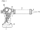
- FIG. 1 is a side view of an electric tool according to an embodiment of the invention.
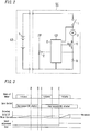
- FIG. 2 is a circuit diagram of the electric tool.
- the electric tool of the embodiment is a portable sealing gun (caulk gun) 50 that includes a main switch 1 and an output adjustment switch 2.
- the sealing gun 50 has a main body 10 shaped like a cylinder in which a motor 3 as a drive source for the tool is put.
- a handle 11 is formed to extend from the main body 10 toward outside (toward lower side in FIG. 1 ) in the radial direction.
- the handle 11 is provided with the main switch 1 of a trigger switch and the output adjustment switch 2 of a speed adjustment dial.
- the main switch 1 is constituted by a switch of a trigger type.
- the main switch 1 is configured to switch on the electricity supply to the motor 3 according to a depressed operation, and also to switch off the electricity supply to the motor 3 when it is released from being depressed.
- the main switch 1 is not limited to a switch of the trigger type, and may be a switch of a button type or a slide type.
- a barrel 5 shaped like a hollow cylinder with a nozzle 4 at a tip thereof is attached to the main body 10.
- a bar-shaped rod (not shown) is disposed within the barrel 5.
- a push member (not shown) shaped like a substantially circular plate is fixed at an end of the rod such that the push member makes a sliding contact with an inner surface of the barrel 5. The rod moves in the axial direction thereof though a drive power of the motor 3 in the main body 10, and thereby sealing agent in the barrel 5 is pushed by the push member at the tip of the rod, and is ejected through a discharge hole 4a of the tip of the nozzle 4.
- a battery pack 12 is detachably attached to an end (lower end in FIG. 1 ) of the handle 11.
- Secondary cells 7 as a power source of the sealing gun 50 are housed in the battery pack 12.
- the secondary cells 7 supply electricity to the motor 3, a control means 6, and the like in the sealing gun 50.
- the control means 6 controls a rotation of the motor 3 according to input signals from the main switch 1 and output adjustment switch 2.
- the motor 3 in a circuit for supplying electricity from the secondary cells 7 to the motor 3, the motor 3 is connected in series with: a switching means 8 constituted by an switching element of an FET; and a current detection means 9 constituted by a current detection resistor.
- the control means 6 controls electricity supply to the motor 3 by means of the switching means 8.
- the control means 6 detects a value of a current flowing through the motor 3 on the basis of a voltage induced across the current detection means 9.
- the electricity supply to the motor 3 is switched on when the main switch 1 is depressed more than a predetermined amount (i.e., when the main switch 1 is turned on).
- the electricity supply to the motor 3 is switched off when the main switch 1 is released from being depressed (i.e., when the main switch 1 is turned off).
- the control means 6 is configured to drive the switching means 8 on the basis of PWM control in which duty ratio is changed depending on a voltage value that is associated with a rotation position of the output adjustment switch 2. Rotation speed of the motor 3 is thereby adjusted.
- the control means 6 is configured to detect a value of a current flowing through the motor 3 by the current detection means 9.
- the control means 6 is configured to forcibly deactivate the motor 3 by turning off the switching means 8 when a detected result (detected current) exceeds a predetermined threshold even with the main switch 1 depressed.
- the threshold changes depending on a rotation position of the dial (i.e., set value of motor output) of the output adjustment switch 2.
- the control means 6 may include a threshold table in which set values of motor output (selectable by the output adjustment switch 2) are associated with respective thresholds (thresholds compared with the detected current) for forcibly deactivating the motor 3.
- control means 6 determines, with referring the threshold table, a threshold that corresponds to a rotation position of the dial (i.e., set value of motor output) of the output adjustment switch 2.
- the threshold for forcibly deactivating the motor 3 may be a constant value regardless of the set value of output of the motor 3.
- One of the two ways is a method of releasing the main switch 1 from being depressed.
- the control means 6 detects this through a change in an electric signal, and then promptly cancels the forcible deactivation state of the motor 3.
- the motor 3 starts the rotation again at a point in time when the depressed amount of the main switch 1 exceeds the predetermined amount (to turn on the main switch 1).
- the other of the two ways is a method of manipulating the output adjustment switch 2.
- the control means 6 detects this through a change in an electric signal, and then cancels the forcible deactivation state of the motor 3. In this case, the motor 3 immediately restarts the rotation, because the main switch 1 is depressed (in an ON state).
- the embodiment is configured, if a predetermined time elapses after the motor 3 is forcibly deactivated, to be restored from the forcible deactivation state only through the method of the main switch 1, i.e., not to be restored through the method of the output adjustment switch 2.
- the control means 6 of the embodiment has a first cancel condition and a second cancel condition as a cancel condition for canceling the forcible deactivation state of the motor 3, and is configured to cancel the OFF state of the switching means 8 when any one of the cancel conditions is satisfied (note that, the control means 6 maintains the forcible deactivation state if none of the cancel conditions is satisfied after the transition to the forcible deactivation state).
- the first cancel condition is a condition that the main switch 1 is released from being depressed under the forcible deactivation state.
- the second cancel condition is a condition that the output adjustment switch 2 is manipulated more than a prescribed amount within a predetermined time from a start point of the forcible deactivation state.
- the control means 6 of the embodiment is configured to, after being restored from the forcible deactivation state as a result of manipulation of the output adjustment switch 2, change "the threshold compared with detected current" to a new threshold (second threshold), which is higher than a previous threshold (first threshold) that has been used before the motor 3 is forcibly deactivated, for a predetermined period after the restoration.
- the control means 6 includes a first threshold value and a second threshold value which is larger than the first threshold value.
- the control means 6 is set to use the first threshold value as "a threshold compared with detected current" for forcibly deactivating the motor 3.
- the control means 6 forcibly deactivates the motor 3. If the forcible deactivation state is canceled as a result of the satisfaction of the second cancel condition, the control means 6 changes the threshold, which is compared with detected current, from the first threshold value to the second threshold value.
- control means 6 may be configured to, after changing the threshold to the second threshold value, reinstate the threshold to the first threshold value when the main switch 1 is turned off.
- the control means 6 may be configured to, after changing the threshold to the second threshold value, reinstate the threshold to the first threshold value when a predetermined time elapses from a point in time of turning off the main switch 1 (in other words, the control means 6 may be configured to maintain the threshold at the second threshold value, if the main switch 1 is turned on again within the predetermined time from the point in time of turning off the main switch 1).
- FIG. 3 shows an example of an operation of the sealing gun 50 and various signals thereof.
- a current flowing through the motor 3 reaches a threshold for prevention of excess load.
- the motor 3 is forcibly deactivated by the control means 6, although the main switch 1 is depressed (i.e., the main switch 1 is in an ON state).
- the main switch 1 is released from being depressed.
- the control means 6 detects this, and then cancels the forcible deactivation of the motor 3.
- the motor 3 starts the rotation again at a point in time when the main switch 1 is depressed (i.e., when the main switch 1 is turned on).
- a current flowing through the motor 3 reaches the threshold again.
- the motor 3 is forcibly deactivated by the control means 6 with the main switch 1 kept depressed (i.e., with the main switch 1 kept in an ON state).
- the output adjustment switch (speed adjustment dial) 2 is manipulated while the main switch 1 is kept depressed.
- the control means 6 detects this, and then cancels the forcible deactivation of the motor 3, thereby promptly restarting the motor 3 to rotate.
- the threshold of current is then changed to another higher threshold (second threshold) as a result of the cancellation of the forcible deactivation at this point.
- the electric tool (sealing gun 50) of the embodiment of the invention includes: the motor 3 as a drive source of the electric tool; the main switch 1 for switching ON or OFF of electricity supply to the motor 3; the current detection means 9 for detecting a value of a current flowing through the motor 3; the output adjustment switch 2 for adjusting a rotational output of the motor 3; and the control means 6 configured to forcibly deactivate the motor 3 when a detection result by the current detection means 9 exceeds a predetermined threshold.
- the control means 6 has: a first cancel condition that the main switch 1 is switched off under a forcible deactivation state; and a second cancel condition that the output adjustment switch 2 is manipulated under the forcible deactivation state.
- the forcible deactivation state is a state that the control means 6 is set to forcibly deactivate the motor 3.
- the control means 6 is configured to cancel the forcible deactivation state when the first or second cancel condition is satisfied.
- the main switch 1 is configured to switch on the electricity supply to the motor 3 according to a depressed operation.
- the first cancel condition is a condition that the main switch 1 under the forcible deactivation state is released from being depressed.
- the second condition includes a condition that the output adjustment switch 2 is manipulated more than a prescribed amount under the forcible deactivation state.
- the output adjustment switch 2 since the output adjustment switch 2 is required to be manipulated more than the prescribed amount for cancelling the forcibly deactivation state, it is possible to prevent a situation of being recovered from the forcibly deactivation state at an unintended timing of a user. For example, even if the output switch 2 is operated at an unintended timing due to e.g., a contact against a wall, the forcible deactivation state is less likely to be cancelled. Accordingly, it is possible to improve safety and convenience of the tool.
- the second cancel condition includes a condition that the output adjustment switch 2 is manipulated within a predetermined time from a start point of the forcible deactivation state.
- the main switch 1 serves as a restoration means. Accordingly, it is possible to suppress a situation that the forcible deactivation state is restored due to an inadvertent manipulation of the output adjustment switch 2.
- control means 6 is configured to change the threshold (first threshold) to another threshold (second threshold) higher than this threshold after the forcible deactivation state is canceled as a result of the satisfaction of the second cancel condition.
Landscapes
- Engineering & Computer Science (AREA)
- Power Engineering (AREA)
- Mechanical Engineering (AREA)
- Portable Power Tools In General (AREA)
- Control Of Presses (AREA)
- Control Of Direct Current Motors (AREA)
Claims (6)
- Elektrowerkzeug, aufweisend:einen Motor (3) als eine Antriebsquelle des Elektrowerkzeugs;einen Hauptschalter (1) zum Ein- oder Ausschalten der Stromzufuhr zu dem Motor (3);ein Stromerfassungsmittel (9) zum Erfassen eines Wertes eines Stroms, der durch den Motor (3) fließt; undein Steuermittel (6), das konfiguriert ist, um in einen erzwungenen Deaktivierungszustand versetzt zu werden, der ein Zustand ist, in dem das Steuermittel (6) eingestellt ist, um den Motor (3) erzwungen zu deaktivieren, wenn ein Erfassungsergebnis von dem Stromerfassungsmittel (9) einen vorbestimmten Schwellenwert überschreitet,
wobeidas Steuermittel (6) eine erste Aufhebungsbedingung hat, dass der Hauptschalter (1) in dem erzwungenen Deaktivierungszustand ausgeschaltet ist, das Elektrowerkzeug ferner einen Ausgabeeinstellschalter (2) zum Einstellen einer Drehausgabe des Motors (3) aufweist;das Steuermittel (6) eine zweite Aufhebungsbedingung hat, dass der Ausgabeeinstellschalter (2) betätigt wird, während der Hauptschalter (1) in dem erzwungenen Deaktivierungszustand auf EIN gehalten wird, unddas Steuermittel (6) konfiguriert ist, um den erzwungenen Deaktivierungszustand aufzuheben, wenn die erste oder zweite Aufhebungsbedingung erfüllt ist. - Elektrowerkzeug nach Anspruch 1, wobei:der Hauptschalter (1) konfiguriert ist, um die Stromzufuhr zu dem Motor (3) entsprechend einer gedrückten Betätigung einzuschalten,die erste Aufhebungsbedingung eine Bedingung ist, dass der Hauptschalter (1) in dem erzwungenen Deaktivierungszustand aus dem gedrückten Zustand freigegeben wird, unddie zweite Aufhebungsbedingung eine Bedingung ist, dass der Ausgabeeinstellschalter (2) betätigt wird, während der Hauptschalter (1) unter dem erzwungenen Deaktivierungszustand gedrückt gehalten wird.
- Elektrowerkzeug nach Anspruch 1 oder 2, wobei die zweite Aufhebungsbedingung eine Bedingung umfasst, dass der Ausgabeeinstellschalter (2) in dem erzwungenen Deaktivierungszustand um mehr als ein vorgeschriebenes Maß betätigt wird.
- Elektrowerkzeug nach einem der Ansprüche 1 bis 3, wobei die zweite Aufhebungsbedingung eine Bedingung umfasst, dass der Ausgabeeinstellschalter (2) ab einem Startpunkt des erzwungenen Deaktivierungszustands innerhalb einer vorbestimmten Zeit betätigt wird.
- Elektrowerkzeug nach einem der Ansprüche 1 bis 4, wobei das Steuermittel (6) konfiguriert ist, um den Schwellenwert auf einen anderen Schwellenwert zu ändern, der höher als dieser Schwellenwert ist, nachdem der erzwungene Deaktivierungszustand als ein Ergebnis der Erfüllung der zweiten Aufhebungsbedingung aufgehoben wurde.
- Elektrowerkzeug nach Anspruch 1, ferner ein Schaltmittel (8) zum Regeln einer Drehung des Motors (3) aufweisend, wobei:das Steuermittel (6) konfiguriert ist, um das Schaltmittel (8) auf der Grundlage eines Wertes der Drehausgabe zu steuern, die durch den Ausgabeeinstellschalter (2) eingestellt ist, unddas Steuermittel (6) konfiguriert ist, um das Schaltmittel (8) auszuschalten, wenn ein Wert des Stroms, der von dem Stromerfassungsmittel (9) erfasst ist, den vorbestimmten Schwellenwert überschreitet, so dass dadurch der Motor (3) erzwungen deaktiviert wird.
Applications Claiming Priority (2)
| Application Number | Priority Date | Filing Date | Title |
|---|---|---|---|
| JP2011063659A JP5799221B2 (ja) | 2011-03-23 | 2011-03-23 | 電動工具 |
| PCT/JP2012/053789 WO2012127950A1 (ja) | 2011-03-23 | 2012-02-17 | 電動工具 |
Publications (3)
| Publication Number | Publication Date |
|---|---|
| EP2689896A1 EP2689896A1 (de) | 2014-01-29 |
| EP2689896A4 EP2689896A4 (de) | 2015-10-14 |
| EP2689896B1 true EP2689896B1 (de) | 2021-03-31 |
Family
ID=46879113
Family Applications (1)
| Application Number | Title | Priority Date | Filing Date |
|---|---|---|---|
| EP12760058.3A Active EP2689896B1 (de) | 2011-03-23 | 2012-02-17 | Elektrowerkzeug |
Country Status (4)
| Country | Link |
|---|---|
| EP (1) | EP2689896B1 (de) |
| JP (1) | JP5799221B2 (de) |
| CN (1) | CN103429394B (de) |
| WO (1) | WO2012127950A1 (de) |
Families Citing this family (3)
| Publication number | Priority date | Publication date | Assignee | Title |
|---|---|---|---|---|
| JP6178136B2 (ja) * | 2013-07-03 | 2017-08-09 | 株式会社マキタ | 電動工具 |
| CN108459519B (zh) * | 2017-02-22 | 2021-04-06 | 苏州宝时得电动工具有限公司 | 电动扳手控制方法及装置 |
| US12445081B2 (en) | 2020-07-15 | 2025-10-14 | Koki Holdings Co., Ltd. | Working tool and drilling method |
Family Cites Families (8)
| Publication number | Priority date | Publication date | Assignee | Title |
|---|---|---|---|---|
| JPS63103623A (ja) * | 1986-10-18 | 1988-05-09 | 松下電工株式会社 | 電動機器 |
| JP3268086B2 (ja) * | 1993-09-28 | 2002-03-25 | 株式会社マキタ | 直流モータの過負荷防止回路 |
| JP2001252602A (ja) * | 2000-03-09 | 2001-09-18 | Ire:Kk | 電動工具 |
| US7116071B2 (en) * | 2000-12-06 | 2006-10-03 | Milwaukee Electric Tool Corporation | Power tool and motor controller |
| WO2007067352A1 (en) * | 2005-12-09 | 2007-06-14 | Temple University - Of The Commonwealth System Of Higher Education | Mixer |
| JP5122750B2 (ja) * | 2006-02-23 | 2013-01-16 | パナソニック株式会社 | 電動工具 |
| EP2015421B1 (de) * | 2007-07-13 | 2016-03-09 | Black & Decker, Inc. | Rücksetzmechanismus für ein Batteriepaket |
| CN101714647B (zh) * | 2008-10-08 | 2012-11-28 | 株式会社牧田 | 电动工具用蓄电池匣以及电动工具 |
-
2011
- 2011-03-23 JP JP2011063659A patent/JP5799221B2/ja active Active
-
2012
- 2012-02-17 EP EP12760058.3A patent/EP2689896B1/de active Active
- 2012-02-17 CN CN201280014528.3A patent/CN103429394B/zh not_active Expired - Fee Related
- 2012-02-17 WO PCT/JP2012/053789 patent/WO2012127950A1/ja not_active Ceased
Non-Patent Citations (1)
| Title |
|---|
| None * |
Also Published As
| Publication number | Publication date |
|---|---|
| JP2012196746A (ja) | 2012-10-18 |
| CN103429394B (zh) | 2015-05-13 |
| WO2012127950A1 (ja) | 2012-09-27 |
| EP2689896A1 (de) | 2014-01-29 |
| EP2689896A4 (de) | 2015-10-14 |
| JP5799221B2 (ja) | 2015-10-21 |
| CN103429394A (zh) | 2013-12-04 |
Similar Documents
| Publication | Publication Date | Title |
|---|---|---|
| EP2329922B1 (de) | Drehwerkzeug mit Rückkopplungsregelungsfunktion | |
| EP1825964B1 (de) | Elektrisches Werkzeug | |
| EP2689896B1 (de) | Elektrowerkzeug | |
| US7315097B2 (en) | Power saving control method and device in electronic device, and power saving electronic device | |
| JP6558986B2 (ja) | 手持ち式電動工具 | |
| CA2823755C (en) | Lawnmower with operation protection and safety switch mechanism thereof | |
| US10797494B2 (en) | Power supply adapter and method for supplying electric power to electric working machine | |
| KR101247208B1 (ko) | 누전 차단 장치 | |
| US7750587B2 (en) | Method of controlling a motor of a battery-operated power tool | |
| JP5462043B2 (ja) | バッテリ状態監視回路及びバッテリ装置 | |
| GB2425903A (en) | Electric power tool controller avoids exhaustive discharge of battery | |
| EP1967305A4 (de) | Tragbare bohrmaschine | |
| JP2019106870A5 (ja) | 二次電池保護集積回路 | |
| JP2008173714A (ja) | 電動工具 | |
| JP4772150B2 (ja) | 通信装置 | |
| JP5325441B2 (ja) | 電動工具駆動用のモータ駆動制御装置 | |
| KR20130053992A (ko) | 대기전력 차단장치 | |
| KR102390508B1 (ko) | 전동식 제동 시스템의 제어 장치 및 방법 | |
| JP2020000600A (ja) | 電気掃除機 | |
| JP6226834B2 (ja) | 電子機器および電源制御方法 | |
| JP2010125752A (ja) | プリンタ | |
| JP2019051044A (ja) | 電気掃除機 | |
| JP6546436B2 (ja) | オンオフ検出装置 | |
| JP2007295704A (ja) | アクチュエータ用節電装置 | |
| JP2008148369A (ja) | 簡易過充電保護機能付二次電池パック |
Legal Events
| Date | Code | Title | Description |
|---|---|---|---|
| PUAI | Public reference made under article 153(3) epc to a published international application that has entered the european phase |
Free format text: ORIGINAL CODE: 0009012 |
|
| 17P | Request for examination filed |
Effective date: 20130905 |
|
| AK | Designated contracting states |
Kind code of ref document: A1 Designated state(s): AL AT BE BG CH CY CZ DE DK EE ES FI FR GB GR HR HU IE IS IT LI LT LU LV MC MK MT NL NO PL PT RO RS SE SI SK SM TR |
|
| DAX | Request for extension of the european patent (deleted) | ||
| RAP1 | Party data changed (applicant data changed or rights of an application transferred) |
Owner name: PANASONIC INTELLECTUAL PROPERTY MANAGEMENT CO., LT |
|
| RA4 | Supplementary search report drawn up and despatched (corrected) |
Effective date: 20150914 |
|
| RIC1 | Information provided on ipc code assigned before grant |
Ipc: H02P 7/295 20060101ALI20150908BHEP Ipc: H01M 10/44 20060101ALI20150908BHEP Ipc: H02H 3/087 20060101ALI20150908BHEP Ipc: H02P 29/02 20060101ALI20150908BHEP Ipc: H02P 1/16 20060101ALI20150908BHEP Ipc: H02H 9/02 20060101ALI20150908BHEP Ipc: H01M 2/10 20060101ALI20150908BHEP Ipc: H02H 7/085 20060101ALI20150908BHEP Ipc: H02H 5/04 20060101ALI20150908BHEP Ipc: H01M 10/42 20060101ALI20150908BHEP Ipc: H02H 7/18 20060101ALI20150908BHEP Ipc: B25F 5/00 20060101AFI20150908BHEP Ipc: H02J 7/00 20060101ALI20150908BHEP Ipc: H01M 10/48 20060101ALI20150908BHEP |
|
| REG | Reference to a national code |
Ref country code: DE Ref legal event code: R079 Ref document number: 602012075004 Country of ref document: DE Free format text: PREVIOUS MAIN CLASS: B25F0005000000 Ipc: B05C0017005000 |
|
| RIC1 | Information provided on ipc code assigned before grant |
Ipc: H02J 7/00 20060101ALI20200423BHEP Ipc: B05C 17/005 20060101AFI20200423BHEP Ipc: B25F 5/00 20060101ALI20200423BHEP Ipc: G01F 11/02 20060101ALI20200423BHEP Ipc: B05C 17/01 20060101ALI20200423BHEP Ipc: H02H 7/085 20060101ALI20200423BHEP Ipc: H01M 10/42 20060101ALI20200423BHEP |
|
| GRAP | Despatch of communication of intention to grant a patent |
Free format text: ORIGINAL CODE: EPIDOSNIGR1 |
|
| STAA | Information on the status of an ep patent application or granted ep patent |
Free format text: STATUS: GRANT OF PATENT IS INTENDED |
|
| INTG | Intention to grant announced |
Effective date: 20200915 |
|
| GRAS | Grant fee paid |
Free format text: ORIGINAL CODE: EPIDOSNIGR3 |
|
| GRAA | (expected) grant |
Free format text: ORIGINAL CODE: 0009210 |
|
| STAA | Information on the status of an ep patent application or granted ep patent |
Free format text: STATUS: THE PATENT HAS BEEN GRANTED |
|
| AK | Designated contracting states |
Kind code of ref document: B1 Designated state(s): AL AT BE BG CH CY CZ DE DK EE ES FI FR GB GR HR HU IE IS IT LI LT LU LV MC MK MT NL NO PL PT RO RS SE SI SK SM TR |
|
| REG | Reference to a national code |
Ref country code: GB Ref legal event code: FG4D Ref country code: CH Ref legal event code: EP |
|
| REG | Reference to a national code |
Ref country code: DE Ref legal event code: R096 Ref document number: 602012075004 Country of ref document: DE Ref country code: AT Ref legal event code: REF Ref document number: 1376355 Country of ref document: AT Kind code of ref document: T Effective date: 20210415 |
|
| REG | Reference to a national code |
Ref country code: IE Ref legal event code: FG4D |
|
| REG | Reference to a national code |
Ref country code: LT Ref legal event code: MG9D |
|
| PG25 | Lapsed in a contracting state [announced via postgrant information from national office to epo] |
Ref country code: NO Free format text: LAPSE BECAUSE OF FAILURE TO SUBMIT A TRANSLATION OF THE DESCRIPTION OR TO PAY THE FEE WITHIN THE PRESCRIBED TIME-LIMIT Effective date: 20210630 Ref country code: BG Free format text: LAPSE BECAUSE OF FAILURE TO SUBMIT A TRANSLATION OF THE DESCRIPTION OR TO PAY THE FEE WITHIN THE PRESCRIBED TIME-LIMIT Effective date: 20210630 Ref country code: FI Free format text: LAPSE BECAUSE OF FAILURE TO SUBMIT A TRANSLATION OF THE DESCRIPTION OR TO PAY THE FEE WITHIN THE PRESCRIBED TIME-LIMIT Effective date: 20210331 Ref country code: HR Free format text: LAPSE BECAUSE OF FAILURE TO SUBMIT A TRANSLATION OF THE DESCRIPTION OR TO PAY THE FEE WITHIN THE PRESCRIBED TIME-LIMIT Effective date: 20210331 |
|
| PG25 | Lapsed in a contracting state [announced via postgrant information from national office to epo] |
Ref country code: SE Free format text: LAPSE BECAUSE OF FAILURE TO SUBMIT A TRANSLATION OF THE DESCRIPTION OR TO PAY THE FEE WITHIN THE PRESCRIBED TIME-LIMIT Effective date: 20210331 Ref country code: LV Free format text: LAPSE BECAUSE OF FAILURE TO SUBMIT A TRANSLATION OF THE DESCRIPTION OR TO PAY THE FEE WITHIN THE PRESCRIBED TIME-LIMIT Effective date: 20210331 Ref country code: RS Free format text: LAPSE BECAUSE OF FAILURE TO SUBMIT A TRANSLATION OF THE DESCRIPTION OR TO PAY THE FEE WITHIN THE PRESCRIBED TIME-LIMIT Effective date: 20210331 |
|
| REG | Reference to a national code |
Ref country code: NL Ref legal event code: MP Effective date: 20210331 |
|
| REG | Reference to a national code |
Ref country code: AT Ref legal event code: MK05 Ref document number: 1376355 Country of ref document: AT Kind code of ref document: T Effective date: 20210331 |
|
| PG25 | Lapsed in a contracting state [announced via postgrant information from national office to epo] |
Ref country code: SM Free format text: LAPSE BECAUSE OF FAILURE TO SUBMIT A TRANSLATION OF THE DESCRIPTION OR TO PAY THE FEE WITHIN THE PRESCRIBED TIME-LIMIT Effective date: 20210331 Ref country code: AT Free format text: LAPSE BECAUSE OF FAILURE TO SUBMIT A TRANSLATION OF THE DESCRIPTION OR TO PAY THE FEE WITHIN THE PRESCRIBED TIME-LIMIT Effective date: 20210331 Ref country code: LT Free format text: LAPSE BECAUSE OF FAILURE TO SUBMIT A TRANSLATION OF THE DESCRIPTION OR TO PAY THE FEE WITHIN THE PRESCRIBED TIME-LIMIT Effective date: 20210331 Ref country code: NL Free format text: LAPSE BECAUSE OF FAILURE TO SUBMIT A TRANSLATION OF THE DESCRIPTION OR TO PAY THE FEE WITHIN THE PRESCRIBED TIME-LIMIT Effective date: 20210331 Ref country code: EE Free format text: LAPSE BECAUSE OF FAILURE TO SUBMIT A TRANSLATION OF THE DESCRIPTION OR TO PAY THE FEE WITHIN THE PRESCRIBED TIME-LIMIT Effective date: 20210331 Ref country code: CZ Free format text: LAPSE BECAUSE OF FAILURE TO SUBMIT A TRANSLATION OF THE DESCRIPTION OR TO PAY THE FEE WITHIN THE PRESCRIBED TIME-LIMIT Effective date: 20210331 |
|
| PG25 | Lapsed in a contracting state [announced via postgrant information from national office to epo] |
Ref country code: RO Free format text: LAPSE BECAUSE OF FAILURE TO SUBMIT A TRANSLATION OF THE DESCRIPTION OR TO PAY THE FEE WITHIN THE PRESCRIBED TIME-LIMIT Effective date: 20210331 Ref country code: IS Free format text: LAPSE BECAUSE OF FAILURE TO SUBMIT A TRANSLATION OF THE DESCRIPTION OR TO PAY THE FEE WITHIN THE PRESCRIBED TIME-LIMIT Effective date: 20210731 Ref country code: SK Free format text: LAPSE BECAUSE OF FAILURE TO SUBMIT A TRANSLATION OF THE DESCRIPTION OR TO PAY THE FEE WITHIN THE PRESCRIBED TIME-LIMIT Effective date: 20210331 Ref country code: ES Free format text: LAPSE BECAUSE OF FAILURE TO SUBMIT A TRANSLATION OF THE DESCRIPTION OR TO PAY THE FEE WITHIN THE PRESCRIBED TIME-LIMIT Effective date: 20210331 Ref country code: PL Free format text: LAPSE BECAUSE OF FAILURE TO SUBMIT A TRANSLATION OF THE DESCRIPTION OR TO PAY THE FEE WITHIN THE PRESCRIBED TIME-LIMIT Effective date: 20210331 Ref country code: PT Free format text: LAPSE BECAUSE OF FAILURE TO SUBMIT A TRANSLATION OF THE DESCRIPTION OR TO PAY THE FEE WITHIN THE PRESCRIBED TIME-LIMIT Effective date: 20210802 |
|
| REG | Reference to a national code |
Ref country code: DE Ref legal event code: R097 Ref document number: 602012075004 Country of ref document: DE |
|
| PG25 | Lapsed in a contracting state [announced via postgrant information from national office to epo] |
Ref country code: AL Free format text: LAPSE BECAUSE OF FAILURE TO SUBMIT A TRANSLATION OF THE DESCRIPTION OR TO PAY THE FEE WITHIN THE PRESCRIBED TIME-LIMIT Effective date: 20210331 Ref country code: DK Free format text: LAPSE BECAUSE OF FAILURE TO SUBMIT A TRANSLATION OF THE DESCRIPTION OR TO PAY THE FEE WITHIN THE PRESCRIBED TIME-LIMIT Effective date: 20210331 |
|
| PLBE | No opposition filed within time limit |
Free format text: ORIGINAL CODE: 0009261 |
|
| STAA | Information on the status of an ep patent application or granted ep patent |
Free format text: STATUS: NO OPPOSITION FILED WITHIN TIME LIMIT |
|
| 26N | No opposition filed |
Effective date: 20220104 |
|
| PG25 | Lapsed in a contracting state [announced via postgrant information from national office to epo] |
Ref country code: IS Free format text: LAPSE BECAUSE OF FAILURE TO SUBMIT A TRANSLATION OF THE DESCRIPTION OR TO PAY THE FEE WITHIN THE PRESCRIBED TIME-LIMIT Effective date: 20210731 |
|
| PG25 | Lapsed in a contracting state [announced via postgrant information from national office to epo] |
Ref country code: IT Free format text: LAPSE BECAUSE OF FAILURE TO SUBMIT A TRANSLATION OF THE DESCRIPTION OR TO PAY THE FEE WITHIN THE PRESCRIBED TIME-LIMIT Effective date: 20210331 |
|
| PG25 | Lapsed in a contracting state [announced via postgrant information from national office to epo] |
Ref country code: MC Free format text: LAPSE BECAUSE OF FAILURE TO SUBMIT A TRANSLATION OF THE DESCRIPTION OR TO PAY THE FEE WITHIN THE PRESCRIBED TIME-LIMIT Effective date: 20210331 |
|
| REG | Reference to a national code |
Ref country code: CH Ref legal event code: PL |
|
| REG | Reference to a national code |
Ref country code: BE Ref legal event code: MM Effective date: 20220228 |
|
| GBPC | Gb: european patent ceased through non-payment of renewal fee |
Effective date: 20220217 |
|
| PG25 | Lapsed in a contracting state [announced via postgrant information from national office to epo] |
Ref country code: LU Free format text: LAPSE BECAUSE OF NON-PAYMENT OF DUE FEES Effective date: 20220217 |
|
| PG25 | Lapsed in a contracting state [announced via postgrant information from national office to epo] |
Ref country code: FR Free format text: LAPSE BECAUSE OF NON-PAYMENT OF DUE FEES Effective date: 20220228 |
|
| PG25 | Lapsed in a contracting state [announced via postgrant information from national office to epo] |
Ref country code: LI Free format text: LAPSE BECAUSE OF NON-PAYMENT OF DUE FEES Effective date: 20220228 Ref country code: IE Free format text: LAPSE BECAUSE OF NON-PAYMENT OF DUE FEES Effective date: 20220217 Ref country code: GB Free format text: LAPSE BECAUSE OF NON-PAYMENT OF DUE FEES Effective date: 20220217 Ref country code: CH Free format text: LAPSE BECAUSE OF NON-PAYMENT OF DUE FEES Effective date: 20220228 |
|
| PG25 | Lapsed in a contracting state [announced via postgrant information from national office to epo] |
Ref country code: BE Free format text: LAPSE BECAUSE OF NON-PAYMENT OF DUE FEES Effective date: 20220228 |
|
| PG25 | Lapsed in a contracting state [announced via postgrant information from national office to epo] |
Ref country code: HU Free format text: LAPSE BECAUSE OF FAILURE TO SUBMIT A TRANSLATION OF THE DESCRIPTION OR TO PAY THE FEE WITHIN THE PRESCRIBED TIME-LIMIT; INVALID AB INITIO Effective date: 20120217 |
|
| PG25 | Lapsed in a contracting state [announced via postgrant information from national office to epo] |
Ref country code: MK Free format text: LAPSE BECAUSE OF FAILURE TO SUBMIT A TRANSLATION OF THE DESCRIPTION OR TO PAY THE FEE WITHIN THE PRESCRIBED TIME-LIMIT Effective date: 20210331 Ref country code: CY Free format text: LAPSE BECAUSE OF FAILURE TO SUBMIT A TRANSLATION OF THE DESCRIPTION OR TO PAY THE FEE WITHIN THE PRESCRIBED TIME-LIMIT Effective date: 20210331 |
|
| PG25 | Lapsed in a contracting state [announced via postgrant information from national office to epo] |
Ref country code: MT Free format text: LAPSE BECAUSE OF FAILURE TO SUBMIT A TRANSLATION OF THE DESCRIPTION OR TO PAY THE FEE WITHIN THE PRESCRIBED TIME-LIMIT Effective date: 20210331 |
|
| PG25 | Lapsed in a contracting state [announced via postgrant information from national office to epo] |
Ref country code: GR Free format text: LAPSE BECAUSE OF NON-PAYMENT OF DUE FEES Effective date: 20210331 |
|
| PG25 | Lapsed in a contracting state [announced via postgrant information from national office to epo] |
Ref country code: GR Free format text: LAPSE BECAUSE OF NON-PAYMENT OF DUE FEES Effective date: 20210331 |
|
| PG25 | Lapsed in a contracting state [announced via postgrant information from national office to epo] |
Ref country code: TR Free format text: LAPSE BECAUSE OF FAILURE TO SUBMIT A TRANSLATION OF THE DESCRIPTION OR TO PAY THE FEE WITHIN THE PRESCRIBED TIME-LIMIT Effective date: 20210331 |
|
| PGFP | Annual fee paid to national office [announced via postgrant information from national office to epo] |
Ref country code: DE Payment date: 20260218 Year of fee payment: 15 |