EP2689917A1 - Procédé de fabrication d'un tuyau flexible sous pression - Google Patents
Procédé de fabrication d'un tuyau flexible sous pression Download PDFInfo
- Publication number
- EP2689917A1 EP2689917A1 EP12005407.7A EP12005407A EP2689917A1 EP 2689917 A1 EP2689917 A1 EP 2689917A1 EP 12005407 A EP12005407 A EP 12005407A EP 2689917 A1 EP2689917 A1 EP 2689917A1
- Authority
- EP
- European Patent Office
- Prior art keywords
- hose
- tube
- injection molding
- fabric
- tubular
- Prior art date
- Legal status (The legal status is an assumption and is not a legal conclusion. Google has not performed a legal analysis and makes no representation as to the accuracy of the status listed.)
- Granted
Links
Images



Classifications
-
- F—MECHANICAL ENGINEERING; LIGHTING; HEATING; WEAPONS; BLASTING
- F02—COMBUSTION ENGINES; HOT-GAS OR COMBUSTION-PRODUCT ENGINE PLANTS
- F02M—SUPPLYING COMBUSTION ENGINES IN GENERAL WITH COMBUSTIBLE MIXTURES OR CONSTITUENTS THEREOF
- F02M35/00—Combustion-air cleaners, air intakes, intake silencers, or induction systems specially adapted for, or arranged on, internal-combustion engines
- F02M35/10—Air intakes; Induction systems
- F02M35/1034—Manufacturing and assembling intake systems
- F02M35/10347—Moulding, casting or the like
-
- B—PERFORMING OPERATIONS; TRANSPORTING
- B29—WORKING OF PLASTICS; WORKING OF SUBSTANCES IN A PLASTIC STATE IN GENERAL
- B29C—SHAPING OR JOINING OF PLASTICS; SHAPING OF MATERIAL IN A PLASTIC STATE, NOT OTHERWISE PROVIDED FOR; AFTER-TREATMENT OF THE SHAPED PRODUCTS, e.g. REPAIRING
- B29C45/00—Injection moulding, i.e. forcing the required volume of moulding material through a nozzle into a closed mould; Apparatus therefor
- B29C45/16—Making multilayered or multicoloured articles
- B29C45/1671—Making multilayered or multicoloured articles with an insert
-
- B—PERFORMING OPERATIONS; TRANSPORTING
- B29—WORKING OF PLASTICS; WORKING OF SUBSTANCES IN A PLASTIC STATE IN GENERAL
- B29C—SHAPING OR JOINING OF PLASTICS; SHAPING OF MATERIAL IN A PLASTIC STATE, NOT OTHERWISE PROVIDED FOR; AFTER-TREATMENT OF THE SHAPED PRODUCTS, e.g. REPAIRING
- B29C45/00—Injection moulding, i.e. forcing the required volume of moulding material through a nozzle into a closed mould; Apparatus therefor
- B29C45/16—Making multilayered or multicoloured articles
- B29C45/1676—Making multilayered or multicoloured articles using a soft material and a rigid material, e.g. making articles with a sealing part
-
- F—MECHANICAL ENGINEERING; LIGHTING; HEATING; WEAPONS; BLASTING
- F16—ENGINEERING ELEMENTS AND UNITS; GENERAL MEASURES FOR PRODUCING AND MAINTAINING EFFECTIVE FUNCTIONING OF MACHINES OR INSTALLATIONS; THERMAL INSULATION IN GENERAL
- F16L—PIPES; JOINTS OR FITTINGS FOR PIPES; SUPPORTS FOR PIPES, CABLES OR PROTECTIVE TUBING; MEANS FOR THERMAL INSULATION IN GENERAL
- F16L11/00—Hoses, i.e. flexible pipes
- F16L11/04—Hoses, i.e. flexible pipes made of rubber or flexible plastics
- F16L11/08—Hoses, i.e. flexible pipes made of rubber or flexible plastics with reinforcements embedded in the wall
- F16L11/085—Hoses, i.e. flexible pipes made of rubber or flexible plastics with reinforcements embedded in the wall comprising one or more braided layers
-
- B—PERFORMING OPERATIONS; TRANSPORTING
- B29—WORKING OF PLASTICS; WORKING OF SUBSTANCES IN A PLASTIC STATE IN GENERAL
- B29C—SHAPING OR JOINING OF PLASTICS; SHAPING OF MATERIAL IN A PLASTIC STATE, NOT OTHERWISE PROVIDED FOR; AFTER-TREATMENT OF THE SHAPED PRODUCTS, e.g. REPAIRING
- B29C45/00—Injection moulding, i.e. forcing the required volume of moulding material through a nozzle into a closed mould; Apparatus therefor
- B29C45/16—Making multilayered or multicoloured articles
- B29C45/1671—Making multilayered or multicoloured articles with an insert
- B29C2045/1673—Making multilayered or multicoloured articles with an insert injecting the first layer, then feeding the insert, then injecting the second layer
-
- B—PERFORMING OPERATIONS; TRANSPORTING
- B29—WORKING OF PLASTICS; WORKING OF SUBSTANCES IN A PLASTIC STATE IN GENERAL
- B29C—SHAPING OR JOINING OF PLASTICS; SHAPING OF MATERIAL IN A PLASTIC STATE, NOT OTHERWISE PROVIDED FOR; AFTER-TREATMENT OF THE SHAPED PRODUCTS, e.g. REPAIRING
- B29C61/00—Shaping by liberation of internal stresses; Making preforms having internal stresses; Apparatus therefor
- B29C61/02—Thermal shrinking
-
- B—PERFORMING OPERATIONS; TRANSPORTING
- B29—WORKING OF PLASTICS; WORKING OF SUBSTANCES IN A PLASTIC STATE IN GENERAL
- B29D—PRODUCING PARTICULAR ARTICLES FROM PLASTICS OR FROM SUBSTANCES IN A PLASTIC STATE
- B29D23/00—Producing tubular articles
- B29D23/001—Pipes; Pipe joints
Definitions
- the invention relates to a method for producing a pressure hose.
- Pressure hoses are used in particular in the field of motor vehicles, for example on turbochargers. But especially in the field of household and commercial cleaning machines, such as dishwashers and washing machines, pressure hoses are used. The production of such pressure hoses is relatively expensive.
- an inner layer or an inner tube is first extruded, which is subsequently wrapped with a fabric strip.
- an outer layer is extruded onto the inner tube wound in this way. Thereafter, the extruded tube is cut into pieces which are pulled individually onto a core. On the core of each tube section is annealed and thus receives its final shape.
- a method of manufacturing a pressure hose comprising the steps of injection molding a tubular first hose member, applying a fabric hose externally to the first hose member, and injection molding a tubular second one Hose element comprises around the first hose element and the fabric hose pulled over it.
- the invention has for its object to provide a method for producing a pressure hose, which in comparison to the previous procedure is even more cost-effective and leads to a higher quality pressure hose.
- a method for producing a pressure hose is provided with the following steps: injection molding of a tubular first hose element, pulling a fabric hose outside onto the first hose element, injection molding of a tubular second hose element around the first hose element and the fabric hose pulled over it, in which for the injection molding of the first Hose element is selected a plastic having a hardness which is greater than the hardness of the plastic chosen for the injection molding of the second tubular element.
- the first tube member is at least slightly stiffer than the second tube member.
- it is easier to injection mold the second hose member because the first hose member provides a more stable and stiffer basic structure for the subsequent second injection molding.
- the pressure hose thus produced a high degree Have flexibility, which is advantageous in terms of the assembly of such a pressure hose and its behavior in shock, vibration and vibration during operation.
- a plastic i. an organic polymer selected from the group of thermoplastics, thermosets and elastomers, selected from the group of elastomers or thermoplastics having a Shore A hardness which is at least more than 5, preferably more than 10 greater than the Shore A hardness of the the injection molding of the second tube element selected plastic.
- the following elastomers are preferably selected: CM, AEM, HT-AEM, FPM and ACM with a filler content (in particular aramid fiber) of up to 20%.
- the Shore hardness of the selected plastic of the first tubular element is preferably 50 Shore A to 90 Shore A.
- the plastic is preferably chosen so that it can withstand a temperature load of -40 ° C to + 230 ° C.
- the second tube element is preferably made of CM, AEM, HT-AEM, FPM or ACM with a filler content of up to 5%.
- the Shore hardness of the plastic of the second tubular element is preferably between 40 Shore A and 80 Shore A. Preference is given to using very easily flowing types of plastic. These plastics also preferably withstand temperatures between -40 ° C and + 230 ° C.
- first tubular element During injection molding of the first tubular element, it is preferably made longer at at least one of its ends than subsequently the second tubular element, so that the injection molding of the second tubular element produces a subsequently projecting tube section of the first tubular element.
- the fabric hose can be guided over the first hose element and then shrunk. Furthermore, the first tube element and / or the tissue tube arranged above it can be held on the protruding tube section during the injection molding of the second tube element.
- the protruding tube section of the first tubular element is held stationary.
- the projecting hose section of the first hose element is particularly preferably clamped.
- the fabric hose When the fabric hose is pulled on, the fabric hose is advantageously positioned in such a way that it also extends at least partially over the protruding hose section of the first hose element.
- the projecting hose section of the first hose element is preferably removed before using the pressure hose.
- the protruding tube section can be cut off or punched down from the pressure hose.
- the method according to the invention preferably further comprises the step of shrinking the fabric hose onto the first hose element, in particular after the fabric hose has been pulled on the outside of the first hose element.
- the designed in this embodiment of the method according to the invention as a shrink tube fabric hose which is a reinforcing layer to a first placed injection-molded tubular element and then shrunk until it comes to rest on the entire surface of the first hose element, leads to a particularly well-defined arrangement of the fabric tube within the produced pressure hose.
- the precision and dimensional stability, in particular of the likewise injection-molded, second tubular element is improved. This results in a total of a high-quality pressure hose, which also withstands higher loads.
- the associated warp threads and weft threads are preferably designed with different material compositions.
- the heat-shrinkable tube particularly preferably has different shrinkage behavior in its longitudinal and circumferential direction.
- the warp threads are preferably more shrinkable than the weft threads.
- the warp threads are at least 25% shrinkable and / or of pure thermoplastic, in particular polyester.
- the weft threads are preferably at most 15% shrinkable and / or have a shrinkable and a non-shrinkable component.
- the weft threads are particularly preferably designed from polyphenylene sulfide fibers and meta-amide, these materials preferably being twisted together.
- the weft threads are preferably designed as a cross thread.
- the shrinkable component is advantageously formed by straight filaments.
- a method 10 for producing a pressure hose 12 which comprises as a first essential step 14 an injection molding of a tubular first hose element 16 on an insert core 18.
- the insert core 18 is in this case in a first injection mold 24 formed from two halves 20 and 22, into which a first plastic 26 having a Shore hardness of 70 Shore A, in this case ACM with 15% aramid fiber, is injected under high pressure and high temperature.
- the first tube member 16 is removed from the first injection mold 24 and wound in a step 28 designed as a shrink tube fabric tube 30 outside of the first tube member 16.
- the fabric tube 30 is sized so large in diameter that it can be pushed over the entire length of the first tube member 16 away on this lokker. This is in Fig. 2 illustrated with a distance between the outside of the first tube member 16 and the fabric tube 30.
- the associated warp threads and weft threads are designed with different material compositions.
- the warp threads are 40% shrinkable and made of pure thermoplastic, in this case polyester, formed by straight filaments.
- the weft threads are only 10% shrinkable and have a shrinkable and a non-shrinkable component. They are designed with polyphenylene sulfide fibers and meta-amide, these materials being twisted together.
- the weft threads are designed as cross-thread.
- the warp threads are therefore more shrinkable than the weft threads.
- the fabric tube 30 designed as a shrink tube has a low shrinkage behavior in its longitudinal direction and a strong shrinkage behavior in its circumferential direction.
- a subsequent step 32 of shrink-fitting the fabric tube 30 onto the outer surface of the first tubular member 16 is illustrated.
- hot air 34 is blown by means of a blowing device 36 on the outer surface of the first tube member 16 and the tissue tube 30 located above it.
- the shrinkable threads of the fabric tube 30 shorten and this is applied to the outer surface of the first tube member 16 completely.
- the fabric tube 30 is dimensioned so long that it extends over the entire longitudinal extension of the first tube member 16, in particular substantially also over the left and right outer end portion or tube section 38th
- the first tube member 16 is located during the coating and shrinking of the fabric tube 30 continues on the insert core 18, which has been previously removed only from the first injection mold.
- the fabric tube 30 is trimmed before or after shrinking at its two ends so that it does not or only slightly protrudes beyond the associated ends of the first tubular member 16.
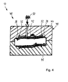
- a tubular second tube member 42 is injection molded around the first tube member 16 and the overstretched and shrunken tissue tube 30.
- the insert core 18 is for this purpose together with the first tube member 16 and the shrunk-on fabric tube 30 in a second injection mold 48, which again consists of two halves 44 and 46.
- the two halves 44 and 46 of the second injection mold 48 clamp the two above-mentioned, outer tube portions 38 of the first tube member 16 and shrunk in these tube sections 38 fabric tube 30. In this way, the first tube member 16 and the fabric tube 30 in the second Injection mold 48 with high dimensional accuracy held at its tube sections 38 in position.
- the second plastic used is 50 ACM with a filler content of 3%.
- the Shore hardness of this plastic is about 50 Shore A.
- the second plastic 50 is injected into the second injection mold 48, wherein in this second injection molding on the pressure hose 12 at the same time two end flanges 52 are formed as connecting elements.
- a cable clip 54 is formed as a connecting element in the middle of the wall of the pressure hose 12 with a metallic insert 56 arranged therein.
- one or more bellows can be formed in an embodiment of a pressure hose 12, not shown.
- different wall thicknesses can also be realized from different proportions of material in order, in particular, to increase the mobility of the material Optimize pressure hose with simultaneous pressure resistance.
- areas of different wall thicknesses and / or materials can also be formed particularly advantageously as a function of acoustical requirements to be met.
- the pressure hose 12 together with the insert core 18 is removed from the second injection mold 40. Subsequently, by means of an air-pressure pulse of the pressure hose 12 is removed from the insert core 18 and then the still over the second hose member 42 projecting outer hose sections 38 of the first hose member 16 with the sections of the fabric hose 30 still located thereon cut off.
Landscapes
- Engineering & Computer Science (AREA)
- Mechanical Engineering (AREA)
- Manufacturing & Machinery (AREA)
- General Engineering & Computer Science (AREA)
- Chemical & Material Sciences (AREA)
- Combustion & Propulsion (AREA)
- Injection Moulding Of Plastics Or The Like (AREA)
Priority Applications (3)
| Application Number | Priority Date | Filing Date | Title |
|---|---|---|---|
| PL12005407T PL2689917T3 (pl) | 2012-07-25 | 2012-07-25 | Sposób wytwarzania węża ciśnieniowego oraz wytworzony w ten sposób wąż ciśnieniowy |
| EP12005407.7A EP2689917B1 (fr) | 2012-07-25 | 2012-07-25 | Procédé de fabrication d'un tuyau flexible sous pression, et tuyau flexible ainsi produit |
| PCT/EP2013/065711 WO2014016377A1 (fr) | 2012-07-25 | 2013-07-25 | Procédé de fabrication d'un flexible de pression |
Applications Claiming Priority (1)
| Application Number | Priority Date | Filing Date | Title |
|---|---|---|---|
| EP12005407.7A EP2689917B1 (fr) | 2012-07-25 | 2012-07-25 | Procédé de fabrication d'un tuyau flexible sous pression, et tuyau flexible ainsi produit |
Publications (2)
| Publication Number | Publication Date |
|---|---|
| EP2689917A1 true EP2689917A1 (fr) | 2014-01-29 |
| EP2689917B1 EP2689917B1 (fr) | 2017-01-11 |
Family
ID=48856646
Family Applications (1)
| Application Number | Title | Priority Date | Filing Date |
|---|---|---|---|
| EP12005407.7A Not-in-force EP2689917B1 (fr) | 2012-07-25 | 2012-07-25 | Procédé de fabrication d'un tuyau flexible sous pression, et tuyau flexible ainsi produit |
Country Status (3)
| Country | Link |
|---|---|
| EP (1) | EP2689917B1 (fr) |
| PL (1) | PL2689917T3 (fr) |
| WO (1) | WO2014016377A1 (fr) |
Citations (7)
| Publication number | Priority date | Publication date | Assignee | Title |
|---|---|---|---|---|
| US1361206A (en) * | 1918-11-11 | 1920-12-07 | Williamson & Co R | Flexible gas-tubing |
| EP1065039A2 (fr) * | 1999-06-28 | 2001-01-03 | Tokai Rubber Industries, Ltd. | Méthode de fabrication d'un tuyau flexible de basse perméabilité à l'essence |
| US20040256016A1 (en) * | 2003-06-23 | 2004-12-23 | Tetsuya Arima | Vibration absorbing hose |
| DE102005033271A1 (de) * | 2004-07-15 | 2006-02-09 | Tokai Rubber Industries, Ltd., Komaki | Hochdruckbeständiger schwingungsdämpfender Schlauch und Verfahren zu seiner Herstellung |
| DE102005046367A1 (de) * | 2004-09-28 | 2006-04-06 | Tokai Rubber Industries, Ltd., Komaki | Hochdruckbeständiger, schwingungsdämpfender Schlauch und Verfahren zur Herstellung desselben |
| US7264021B1 (en) * | 2006-03-22 | 2007-09-04 | Tokai Rubber Industries, Ltd. | High-pressure resistant hose |
| DE102008058795A1 (de) | 2008-03-07 | 2009-09-10 | Deranco Grundstücksverwaltungs GmbH & Co. KG | Mittel zum Aufbringen |
Family Cites Families (1)
| Publication number | Priority date | Publication date | Assignee | Title |
|---|---|---|---|---|
| DE102008059795B4 (de) * | 2008-12-01 | 2014-08-21 | Etimex Technical Components Gmbh | Verfahren zum Herstellen eines Druckschlauchs durch Spritzgießen |
-
2012
- 2012-07-25 PL PL12005407T patent/PL2689917T3/pl unknown
- 2012-07-25 EP EP12005407.7A patent/EP2689917B1/fr not_active Not-in-force
-
2013
- 2013-07-25 WO PCT/EP2013/065711 patent/WO2014016377A1/fr not_active Ceased
Patent Citations (7)
| Publication number | Priority date | Publication date | Assignee | Title |
|---|---|---|---|---|
| US1361206A (en) * | 1918-11-11 | 1920-12-07 | Williamson & Co R | Flexible gas-tubing |
| EP1065039A2 (fr) * | 1999-06-28 | 2001-01-03 | Tokai Rubber Industries, Ltd. | Méthode de fabrication d'un tuyau flexible de basse perméabilité à l'essence |
| US20040256016A1 (en) * | 2003-06-23 | 2004-12-23 | Tetsuya Arima | Vibration absorbing hose |
| DE102005033271A1 (de) * | 2004-07-15 | 2006-02-09 | Tokai Rubber Industries, Ltd., Komaki | Hochdruckbeständiger schwingungsdämpfender Schlauch und Verfahren zu seiner Herstellung |
| DE102005046367A1 (de) * | 2004-09-28 | 2006-04-06 | Tokai Rubber Industries, Ltd., Komaki | Hochdruckbeständiger, schwingungsdämpfender Schlauch und Verfahren zur Herstellung desselben |
| US7264021B1 (en) * | 2006-03-22 | 2007-09-04 | Tokai Rubber Industries, Ltd. | High-pressure resistant hose |
| DE102008058795A1 (de) | 2008-03-07 | 2009-09-10 | Deranco Grundstücksverwaltungs GmbH & Co. KG | Mittel zum Aufbringen |
Also Published As
| Publication number | Publication date |
|---|---|
| EP2689917B1 (fr) | 2017-01-11 |
| WO2014016377A1 (fr) | 2014-01-30 |
| PL2689917T3 (pl) | 2017-07-31 |
Similar Documents
| Publication | Publication Date | Title |
|---|---|---|
| DE102019006280A1 (de) | Verfahren zur Herstellung einer formschlüssigen Lasteinleitung für stabförmige Fasernbundstrukturen sowie deren Gestaltung | |
| WO2012062497A1 (fr) | Dispositif de fixation pour une ligne et procédé de fixation d'une ligne | |
| DE102018222302A1 (de) | Verfahren zum Herstellen eines Drucktanks zur Speicherung von Brennstoff in einem Kraftfahrzeug und hiermit hergestellter Drucktank | |
| DE202007017460U1 (de) | Schlauchleitungsverbinder sowie Leitungssatz | |
| DE102008059795B4 (de) | Verfahren zum Herstellen eines Druckschlauchs durch Spritzgießen | |
| DE102011018217A1 (de) | Verfahren zur Herstellung von Federelementen aus Faserverbundwerkstoffen | |
| EP2689916B1 (fr) | Procédé de fabrication d'un tuyau flexible sous pression, et tuyau flexible ainsi produit | |
| EP2689917B1 (fr) | Procédé de fabrication d'un tuyau flexible sous pression, et tuyau flexible ainsi produit | |
| EP2689915B1 (fr) | Procédé de fabrication d'un tuyau flexible sous pression, et tuyau flexible ainsi produit | |
| DE10036235C2 (de) | Medienleitung aus gummiartigem Kunststoff, insbesondere Kühlwasserschlauch | |
| DE102014106860A1 (de) | Verfahren zur Herstellung eines Dämpferrohres aus einem Faserverbundwerkstoff für einen Schwingungsdämpfer | |
| DE102014209929B4 (de) | Schlauchverbindungs-Vorrichtung und Massage-Toy mit einer solchen Schlauchverbindungs-Vorrichtung | |
| WO2013050202A1 (fr) | Système de décharge de traction pour câbles, en particulier pour câbles optiques | |
| DE29820394U1 (de) | Tülle mit Verbindungsabschnitt | |
| EP1815578A1 (fr) | Capot de protection | |
| EP1264717A2 (fr) | Ensemble de construction de tuyaux pour conditionneurs d'air et procédé de fabrication de tuyaux | |
| DE102021002202A1 (de) | Flexibler schlauch, insbesondere staubsaugerschlauch | |
| DE102008045380A1 (de) | Kunststoffummanteltes Lager und Verfahren zu dessen Herstellung | |
| DE3603060C2 (fr) | ||
| DE102007020913A1 (de) | Verlegeprofil für ein Kabel | |
| DE4415730C1 (de) | Gekrümmter Schlauchabschnitt | |
| DE102020104035A1 (de) | Elektrischer Steckverbinder mit Biegeschutz | |
| DE19718096C2 (de) | Verfahren zum Anbringen eines einen Schlauch umgreifenden Formteils an einem Schlauchabschnitt | |
| DE102018200913A1 (de) | Bowdenzug mit Knickschutz | |
| DE2222180C2 (de) | Wärmeschrumpfbare Manschette |
Legal Events
| Date | Code | Title | Description |
|---|---|---|---|
| PUAI | Public reference made under article 153(3) epc to a published international application that has entered the european phase |
Free format text: ORIGINAL CODE: 0009012 |
|
| AK | Designated contracting states |
Kind code of ref document: A1 Designated state(s): AL AT BE BG CH CY CZ DE DK EE ES FI FR GB GR HR HU IE IS IT LI LT LU LV MC MK MT NL NO PL PT RO RS SE SI SK SM TR |
|
| AX | Request for extension of the european patent |
Extension state: BA ME |
|
| 17P | Request for examination filed |
Effective date: 20140728 |
|
| RBV | Designated contracting states (corrected) |
Designated state(s): AL AT BE BG CH CY CZ DE DK EE ES FI FR GB GR HR HU IE IS IT LI LT LU LV MC MK MT NL NO PL PT RO RS SE SI SK SM TR |
|
| 17Q | First examination report despatched |
Effective date: 20150302 |
|
| REG | Reference to a national code |
Ref country code: DE Ref legal event code: R079 Ref document number: 502012009252 Country of ref document: DE Free format text: PREVIOUS MAIN CLASS: B29C0067000000 Ipc: F16L0011080000 |
|
| GRAP | Despatch of communication of intention to grant a patent |
Free format text: ORIGINAL CODE: EPIDOSNIGR1 |
|
| RIC1 | Information provided on ipc code assigned before grant |
Ipc: F02M 35/10 20060101ALI20160906BHEP Ipc: B29C 45/16 20060101ALI20160906BHEP Ipc: B29D 23/00 20060101ALN20160906BHEP Ipc: B29C 61/02 20060101ALN20160906BHEP Ipc: F16L 11/08 20060101AFI20160906BHEP |
|
| INTG | Intention to grant announced |
Effective date: 20160921 |
|
| GRAS | Grant fee paid |
Free format text: ORIGINAL CODE: EPIDOSNIGR3 |
|
| GRAA | (expected) grant |
Free format text: ORIGINAL CODE: 0009210 |
|
| AK | Designated contracting states |
Kind code of ref document: B1 Designated state(s): AL AT BE BG CH CY CZ DE DK EE ES FI FR GB GR HR HU IE IS IT LI LT LU LV MC MK MT NL NO PL PT RO RS SE SI SK SM TR |
|
| REG | Reference to a national code |
Ref country code: GB Ref legal event code: FG4D Free format text: NOT ENGLISH |
|
| REG | Reference to a national code |
Ref country code: CH Ref legal event code: EP |
|
| REG | Reference to a national code |
Ref country code: AT Ref legal event code: REF Ref document number: 861624 Country of ref document: AT Kind code of ref document: T Effective date: 20170115 |
|
| REG | Reference to a national code |
Ref country code: IE Ref legal event code: FG4D Free format text: LANGUAGE OF EP DOCUMENT: GERMAN |
|
| REG | Reference to a national code |
Ref country code: DE Ref legal event code: R096 Ref document number: 502012009252 Country of ref document: DE |
|
| REG | Reference to a national code |
Ref country code: SE Ref legal event code: TRGR |
|
| REG | Reference to a national code |
Ref country code: LT Ref legal event code: MG4D |
|
| REG | Reference to a national code |
Ref country code: NL Ref legal event code: MP Effective date: 20170111 |
|
| PG25 | Lapsed in a contracting state [announced via postgrant information from national office to epo] |
Ref country code: NL Free format text: LAPSE BECAUSE OF FAILURE TO SUBMIT A TRANSLATION OF THE DESCRIPTION OR TO PAY THE FEE WITHIN THE PRESCRIBED TIME-LIMIT Effective date: 20170111 |
|
| REG | Reference to a national code |
Ref country code: FR Ref legal event code: PLFP Year of fee payment: 6 |
|
| PG25 | Lapsed in a contracting state [announced via postgrant information from national office to epo] |
Ref country code: IS Free format text: LAPSE BECAUSE OF FAILURE TO SUBMIT A TRANSLATION OF THE DESCRIPTION OR TO PAY THE FEE WITHIN THE PRESCRIBED TIME-LIMIT Effective date: 20170511 Ref country code: HR Free format text: LAPSE BECAUSE OF FAILURE TO SUBMIT A TRANSLATION OF THE DESCRIPTION OR TO PAY THE FEE WITHIN THE PRESCRIBED TIME-LIMIT Effective date: 20170111 Ref country code: LT Free format text: LAPSE BECAUSE OF FAILURE TO SUBMIT A TRANSLATION OF THE DESCRIPTION OR TO PAY THE FEE WITHIN THE PRESCRIBED TIME-LIMIT Effective date: 20170111 Ref country code: NO Free format text: LAPSE BECAUSE OF FAILURE TO SUBMIT A TRANSLATION OF THE DESCRIPTION OR TO PAY THE FEE WITHIN THE PRESCRIBED TIME-LIMIT Effective date: 20170411 Ref country code: FI Free format text: LAPSE BECAUSE OF FAILURE TO SUBMIT A TRANSLATION OF THE DESCRIPTION OR TO PAY THE FEE WITHIN THE PRESCRIBED TIME-LIMIT Effective date: 20170111 Ref country code: GR Free format text: LAPSE BECAUSE OF FAILURE TO SUBMIT A TRANSLATION OF THE DESCRIPTION OR TO PAY THE FEE WITHIN THE PRESCRIBED TIME-LIMIT Effective date: 20170412 |
|
| PG25 | Lapsed in a contracting state [announced via postgrant information from national office to epo] |
Ref country code: LV Free format text: LAPSE BECAUSE OF FAILURE TO SUBMIT A TRANSLATION OF THE DESCRIPTION OR TO PAY THE FEE WITHIN THE PRESCRIBED TIME-LIMIT Effective date: 20170111 Ref country code: RS Free format text: LAPSE BECAUSE OF FAILURE TO SUBMIT A TRANSLATION OF THE DESCRIPTION OR TO PAY THE FEE WITHIN THE PRESCRIBED TIME-LIMIT Effective date: 20170111 Ref country code: PT Free format text: LAPSE BECAUSE OF FAILURE TO SUBMIT A TRANSLATION OF THE DESCRIPTION OR TO PAY THE FEE WITHIN THE PRESCRIBED TIME-LIMIT Effective date: 20170511 Ref country code: BG Free format text: LAPSE BECAUSE OF FAILURE TO SUBMIT A TRANSLATION OF THE DESCRIPTION OR TO PAY THE FEE WITHIN THE PRESCRIBED TIME-LIMIT Effective date: 20170411 Ref country code: ES Free format text: LAPSE BECAUSE OF FAILURE TO SUBMIT A TRANSLATION OF THE DESCRIPTION OR TO PAY THE FEE WITHIN THE PRESCRIBED TIME-LIMIT Effective date: 20170111 |
|
| REG | Reference to a national code |
Ref country code: DE Ref legal event code: R097 Ref document number: 502012009252 Country of ref document: DE |
|
| PG25 | Lapsed in a contracting state [announced via postgrant information from national office to epo] |
Ref country code: EE Free format text: LAPSE BECAUSE OF FAILURE TO SUBMIT A TRANSLATION OF THE DESCRIPTION OR TO PAY THE FEE WITHIN THE PRESCRIBED TIME-LIMIT Effective date: 20170111 Ref country code: RO Free format text: LAPSE BECAUSE OF FAILURE TO SUBMIT A TRANSLATION OF THE DESCRIPTION OR TO PAY THE FEE WITHIN THE PRESCRIBED TIME-LIMIT Effective date: 20170111 Ref country code: SK Free format text: LAPSE BECAUSE OF FAILURE TO SUBMIT A TRANSLATION OF THE DESCRIPTION OR TO PAY THE FEE WITHIN THE PRESCRIBED TIME-LIMIT Effective date: 20170111 |
|
| PGFP | Annual fee paid to national office [announced via postgrant information from national office to epo] |
Ref country code: CZ Payment date: 20170720 Year of fee payment: 6 Ref country code: DE Payment date: 20170623 Year of fee payment: 6 Ref country code: GB Payment date: 20170724 Year of fee payment: 6 Ref country code: IT Payment date: 20170721 Year of fee payment: 6 Ref country code: FR Payment date: 20170720 Year of fee payment: 6 |
|
| PLBE | No opposition filed within time limit |
Free format text: ORIGINAL CODE: 0009261 |
|
| STAA | Information on the status of an ep patent application or granted ep patent |
Free format text: STATUS: NO OPPOSITION FILED WITHIN TIME LIMIT |
|
| PG25 | Lapsed in a contracting state [announced via postgrant information from national office to epo] |
Ref country code: DK Free format text: LAPSE BECAUSE OF FAILURE TO SUBMIT A TRANSLATION OF THE DESCRIPTION OR TO PAY THE FEE WITHIN THE PRESCRIBED TIME-LIMIT Effective date: 20170111 Ref country code: SM Free format text: LAPSE BECAUSE OF FAILURE TO SUBMIT A TRANSLATION OF THE DESCRIPTION OR TO PAY THE FEE WITHIN THE PRESCRIBED TIME-LIMIT Effective date: 20170111 |
|
| PGFP | Annual fee paid to national office [announced via postgrant information from national office to epo] |
Ref country code: SE Payment date: 20170724 Year of fee payment: 6 Ref country code: AT Payment date: 20170719 Year of fee payment: 6 Ref country code: PL Payment date: 20170718 Year of fee payment: 6 |
|
| 26N | No opposition filed |
Effective date: 20171012 |
|
| PG25 | Lapsed in a contracting state [announced via postgrant information from national office to epo] |
Ref country code: SI Free format text: LAPSE BECAUSE OF FAILURE TO SUBMIT A TRANSLATION OF THE DESCRIPTION OR TO PAY THE FEE WITHIN THE PRESCRIBED TIME-LIMIT Effective date: 20170111 |
|
| REG | Reference to a national code |
Ref country code: CH Ref legal event code: PL |
|
| REG | Reference to a national code |
Ref country code: IE Ref legal event code: MM4A |
|
| PG25 | Lapsed in a contracting state [announced via postgrant information from national office to epo] |
Ref country code: CH Free format text: LAPSE BECAUSE OF NON-PAYMENT OF DUE FEES Effective date: 20170731 Ref country code: LI Free format text: LAPSE BECAUSE OF NON-PAYMENT OF DUE FEES Effective date: 20170731 Ref country code: IE Free format text: LAPSE BECAUSE OF NON-PAYMENT OF DUE FEES Effective date: 20170725 |
|
| REG | Reference to a national code |
Ref country code: BE Ref legal event code: MM Effective date: 20170731 |
|
| PG25 | Lapsed in a contracting state [announced via postgrant information from national office to epo] |
Ref country code: LU Free format text: LAPSE BECAUSE OF NON-PAYMENT OF DUE FEES Effective date: 20170725 |
|
| PG25 | Lapsed in a contracting state [announced via postgrant information from national office to epo] |
Ref country code: BE Free format text: LAPSE BECAUSE OF NON-PAYMENT OF DUE FEES Effective date: 20170731 |
|
| PG25 | Lapsed in a contracting state [announced via postgrant information from national office to epo] |
Ref country code: MT Free format text: LAPSE BECAUSE OF FAILURE TO SUBMIT A TRANSLATION OF THE DESCRIPTION OR TO PAY THE FEE WITHIN THE PRESCRIBED TIME-LIMIT Effective date: 20170111 |
|
| REG | Reference to a national code |
Ref country code: DE Ref legal event code: R119 Ref document number: 502012009252 Country of ref document: DE |
|
| REG | Reference to a national code |
Ref country code: AT Ref legal event code: MM01 Ref document number: 861624 Country of ref document: AT Kind code of ref document: T Effective date: 20180725 |
|
| GBPC | Gb: european patent ceased through non-payment of renewal fee |
Effective date: 20180725 |
|
| PG25 | Lapsed in a contracting state [announced via postgrant information from national office to epo] |
Ref country code: CZ Free format text: LAPSE BECAUSE OF NON-PAYMENT OF DUE FEES Effective date: 20180725 Ref country code: GB Free format text: LAPSE BECAUSE OF NON-PAYMENT OF DUE FEES Effective date: 20180725 Ref country code: AT Free format text: LAPSE BECAUSE OF NON-PAYMENT OF DUE FEES Effective date: 20180725 Ref country code: FR Free format text: LAPSE BECAUSE OF NON-PAYMENT OF DUE FEES Effective date: 20180731 Ref country code: DE Free format text: LAPSE BECAUSE OF NON-PAYMENT OF DUE FEES Effective date: 20190201 |
|
| PG25 | Lapsed in a contracting state [announced via postgrant information from national office to epo] |
Ref country code: SE Free format text: LAPSE BECAUSE OF NON-PAYMENT OF DUE FEES Effective date: 20180726 |
|
| PG25 | Lapsed in a contracting state [announced via postgrant information from national office to epo] |
Ref country code: HU Free format text: LAPSE BECAUSE OF FAILURE TO SUBMIT A TRANSLATION OF THE DESCRIPTION OR TO PAY THE FEE WITHIN THE PRESCRIBED TIME-LIMIT; INVALID AB INITIO Effective date: 20120725 Ref country code: MC Free format text: LAPSE BECAUSE OF FAILURE TO SUBMIT A TRANSLATION OF THE DESCRIPTION OR TO PAY THE FEE WITHIN THE PRESCRIBED TIME-LIMIT Effective date: 20170111 |
|
| PG25 | Lapsed in a contracting state [announced via postgrant information from national office to epo] |
Ref country code: IT Free format text: LAPSE BECAUSE OF NON-PAYMENT OF DUE FEES Effective date: 20180725 |
|
| PG25 | Lapsed in a contracting state [announced via postgrant information from national office to epo] |
Ref country code: CY Free format text: LAPSE BECAUSE OF NON-PAYMENT OF DUE FEES Effective date: 20170111 |
|
| PG25 | Lapsed in a contracting state [announced via postgrant information from national office to epo] |
Ref country code: MK Free format text: LAPSE BECAUSE OF FAILURE TO SUBMIT A TRANSLATION OF THE DESCRIPTION OR TO PAY THE FEE WITHIN THE PRESCRIBED TIME-LIMIT Effective date: 20170111 |
|
| PG25 | Lapsed in a contracting state [announced via postgrant information from national office to epo] |
Ref country code: PL Free format text: LAPSE BECAUSE OF NON-PAYMENT OF DUE FEES Effective date: 20180725 |
|
| PG25 | Lapsed in a contracting state [announced via postgrant information from national office to epo] |
Ref country code: TR Free format text: LAPSE BECAUSE OF FAILURE TO SUBMIT A TRANSLATION OF THE DESCRIPTION OR TO PAY THE FEE WITHIN THE PRESCRIBED TIME-LIMIT Effective date: 20170111 |
|
| PG25 | Lapsed in a contracting state [announced via postgrant information from national office to epo] |
Ref country code: AL Free format text: LAPSE BECAUSE OF FAILURE TO SUBMIT A TRANSLATION OF THE DESCRIPTION OR TO PAY THE FEE WITHIN THE PRESCRIBED TIME-LIMIT Effective date: 20170111 |