EP2689939B1 - Stahlseil zur verstärkung eines gummiartikels und luftreifen damit - Google Patents
Stahlseil zur verstärkung eines gummiartikels und luftreifen damit Download PDFInfo
- Publication number
- EP2689939B1 EP2689939B1 EP12760598.8A EP12760598A EP2689939B1 EP 2689939 B1 EP2689939 B1 EP 2689939B1 EP 12760598 A EP12760598 A EP 12760598A EP 2689939 B1 EP2689939 B1 EP 2689939B1
- Authority
- EP
- European Patent Office
- Prior art keywords
- belt
- tire
- steel cord
- filament
- belt layer
- Prior art date
- Legal status (The legal status is an assumption and is not a legal conclusion. Google has not performed a legal analysis and makes no representation as to the accuracy of the status listed.)
- Active
Links
Images
Classifications
-
- D—TEXTILES; PAPER
- D02—YARNS; MECHANICAL FINISHING OF YARNS OR ROPES; WARPING OR BEAMING
- D02G—CRIMPING OR CURLING FIBRES, FILAMENTS, THREADS, OR YARNS; YARNS OR THREADS
- D02G3/00—Yarns or threads, e.g. fancy yarns; Processes or apparatus for the production thereof, not otherwise provided for
- D02G3/44—Yarns or threads characterised by the purpose for which they are designed
- D02G3/48—Tyre cords
-
- B—PERFORMING OPERATIONS; TRANSPORTING
- B60—VEHICLES IN GENERAL
- B60C—VEHICLE TYRES; TYRE INFLATION; TYRE CHANGING; CONNECTING VALVES TO INFLATABLE ELASTIC BODIES IN GENERAL; DEVICES OR ARRANGEMENTS RELATED TO TYRES
- B60C9/00—Reinforcements or ply arrangement of pneumatic tyres
- B60C9/0007—Reinforcements made of metallic elements, e.g. cords, yarns, filaments or fibres made from metal
-
- B—PERFORMING OPERATIONS; TRANSPORTING
- B60—VEHICLES IN GENERAL
- B60C—VEHICLE TYRES; TYRE INFLATION; TYRE CHANGING; CONNECTING VALVES TO INFLATABLE ELASTIC BODIES IN GENERAL; DEVICES OR ARRANGEMENTS RELATED TO TYRES
- B60C9/00—Reinforcements or ply arrangement of pneumatic tyres
- B60C9/0057—Reinforcements comprising preshaped elements, e.g. undulated or zig-zag filaments
-
- B—PERFORMING OPERATIONS; TRANSPORTING
- B60—VEHICLES IN GENERAL
- B60C—VEHICLE TYRES; TYRE INFLATION; TYRE CHANGING; CONNECTING VALVES TO INFLATABLE ELASTIC BODIES IN GENERAL; DEVICES OR ARRANGEMENTS RELATED TO TYRES
- B60C9/00—Reinforcements or ply arrangement of pneumatic tyres
- B60C9/18—Structure or arrangement of belts or breakers, crown-reinforcing or cushioning layers
-
- B—PERFORMING OPERATIONS; TRANSPORTING
- B60—VEHICLES IN GENERAL
- B60C—VEHICLE TYRES; TYRE INFLATION; TYRE CHANGING; CONNECTING VALVES TO INFLATABLE ELASTIC BODIES IN GENERAL; DEVICES OR ARRANGEMENTS RELATED TO TYRES
- B60C9/00—Reinforcements or ply arrangement of pneumatic tyres
- B60C9/18—Structure or arrangement of belts or breakers, crown-reinforcing or cushioning layers
- B60C9/1835—Rubber strips or cushions at the belt edges
- B60C9/185—Rubber strips or cushions at the belt edges between adjacent or radially below the belt plies
-
- D—TEXTILES; PAPER
- D07—ROPES; CABLES OTHER THAN ELECTRIC
- D07B—ROPES OR CABLES IN GENERAL
- D07B1/00—Constructional features of ropes or cables
- D07B1/06—Ropes or cables built-up from metal wires, e.g. of section wires around a hemp core
- D07B1/0606—Reinforcing cords for rubber or plastic articles
- D07B1/062—Reinforcing cords for rubber or plastic articles the reinforcing cords being characterised by the strand configuration
-
- D—TEXTILES; PAPER
- D07—ROPES; CABLES OTHER THAN ELECTRIC
- D07B—ROPES OR CABLES IN GENERAL
- D07B1/00—Constructional features of ropes or cables
- D07B1/06—Ropes or cables built-up from metal wires, e.g. of section wires around a hemp core
- D07B1/0606—Reinforcing cords for rubber or plastic articles
- D07B1/0646—Reinforcing cords for rubber or plastic articles comprising longitudinally preformed wires
-
- D—TEXTILES; PAPER
- D07—ROPES; CABLES OTHER THAN ELECTRIC
- D07B—ROPES OR CABLES IN GENERAL
- D07B1/00—Constructional features of ropes or cables
- D07B1/06—Ropes or cables built-up from metal wires, e.g. of section wires around a hemp core
- D07B1/0606—Reinforcing cords for rubber or plastic articles
- D07B1/0646—Reinforcing cords for rubber or plastic articles comprising longitudinally preformed wires
- D07B1/0653—Reinforcing cords for rubber or plastic articles comprising longitudinally preformed wires in the core
-
- B—PERFORMING OPERATIONS; TRANSPORTING
- B60—VEHICLES IN GENERAL
- B60C—VEHICLE TYRES; TYRE INFLATION; TYRE CHANGING; CONNECTING VALVES TO INFLATABLE ELASTIC BODIES IN GENERAL; DEVICES OR ARRANGEMENTS RELATED TO TYRES
- B60C9/00—Reinforcements or ply arrangement of pneumatic tyres
- B60C9/18—Structure or arrangement of belts or breakers, crown-reinforcing or cushioning layers
- B60C9/1835—Rubber strips or cushions at the belt edges
- B60C2009/1842—Width or thickness of the strips or cushions
-
- B—PERFORMING OPERATIONS; TRANSPORTING
- B60—VEHICLES IN GENERAL
- B60C—VEHICLE TYRES; TYRE INFLATION; TYRE CHANGING; CONNECTING VALVES TO INFLATABLE ELASTIC BODIES IN GENERAL; DEVICES OR ARRANGEMENTS RELATED TO TYRES
- B60C9/00—Reinforcements or ply arrangement of pneumatic tyres
- B60C9/18—Structure or arrangement of belts or breakers, crown-reinforcing or cushioning layers
- B60C9/20—Structure or arrangement of belts or breakers, crown-reinforcing or cushioning layers built-up from rubberised plies each having all cords arranged substantially parallel
- B60C2009/2061—Physical properties or dimensions of the belt coating rubber
- B60C2009/2067—Thickness
-
- B—PERFORMING OPERATIONS; TRANSPORTING
- B60—VEHICLES IN GENERAL
- B60C—VEHICLE TYRES; TYRE INFLATION; TYRE CHANGING; CONNECTING VALVES TO INFLATABLE ELASTIC BODIES IN GENERAL; DEVICES OR ARRANGEMENTS RELATED TO TYRES
- B60C9/00—Reinforcements or ply arrangement of pneumatic tyres
- B60C9/18—Structure or arrangement of belts or breakers, crown-reinforcing or cushioning layers
- B60C9/20—Structure or arrangement of belts or breakers, crown-reinforcing or cushioning layers built-up from rubberised plies each having all cords arranged substantially parallel
- B60C2009/2074—Physical properties or dimension of the belt cord
- B60C2009/2077—Diameters of the cords; Linear density thereof
-
- D—TEXTILES; PAPER
- D07—ROPES; CABLES OTHER THAN ELECTRIC
- D07B—ROPES OR CABLES IN GENERAL
- D07B2201/00—Ropes or cables
- D07B2201/20—Rope or cable components
- D07B2201/2001—Wires or filaments
- D07B2201/2006—Wires or filaments characterised by a value or range of the dimension given
-
- D—TEXTILES; PAPER
- D07—ROPES; CABLES OTHER THAN ELECTRIC
- D07B—ROPES OR CABLES IN GENERAL
- D07B2201/00—Ropes or cables
- D07B2201/20—Rope or cable components
- D07B2201/2015—Strands
- D07B2201/2024—Strands twisted
- D07B2201/2029—Open winding
-
- D—TEXTILES; PAPER
- D07—ROPES; CABLES OTHER THAN ELECTRIC
- D07B—ROPES OR CABLES IN GENERAL
- D07B2201/00—Ropes or cables
- D07B2201/20—Rope or cable components
- D07B2201/2047—Cores
- D07B2201/2051—Cores characterised by a value or range of the dimension given
-
- D—TEXTILES; PAPER
- D07—ROPES; CABLES OTHER THAN ELECTRIC
- D07B—ROPES OR CABLES IN GENERAL
- D07B2201/00—Ropes or cables
- D07B2201/20—Rope or cable components
- D07B2201/2047—Cores
- D07B2201/2052—Cores characterised by their structure
- D07B2201/2065—Cores characterised by their structure comprising a coating
Definitions
- the present invention relates to a steel cord for reinforcing rubber articles and a pneumatic radial tire (hereinafter, also simply referred to as "steel cord” and “tire”, respectively) using the same, more specifically, to a steel cord for reinforcing rubber articles which, when applied to a belt of a tire, can attain lightweight without reducing the durability of the tire, and in particular, to a steel cord for reinforcing rubber articles in which the properties of a treat after rubberizing are excellent and a pneumatic radial tire using the same.
- a reinforcing member for a carcass constituting a skeleton of a radial tire for a passenger vehicle in particular, a belt which is generally used as a reinforcing member for a crown portion of a carcass is mainly constituted such that two or more steel belt layers composed of layers in which rubberized steel cord obliquely arranged with respect to the tire equatorial plane are used, and that the steel cords in the belt layers are crossed each other.
- a method in which the weight of a tire is reduced include a method in which the amount of rubber used in a belt treat is reduced and the thickness of the belt is reduced.
- BES belt edge separation
- Patent Document 2 discloses a steel cord having a 2+3 structure for the purpose of improving the durability of a belt.
- Patent Documents 3 to 7 disclose a steel cord having a 2+3 structure for the purpose of improving a variety of physical properties or workability of a reinforcing member of a tire which are needed.
- Patent Document 1 Even a steel cord of Patent Document 1 is far from fulfilling the demand of lightweight of a tire which is needed today, and a technique of further lightweight is needed.
- a steel cord of Patent Document 2 has an improved durability by increasing permeability of rubber into steel cords, lightweight of a tire is not examined. Further, it is the status quo that, also for steel cords of Patent Documents 3 to 7, examination regarding lightweight of a tire is not necessarily satisfactory.
- a steel cord having a M+N structure is conventionally manufactured by a buncher type strander from the viewpoint of productivity.
- a torsion is applied to a steel filament constituting the steel cord, whereby a steel cord having a M+N structure is constituted by steel filaments each having considerably varied torsion.
- a treat a rubber-steel cord complex formed by rubberizing a steel cord having an M+N structure (hereinafter, referred to as a treat)
- this treat is cut in a cutting process, the end of the treat is sprung out and curled, and the workability deteriorates, which has been problematic.
- Such problems have not been examined sufficiently in Patent Documents 1 to 7, which is the status quo.
- an object of the present invention is to provide a steel cord for reinforcing rubber articles which, when applied to a belt of a tire, can attain lightweight without reducing the durability of the tire, and a pneumatic radial tire using the same.
- Another object of the present invention is to provide a steel cord for reinforcing rubber articles in which the properties of a treat after rubberizing are excellent and a pneumatic radial tire using the same.
- the present inventor intensively studied to find that, in a steel cord having a 2+N structure, if the diameters of a core filament and a sheath filament satisfy a predetermined relationship, the weight of a belt treat can be reduced while maintaining the distance between cords of the belt, and that if the average corrugation rates of a core filament and a sheath filament satisfy a predetermined relationship, the properties of a treat can be improved, thereby completing the present invention.
- a steel cord for reinforcing rubber articles of the present invention is a steel cord for reinforcing rubber articles as claimed in claim 1.
- d1 / d2 is 1.1 to less than 1.7. In the present invention, d1 / d2 is preferably 1.1 to less than 1.4. Further, in the present invention, letting the average corrugation rate of the core filament be H1, and the average corrugation rate of the sheath filament be H2, preferably H1 > H2. Still further, in the present invention, the H1 is preferably 70 to 110%. In the present invention, preferably the d1 is 0.16 to 0.32 mm, and the d2 is 0.12 to 0.29 mm. Further, in the present invention, the number of the sheath filament is preferably three.
- a pneumatic radial tire of the present invention is a pneumatic radial tire comprising a carcass composed of at least one carcass layer toroidally bridging between a left-right pair of bead cores, a tread portion that is arranged outside of a crown region of the carcass in the tire radial direction to form a ground contacting portion, and a belt composed of at least two belt layers which are arranged between the tread portion and a crown region of the carcass to form a reinforcing portion, wherein both a first belt layer and a second belt layer which are the first layer and the second layer of the belt are formed such that steel cords for reinforcing rubber articles of the above-mentioned the present invention are arranged in parallel in the belt width direction and embedded in coating rubber.
- d1/ d2 is 1.1 to less than 1.7. In the present invention, the d1/d2 is preferably 1.1 to less than 1.4. Further, in the present invention, letting the average corrugation rate of the core filament be H1, and the average corrugation rate of the sheath filament be H2, preferably H1 > H2. Still further, in the present invention, the H1 is preferably 70 to 110%. Preferably d1 is 0.16 to 0.32 mm, and d2 is 0.12 to 0.29 mm. Further, in the present invention, the number of the sheath filaments is preferably three.
- the gauge of a rubber layer between steel cords of a first belt layer and a second belt layer at the end portion of the second belt layer is preferably larger than that at the tire center portion.
- the thickness of the belt layer is preferably 0.85 to 1.65 mm.
- a steel cord for reinforcing rubber articles which, when applied to a belt of a tire, can attain lightweight without reducing the durability of the tire, in particular, a steel cord for reinforcing rubber articles in which the properties after a treat is rubberized are excellent and a pneumatic radial tire using the same can be provided.
- a steel cord of the present invention is a steel cord for reinforcing rubber articles comprising a core formed by arranging two core filaments in parallel without being twisted together, and N, suitably, two to four, particularly suitably, three sheath filaments which are twisted together around the core.
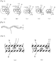
- the minor axis of a steel cord 10 having a 2+N (2 ⁇ N ⁇ 4) structure (in the illustrated drawings, a 2+3 structure) is ruled by the diameter of a sheath filament 2. Accordingly, as mentioned below, by making the diameter of the sheath filament 2 d2 smaller than the diameter of the core filament 1 d1, the minor axis of a steel cord can be made small.
- the thickness of the belt layer can be made thin while maintaining the distance between a steel cord of the first belt layer and a steel cord of the second belt layer.
- d1/d2 is preferably 1.1 to less than 1.7.
- the gauge of the inside of a first belt layer in the tire radial direction and the gauge of the outside of a second belt layer in the tire radial direction can be made thick while maintaining the distance between the steel cord of the first belt layer and the steel cord of the second belt layer the same.
- d1/d2 when d1/d2 is 1.7 or higher, the bending of the steel cord 10 becomes flexible, the fatigability against the core filament 1 is decreased.
- d1/d2 when d1/d2 is less than 1.1, gauges G1 and G2 of the inside of the first belt layer in the tire radial direction and the outside of the second belt layer in the tire radial direction can not be secured.
- d1/d2 is 1.1 to less than 1.4.
- the steel cord of the present invention preferably satisfies, letting the average corrugation rate of core filament 1 be H1, and the average corrugation rate of sheath filament 2 be H2, the relationship of H1 > H2.
- the average of the amplitude A Aave. means the average of the maximum and minimum, A1 and A2 of the amplitude of a filament measured after unravelling the steel cord.
- Fig. 2 is an explanatory drawing illustrating the amplitude of a filament.
- a treat which is a material of a belt layer constituting a tire is generally manufactured by aligning a large number of steel cords in parallel and arranging an unvulcanized rubber on top and bottom of the steel cords to rubberize the steel cords.
- N 2 to 4
- the torsions of a core filament 1 and a sheath filament 2 are generated in opposite directions, respectively.
- Fig. 3 is a partial cross-sectional view of a treat; (a) is the case where H1 ⁇ H2, (b) is the case where H1 > H2.
- H1 the average corrugation rate H1(%) of the core filament 1
- the position of the core filament 1 is hardly changed, and therefore, the core filament 1 does not come in touch with a coating rubber 3a, 3b which are arranged on the top and bottom of the steel cord and only a sheath filament 2 is in contact with the coating rubber 3a, 3b.
- the steel cord of the present invention by setting H1 > H2, and providing a portion where, in the longer direction of the steel cord, the core filament 1 and the coating rubber 3a, 3b are in contact with each other, rotation of the core filament 1 due to torsion is prevented to avoid curl of the treat when a treat is cut.
- the value of H1/H2 is 1.10 to 1.40.
- the average corrugation rate H1(%) of the core filament 1 is preferably 70 to 110%.
- H1 is less than 70%, a treat may be curled influenced by the average corrugation rate H2 of the sheath filament 2, which is not preferred.
- H1 is larger than 110%, the cord properties of the steel cord 10 may be unstable, which is not preferred.
- the diameter of the core filament 1 d1 is preferably 0.16 to 0.32 mm, and the diameter of the sheath filament 2 d2 is preferably 0.12 to 0.29 mm. If the filament diameter is higher than the above-mentioned range, even when the steel cord of the present invention is used as a belt reinforcing member, a sufficient effect of lightweight may not be obtained. On the other hand, when the filament diameter is less than the above-mentioned range, the belt strength may be insufficient.
- a steel filament having a tensile strength of 2700 N/mm 2 or higher is preferably used.
- a steel filament having a high tensile strength those having carbon by at least 0.72 % by mass, particularly at least 0.82 % by mass can be suitably employed.
- conditions such as the twist direction of the sheath filament 2, and the twist pitch are not particularly restricted, and the belt reinforcing member is appropriately constituted according to a conventional method.
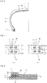
- Fig. 4 illustrates a half sectional view of one suitable example of a pneumatic radial tire of the present invention.
- the illustrated tire comprises a tread portion 11 which is arranged at a crown region of a carcass and forms a ground contacting portion, a pair of sidewall portions 12 which are continued to the both side portions of the tread portion 11 and extend inside in the tire radial direction, and a bead portion 13 which is continued to the inner circumference of each sidewall portion 12.
- the tread portion 11, sidewall portion 12 and bead portion 13 are reinforced by a carcass 14 composed of one carcass layer extending toroidally from one bead portion 13 to the other bead portion 13.
- the tread portion 11 is reinforced by a belt composed of at least two layers, in the illustrated example, two layers of a first belt layer 15a and a second belt layer 15b arranged outside a crown region of the carcass 14 in the tire radial direction, which are described below in detail.
- the number of carcass layers of the carcass 14 may be plural, and an organic fiber cord which extends in a direction substantially orthogonal to the tire circumferential direction, for example, in an angle of 70 to 90° can be suitably used.
- both the first belt layer 15a and the second belt layer 15b are formed such that steel cords for reinforcing rubber articles comprising a core formed by arranging two core filaments in parallel without being twisted together, and N (2 ⁇ N ⁇ 4) sheath filaments which are twisted together around the core, wherein, letting the diameter of the core filament be d1, and the diameter of the sheath filament be d2, d1 > d2 are embedded in a coating rubber in parallel with the tire width direction such that the major axis is in the tire width direction.
- the thickness of the belt layer can be thin while maintaining the distance between a steel cord of the first belt layer 15a and a steel cord of the second belt layer 15b.
- lightweight of a belt can be attained without reducing the resistance against BES, a so-called BES resistance.
- the amount of steel used can be reduced, lightweight of a tire further can be attained.
- Fig. 5 is an enlarged partial cross-sectional view of a belt of a pneumatic radial tire; (a) represents a conventional tire and (b) represents a tire according to the present invention.
- d1 > d2 increase in the cord diameter in the longitudinal direction compared with a conventional steel cord can be suppressed.
- the gauge G1 of the inside of a first belt layer 15a in the tire radial direction and the gauge G2 of the outside of a second belt layer 15b in the tire radial direction can be made thick while maintaining the distance D between the steel cord of the first belt layer 15a and the steel cord of the second belt layer 15b the same and maintaining the BES resistance.
- the adhesion durability of the belt can be improved.
- d1/d2 is preferably 1.1 to less than 1.7.
- the adhesion durability can be improved, and at the same time, the belt breaking strength can be secured.
- the bending of the steel cord 10 becomes flexible, the fatigability against the core filament 1 is decreased in some cases.
- gauges G1 and G2 of the inside of the first belt layer in the tire radial direction and the outside of the second belt layer in the tire radial direction can not be secured in some cases.
- d1/d2 is 1.1 to less than 1.4.
- the average corrugation rate of the core filament 1 be H1 and the average corrugation rate of the sheath filament 2 be H2, the relationship H1 > H2 is preferably satisfied. This is because since a treat for which a steel cord of the present invention is used does not curl, and the properties of the cord for itself is stable, the treat has an excellent workability during the manufacture of a tire.
- a cross belt formed by laminating a first belt layer 15a and a second belt layer 15b such that the cords which constitute the layers are crossed with each other sandwiching an equatorial plane is preferred.
- a belt layer may further be arranged, or a circumferential direction belt layer composed of a layer formed by rubberizing cords aligned substantially in parallel to the tire circumferential direction may be provided.
- a cord composed of an organic fiber can be suitably used.
- a cord composed of a polyester fiber, a nylon fiber, an aramid fiber, or a polyketone fiber can be suitably used.
- the diameter of the core filament 1 d1 is 0.16 to 0.32 mm, and the diameter of the sheath filament 2 d2 is 0.12 to 0.29 mm.
- the filament diameter is larger than the above-mentioned range, a sufficient lightweight effect may not be obtained.
- the filament diameter is smaller than the above-mentioned range, the belt strength may be insufficient.
- Fig. 6 illustrates an enlarged partial cross-sectional view illustrating the vicinity of the end portion of a belt layer according to a suitable embodiment of a pneumatic radial tire of the present invention.
- a gauge H E of a rubber layer between steel cords 16 of the first belt layer 15a and the second belt layer 15b at the end of the second belt layer 15b is preferably larger than a gauge H C at the tire center portion.
- H E is 1.3 to 3.0 times H C , and preferably 1.8 to 2.6 times H C .
- the thicknesses of belt layer t1, t2 are 0.85 to 1.65 mm, more suitably, 0.95 to 1.35 mm (see Fig. 6 ).
- the thicknesses of the belt layers t1, t2 are less than 0.85 mm, a sufficient durability can not be obtained in some cases; on the other hand, when the thicknesses of the belt layers t1, t2 are not less than 1.65 mm, a sufficient lightweight effect can not be obtained in some cases.
- the end count of steel cords in a belt is preferably 22 to 57 /50 mm.
- the end count is less than the above-mentioned range, the tensile strength may be insufficient or the rigidity of the belt may be decreased, which are not preferred.
- the end count is larger than the above-mentioned range, it becomes difficult to secure a cord interval, which makes it difficult to effectively restrict the BES, and the belt durability may be reduced.
- a steel filament having a tensile strength of 2700 N/mm 2 or higher is preferably used in order to secure the belt strength.
- a steel filament having a high tensile strength those having carbon by at least 0,72 % by mass, particularly at least 0.82 % by mass can be suitably employed.
- conditions such as the twist direction of the sheath filament 2, and the twist pitch are not particularly restricted, and the belt reinforcing member is appropriately constituted according to a conventional method.
- a pneumatic radial tire of the present invention can be suitably used as an automobile tire.
- a gas with which the tire to be filled a normal air or an air whose oxygen partial pressure is adjusted, as well as an inert gas such as nitrogen, argon or helium can be used.
- Tires having a tire size of 195/65R15 were manufactured by using, as a belt reinforcing member, a steel cord having a structure indicated in the Tables 1 to 4 below.
- the belt was composed of three belt layers; a steel cord indicated in the Tables 1 to 4 below was applied to a first belt layer and a second belt layer.
- the implantation angle of the steel cord was set to ⁇ 26° with respect to the tire circumferential direction.
- As the outermost belt layer a circumferential direction belt layer composed of a layer formed by rubberizing organic fiber cords aligned substantially in parallel to the tire circumferential direction was arranged. For each obtained tire, the durability (BES performance) and the tire weight thereof were evaluated according to the below-mentioned procedure.
- Tires having a tire size of 265/70R16 were manufactured by using, as a belt reinforcing member, a steel cord having a structure indicated in the Table 5 below.
- the belt was composed of three belt layers; a steel cord indicated in the Table 5 below was applied to a first belt layer and a second belt layer.
- the implantation angle of the steel cord was set to ⁇ 24° with respect to the tire circumferential direction.
- As the outermost belt layer a circumferential direction belt layer composed of a layer formed by rubberizing organic fiber cords aligned substantially in parallel to the tire circumferential direction was arranged.
- the durability (BES performance) and the tire weight thereof were evaluated according to the below-mentioned procedure.
- test tire was mounted on a standard rim which is defined in JATMA standards, and then, the tire was inflated to an inner pressure of 210 kPa and mounted on a passenger vehicle. A load of twice the normal load was applied and the vehicle was allowed to travel on a pavement surface for 20000 km. Then, the tire was dissected to compare the separation length at the belt end portion.
- Example 1-1 to 1-4 and Comparative Example 1-2 with reference to Comparative Example 1-1 in Example 1-5 and Comparative Example 1-4 with reference to Comparative Example 1-3, in Example 1-6 and 1-7 with reference to Comparative Example 1-5, in Examples 1-8 to 1-10 with reference to Comparative Example 1-6, in Example 1-11, 1-12 and Comparative Example 1-8 with reference to Comparative Example 1-7, when the tire weight is reduced by not less than 200 g, the tire was evaluated as "O", and when the tire weight is reduced by 100 g to less than 200 g, the tire was evaluated as " ⁇ ". The results are listed on the Tables 1 to 5.
- Tires having a tire size of 195/65R15 were manufactured by using, as a belt reinforcing member, a steel cord having a structure indicated in the Tables 6 to 8 below.
- the belt was composed of three belt layers; a steel cord indicated in the Tables 6 to 8 below was applied to a first belt layer and a second belt layer.
- the implantation angle of the steel cord was set to ⁇ 26° with respect to the tire circumferential direction.
- As the outermost belt layer a circumferential direction belt layer composed of a layer formed by rubberizing organic fiber cords aligned substantially in parallel to the tire circumferential direction was arranged. For each obtained tire, the durability (BES performance) and the tire weight thereof were evaluated according to the below-mentioned procedure.
- test tire was mounted on a standard rim which is defined in JATMA standards, and then, the tire was inflated to an inner pressure of 210 kPa and mounted on a passenger vehicle. A load of twice the normal load was applied and the vehicle was allowed to travel on a pavement surface for 20000 km. Then, the tire was dissected to compare the separation length at the belt end portion.
- the results are listed on the Tables 6 to 8 in combination.
- a treat was manufactured by paralleling a plurality of steel cords having a structure indicated in the Tables 6 to 8 below to have the end count indicated in the same Tables and covering the steel cords from the top with an unvulcanized rubber from the top and bottom. Each obtained treat was cut and whether a lift occurred in the treat or not was observed.
- Example 2-1 to 2-3 and Comparative Example 2-2 with reference to Comparative Example 2-1 in Example 2-4 with reference to Comparative Example 2-3, and in Examples 2-5 to 2-6 with reference to Comparative Example 2-4, when the treat curl properties were improved, the evaluation was represented by " ⁇ ", when the treat curl properties were similar or poor, the evaluation was represented by " ⁇ ".
- the obtained results are listed on the Tables 6 to 8.
- a steel cord having a structure indicated in the Tables 6 to 8 was fusion cut into a test piece having a length of 1m. By using a projector, the test piece was magnified 20 times to observe a lift of sheath filament from a core filament.
- Example 2-1 to 2-3 and Comparative Examples 2-2 to 2-3 with reference to Comparative Example 2-1 in Example 2-4 with reference to Comparative Example 2-4, and in Examples 2-5 to 2-6 with reference to Comparative Example 2-6, when the cord properties stability was improved, the evaluation was represented by " ⁇ ", when the treat curl properties were similar or poor, the evaluation was represented by " ⁇ ".
- the obtained results are listed on the Tables 6 to 8.
- a treat was manufactured by paralleling a plurality of steel cords having a structure indicated in the Table 9 below to have the end count indicated in the same Tables and covering the steel cords from the top with an unvulcanized rubber from the top and bottom.
- the thickness of the treat was set to 1.20 mm.
- the treat curl properties and cord properties stability thereof were evaluated according to the below-mentioned procedure.
- a steel cord having a structure indicated in the Table 9 was fusion cut into a test piece having a length of 1m. By using a projector, the test piece was magnified 20 times to observe a lift of sheath filament from a core filament. With reference to Comparative Example 3-1, when the cord properties stability was improved, the evaluation was represented by " ⁇ ", when the treat curl properties were similar or poor, the evaluation was represented by " ⁇ ", The obtained results are listed on the Table 9.
- a steel cord for reinforcing rubber articles of the present invention was those which, when applied to a belt of a tire, can attain lightweight without reducing the durability of the tire. From the Table 9, it was confirmed that a steel cord for reinforcing rubber articles of the present invention had excellent properties of a treat after rubberizing.
Landscapes
- Engineering & Computer Science (AREA)
- Mechanical Engineering (AREA)
- Textile Engineering (AREA)
- Ropes Or Cables (AREA)
- Tires In General (AREA)
Claims (15)
- Stahlseil (10) zum Verstärken von Gummiartikeln, wobei das Stahlseil (10) einen Kern umfasst, welcher gebildet wird, durch
Anordnen von zwei Kernfilamenten (1) parallel zueinander, ohne dass diese miteinander verdrillt werden, und von N (2 ≤ N ≤ 4) Mantelfilamenten (2), welche um den Kern miteinander verdrillt werden,
dadurch gekennzeichnet, dass, wenn der Durchmesser des Kernfilaments d1 ist und der Durchmesser des Mantelfilaments d2 ist, d1/d2 zwischen 1,1 und weniger als 1,7 liegt. - Stahlseil zum Verstärken von Gummiartikeln nach Anspruch 1, wobei das Verhältnis d1/d2 zwischen 1,1 und weniger als 1,4 ist.
- Stahlseil zum Verstärken von Gummiartikeln nach Anspruch 1, wobei, wenn die mittlere Wellungsrate des Kernfilaments H1 ist und die mittlere Wellungsrate des Mantelfilaments H2 ist, H1 > H2, wobei die mittlere Wellungsrate H(%) des Kernfilaments 1 und des Mantelfilaments 2 durch die folgende Formel definiert ist, wobei der Mittelwert der Amplitude A des Filaments Aave. ist: mittlere Wellungsrate H(%) = 100 x Aave./(2 x d1 + d2), und wobei der Mittelwert der Amplitude A Aave. der Mittelwert des Maximums und des Minimums A1 und A2 der Amplitude eines Filaments ist, welche nach dem Entwirren des Stahlseils gemessen wird.
- Stahlseil zum Verstärken von Gummiartikeln nach Anspruch 1, wobei H1 zwischen 70 und 110% liegt.
- Stahlseil zum Verstärken von Gummiartikeln nach Anspruch 1, wobei d1 zwischen 0,16 und 0,32 mm liegt und d2 zwischen 0,12 und 0,29 mm liegt.
- Stahlseil zum Verstärken von Gummiartikeln nach Anspruch 1, wobei die Anzahl der Mantelfilamente drei ist.
- Radialer Luftreifen, umfassend eine Karkasse (14), welche aus mindestens einer Karkassenschicht besteht, welche ein Links-Rechts-Paar von Wulstkernen torusförmig überbrückt, einen Laufflächenabschnitt (11), welcher außerhalb eines Kronenbereichs der Karkasse in der Reifenradialrichtung angeordnet ist, um einen Bodenkontaktabschnitt zu bilden, und einen Gürtel, welcher aus mindestens zwei Gürtelschichten (15a, 15b) besteht, welche zwischen dem Laufflächenabschnitt und einem Kronenbereich der Karkasse angeordnet sind, um einen Verstärkungsabschnitt zu bilden,
wobei sowohl eine erste Gürtelschicht als auch eine zweite Gürtelschicht, welche die erste und die zweite Schicht des Gürtels sind, so geformt sind, dass Stahlseile (16) zur Verstärkung von Gummiartikeln nach Anspruch 1 parallel zueinander in der Gürtelbreitenrichtung angeordnet sind und in Beschichtungsgummi (3a, 3b) eingebettet sind. - Radialer Luftreifen nach Anspruch 7, wobei das Verhältnis d1/d2 zwischen 1,1 und weniger als 1,7 liegt.
- Radialer Luftreifen nach Anspruch 7, wobei das Verhältnis dl/d2 zwischen 1,1 und weniger als 1,4 liegt.
- Radialer Luftreifen nach Anspruch 7, wobei, wenn die mittlere Wellungsrate des Kernfilaments H1 ist, und die mittlere Wellungsrate des Mantelfilaments H2 ist, H1 > H2.
- Radialer Luftreifen nach Anspruch 7, wobei H1 zwischen 70 und 110% liegt.
- Radialer Luftreifen nach Anspruch 7, wobei d1 zwischen 0,16 und 0,32 mm liegt, und d2 zwischen 0,12 und 0,29 mm liegt.
- Radialer Luftreifen nach Anspruch 7, wobei die Anzahl von Mantelfilamenten drei ist.
- Radialer Luftreifen nach Anspruch 7, wobei die Dicke einer Gummischicht zwischen den Stahlseilen einer ersten Gürtelschicht und einer zweiten Gürtelschicht an einem Endabschnitt der zweiten Gürtelschicht größer als die am Reifenmittelabschnitt ist.
- Radialer Luftreifen nach Anspruch 7, wobei die Dicke der Gürtelschicht zwischen 0,85 und 1,65 mm liegt.
Applications Claiming Priority (3)
| Application Number | Priority Date | Filing Date | Title |
|---|---|---|---|
| JP2011066739 | 2011-03-24 | ||
| PCT/JP2012/057650 WO2012128372A1 (ja) | 2011-03-24 | 2012-03-23 | ゴム物品補強用スチールコードおよびそれを用いた空気入りラジアルタイヤ |
| JP2012068456 | 2012-03-23 |
Publications (3)
| Publication Number | Publication Date |
|---|---|
| EP2689939A1 EP2689939A1 (de) | 2014-01-29 |
| EP2689939A4 EP2689939A4 (de) | 2014-10-29 |
| EP2689939B1 true EP2689939B1 (de) | 2019-06-19 |
Family
ID=46879509
Family Applications (1)
| Application Number | Title | Priority Date | Filing Date |
|---|---|---|---|
| EP12760598.8A Active EP2689939B1 (de) | 2011-03-24 | 2012-03-23 | Stahlseil zur verstärkung eines gummiartikels und luftreifen damit |
Country Status (7)
| Country | Link |
|---|---|
| US (1) | US9637844B2 (de) |
| EP (1) | EP2689939B1 (de) |
| JP (1) | JP5657777B2 (de) |
| CN (1) | CN103442908B (de) |
| BR (1) | BR112013024359A2 (de) |
| RU (1) | RU2596651C2 (de) |
| WO (1) | WO2012128372A1 (de) |
Families Citing this family (15)
| Publication number | Priority date | Publication date | Assignee | Title |
|---|---|---|---|---|
| CN103880455B (zh) * | 2014-02-12 | 2015-08-12 | 嘉兴皓特特种陶瓷有限公司 | 钢帘线增强石墨碳化硅坩埚的制备方法 |
| JP6374202B2 (ja) * | 2014-04-03 | 2018-08-15 | 株式会社ブリヂストン | ゴム物品補強用スチールコード |
| HUE041772T2 (hu) * | 2014-05-08 | 2019-05-28 | Bekaert Sa Nv | Acélhuzal csökkentett maradó sodrattal |
| WO2016190152A1 (ja) * | 2015-05-25 | 2016-12-01 | 株式会社ブリヂストン | タイヤ用補強部材およびこれを用いたタイヤ |
| JP6613716B2 (ja) * | 2015-08-24 | 2019-12-04 | 住友ゴム工業株式会社 | エアレスタイヤ |
| WO2017156737A1 (en) * | 2016-03-17 | 2017-09-21 | Nv Bekaert Sa | A m+n steel cord for reinforcing rubber product |
| JP6859825B2 (ja) * | 2017-04-17 | 2021-04-14 | 横浜ゴム株式会社 | 空気入りタイヤ |
| WO2019073143A1 (fr) * | 2017-10-13 | 2019-04-18 | Compagnie Generale Des Etablissements Michelin | Armature de sommet d'un pneumatique pour vehicule agricole de type tracteur |
| EA202091243A1 (ru) | 2017-11-17 | 2020-08-13 | Нв Бекаэрт Са | Стальной корд для армирования резины |
| EP3868571A4 (de) * | 2018-10-17 | 2022-07-13 | Bridgestone Corporation | Reifen |
| WO2020080439A1 (ja) | 2018-10-17 | 2020-04-23 | 株式会社ブリヂストン | タイヤ |
| JP6838613B2 (ja) * | 2019-01-24 | 2021-03-03 | 横浜ゴム株式会社 | 空気入りラジアルタイヤ |
| JP2021030869A (ja) * | 2019-08-23 | 2021-03-01 | 横浜ゴム株式会社 | 重荷重用空気入りタイヤ |
| JP2024084479A (ja) * | 2022-12-13 | 2024-06-25 | 住友ゴム工業株式会社 | 空気入りタイヤ |
| CN116533684B (zh) * | 2023-06-20 | 2024-11-26 | 江苏兴达钢帘线股份有限公司 | 一种具有复合钢帘线的充气子午线轮胎 |
Family Cites Families (20)
| Publication number | Priority date | Publication date | Assignee | Title |
|---|---|---|---|---|
| JPH03128689U (de) | 1990-04-05 | 1991-12-25 | ||
| JP3180324B2 (ja) | 1993-04-19 | 2001-06-25 | 株式会社ブリヂストン | スチ−ルコ−ド及びその製法並びにこれを用いたタイヤ |
| JP3174803B2 (ja) | 1993-11-02 | 2001-06-11 | 東京製綱株式会社 | ゴム補強用スチ−ルコ−ド |
| JPH07186614A (ja) * | 1993-12-27 | 1995-07-25 | Bridgestone Corp | 空気入りラジアルタイヤ |
| JP3498274B2 (ja) * | 1995-07-07 | 2004-02-16 | 金井 宏彰 | ゴム製品補強用スチールコード |
| US5819521A (en) * | 1995-12-28 | 1998-10-13 | Bridgestone Corporation | Steel cord for reinforcing a rubber product and pneumatic tire using the same |
| JP3708379B2 (ja) | 1999-09-27 | 2005-10-19 | 東京製綱株式会社 | ゴム補強用高剛性スチールコード |
| JP4234861B2 (ja) | 1999-09-29 | 2009-03-04 | タナテックス アイピー ビーブイ | 繊維仕上げ剤組成物 |
| JP2003247182A (ja) * | 2002-02-21 | 2003-09-05 | Yokohama Rubber Co Ltd:The | タイヤ用スチールコード及びそれを使用した空気入りタイヤ |
| JP4097448B2 (ja) * | 2002-04-03 | 2008-06-11 | 横浜ゴム株式会社 | 空気入りラジアルタイヤ |
| JP2005120491A (ja) * | 2003-10-14 | 2005-05-12 | Bridgestone Corp | ゴム物品補強用スチールコードおよびタイヤ |
| EP1760190A4 (de) * | 2004-05-28 | 2009-07-15 | Bridgestone Corp | Stahlcord zur armierung eines gummikörpers sowie luftreifen |
| JP2006169692A (ja) * | 2004-12-17 | 2006-06-29 | Bridgestone Corp | ゴム物品補強用スチールコードおよびタイヤ |
| JP2006328557A (ja) * | 2005-05-23 | 2006-12-07 | Bridgestone Corp | ゴム物品補強用スチールコードおよび空気入りタイヤ |
| JP4830407B2 (ja) | 2005-08-31 | 2011-12-07 | 横浜ゴム株式会社 | ゴム補強用スチールコード |
| JP2007063725A (ja) * | 2005-09-01 | 2007-03-15 | Bridgestone Corp | ゴム物品補強用スチールコードおよび空気入りタイヤ |
| JP5219275B2 (ja) | 2006-08-31 | 2013-06-26 | 株式会社ブリヂストン | スチールコード |
| JP2008291380A (ja) * | 2007-05-23 | 2008-12-04 | Bridgestone Corp | ゴム物品補強用コードおよびタイヤ |
| JP2010264947A (ja) * | 2009-05-18 | 2010-11-25 | Toyo Tire & Rubber Co Ltd | 空気入りラジアルタイヤ |
| JP2011025798A (ja) * | 2009-07-23 | 2011-02-10 | Bridgestone Corp | 空気入りタイヤ |
-
2012
- 2012-03-23 BR BR112013024359A patent/BR112013024359A2/pt active Search and Examination
- 2012-03-23 JP JP2013506048A patent/JP5657777B2/ja active Active
- 2012-03-23 WO PCT/JP2012/057650 patent/WO2012128372A1/ja not_active Ceased
- 2012-03-23 CN CN201280014980.XA patent/CN103442908B/zh active Active
- 2012-03-23 EP EP12760598.8A patent/EP2689939B1/de active Active
- 2012-03-23 US US14/004,473 patent/US9637844B2/en active Active
- 2012-03-23 RU RU2013147372/11A patent/RU2596651C2/ru active
Non-Patent Citations (1)
| Title |
|---|
| None * |
Also Published As
| Publication number | Publication date |
|---|---|
| JPWO2012128372A1 (ja) | 2014-07-24 |
| US9637844B2 (en) | 2017-05-02 |
| EP2689939A1 (de) | 2014-01-29 |
| US20140000779A1 (en) | 2014-01-02 |
| WO2012128372A1 (ja) | 2012-09-27 |
| RU2013147372A (ru) | 2015-04-27 |
| RU2596651C2 (ru) | 2016-09-10 |
| CN103442908B (zh) | 2016-03-23 |
| BR112013024359A2 (pt) | 2017-09-26 |
| CN103442908A (zh) | 2013-12-11 |
| EP2689939A4 (de) | 2014-10-29 |
| JP5657777B2 (ja) | 2015-01-21 |
Similar Documents
| Publication | Publication Date | Title |
|---|---|---|
| EP2689939B1 (de) | Stahlseil zur verstärkung eines gummiartikels und luftreifen damit | |
| EP2653608B1 (de) | Stahlseil zur verstärkung eines gummiartikels und luftreifen damit | |
| EP2639082B1 (de) | Luftreifen | |
| US6926053B2 (en) | Pneumatic tire variable elasticity modules metallic band cord | |
| EP2559570B1 (de) | Luftreifen | |
| EP2610076B1 (de) | Luftreifen für ein zweirädriges fahrzeug | |
| EP3153331B1 (de) | Luftreifen | |
| EP3530485B2 (de) | Luftreifen | |
| US8146339B2 (en) | Steel cord for reinforcing rubber article and pneumatic radial tire | |
| JP5937395B2 (ja) | 空気入りラジアルタイヤ | |
| EP4257371B1 (de) | Luftreifen | |
| US20230241922A1 (en) | Pneumatic tire | |
| US9333805B2 (en) | Pneumatic radial tire | |
| US12539717B2 (en) | Pneumatic tire | |
| US20230339267A1 (en) | Pneumatic tire | |
| JP5945140B2 (ja) | 空気入りラジアルタイヤ | |
| EP4400332A9 (de) | Luftreifen | |
| JP5945141B2 (ja) | 空気入りラジアルタイヤ | |
| EP3939807B1 (de) | Reifen | |
| EP3335906B1 (de) | Luftreifen | |
| JP2013199189A (ja) | 空気入りラジアルタイヤ | |
| KR20210135095A (ko) | 카카스층에 아라미드 코드를 포함하는 타이어 | |
| JP2013060148A (ja) | 空気入りランフラットタイヤ |
Legal Events
| Date | Code | Title | Description |
|---|---|---|---|
| PUAI | Public reference made under article 153(3) epc to a published international application that has entered the european phase |
Free format text: ORIGINAL CODE: 0009012 |
|
| 17P | Request for examination filed |
Effective date: 20130924 |
|
| AK | Designated contracting states |
Kind code of ref document: A1 Designated state(s): AL AT BE BG CH CY CZ DE DK EE ES FI FR GB GR HR HU IE IS IT LI LT LU LV MC MK MT NL NO PL PT RO RS SE SI SK SM TR |
|
| DAX | Request for extension of the european patent (deleted) | ||
| A4 | Supplementary search report drawn up and despatched |
Effective date: 20140930 |
|
| RIC1 | Information provided on ipc code assigned before grant |
Ipc: B60C 9/20 20060101ALI20140922BHEP Ipc: B60C 9/00 20060101AFI20140922BHEP Ipc: B60C 9/18 20060101ALI20140922BHEP |
|
| STAA | Information on the status of an ep patent application or granted ep patent |
Free format text: STATUS: EXAMINATION IS IN PROGRESS |
|
| 17Q | First examination report despatched |
Effective date: 20170131 |
|
| GRAP | Despatch of communication of intention to grant a patent |
Free format text: ORIGINAL CODE: EPIDOSNIGR1 |
|
| RIC1 | Information provided on ipc code assigned before grant |
Ipc: D07B 1/06 20060101ALI20181126BHEP Ipc: B60C 9/20 20060101ALI20181126BHEP Ipc: B60C 9/18 20060101ALI20181126BHEP Ipc: B60C 9/00 20060101AFI20181126BHEP |
|
| STAA | Information on the status of an ep patent application or granted ep patent |
Free format text: STATUS: GRANT OF PATENT IS INTENDED |
|
| INTG | Intention to grant announced |
Effective date: 20190103 |
|
| GRAS | Grant fee paid |
Free format text: ORIGINAL CODE: EPIDOSNIGR3 |
|
| GRAA | (expected) grant |
Free format text: ORIGINAL CODE: 0009210 |
|
| STAA | Information on the status of an ep patent application or granted ep patent |
Free format text: STATUS: THE PATENT HAS BEEN GRANTED |
|
| AK | Designated contracting states |
Kind code of ref document: B1 Designated state(s): AL AT BE BG CH CY CZ DE DK EE ES FI FR GB GR HR HU IE IS IT LI LT LU LV MC MK MT NL NO PL PT RO RS SE SI SK SM TR |
|
| REG | Reference to a national code |
Ref country code: GB Ref legal event code: FG4D |
|
| REG | Reference to a national code |
Ref country code: CH Ref legal event code: EP |
|
| REG | Reference to a national code |
Ref country code: IE Ref legal event code: FG4D |
|
| REG | Reference to a national code |
Ref country code: DE Ref legal event code: R096 Ref document number: 602012061177 Country of ref document: DE |
|
| REG | Reference to a national code |
Ref country code: AT Ref legal event code: REF Ref document number: 1144987 Country of ref document: AT Kind code of ref document: T Effective date: 20190715 |
|
| REG | Reference to a national code |
Ref country code: NL Ref legal event code: MP Effective date: 20190619 |
|
| PG25 | Lapsed in a contracting state [announced via postgrant information from national office to epo] |
Ref country code: SE Free format text: LAPSE BECAUSE OF FAILURE TO SUBMIT A TRANSLATION OF THE DESCRIPTION OR TO PAY THE FEE WITHIN THE PRESCRIBED TIME-LIMIT Effective date: 20190619 Ref country code: FI Free format text: LAPSE BECAUSE OF FAILURE TO SUBMIT A TRANSLATION OF THE DESCRIPTION OR TO PAY THE FEE WITHIN THE PRESCRIBED TIME-LIMIT Effective date: 20190619 Ref country code: NO Free format text: LAPSE BECAUSE OF FAILURE TO SUBMIT A TRANSLATION OF THE DESCRIPTION OR TO PAY THE FEE WITHIN THE PRESCRIBED TIME-LIMIT Effective date: 20190919 Ref country code: AL Free format text: LAPSE BECAUSE OF FAILURE TO SUBMIT A TRANSLATION OF THE DESCRIPTION OR TO PAY THE FEE WITHIN THE PRESCRIBED TIME-LIMIT Effective date: 20190619 Ref country code: LT Free format text: LAPSE BECAUSE OF FAILURE TO SUBMIT A TRANSLATION OF THE DESCRIPTION OR TO PAY THE FEE WITHIN THE PRESCRIBED TIME-LIMIT Effective date: 20190619 Ref country code: HR Free format text: LAPSE BECAUSE OF FAILURE TO SUBMIT A TRANSLATION OF THE DESCRIPTION OR TO PAY THE FEE WITHIN THE PRESCRIBED TIME-LIMIT Effective date: 20190619 |
|
| REG | Reference to a national code |
Ref country code: LT Ref legal event code: MG4D |
|
| PG25 | Lapsed in a contracting state [announced via postgrant information from national office to epo] |
Ref country code: RS Free format text: LAPSE BECAUSE OF FAILURE TO SUBMIT A TRANSLATION OF THE DESCRIPTION OR TO PAY THE FEE WITHIN THE PRESCRIBED TIME-LIMIT Effective date: 20190619 Ref country code: LV Free format text: LAPSE BECAUSE OF FAILURE TO SUBMIT A TRANSLATION OF THE DESCRIPTION OR TO PAY THE FEE WITHIN THE PRESCRIBED TIME-LIMIT Effective date: 20190619 Ref country code: BG Free format text: LAPSE BECAUSE OF FAILURE TO SUBMIT A TRANSLATION OF THE DESCRIPTION OR TO PAY THE FEE WITHIN THE PRESCRIBED TIME-LIMIT Effective date: 20190919 Ref country code: GR Free format text: LAPSE BECAUSE OF FAILURE TO SUBMIT A TRANSLATION OF THE DESCRIPTION OR TO PAY THE FEE WITHIN THE PRESCRIBED TIME-LIMIT Effective date: 20190920 |
|
| REG | Reference to a national code |
Ref country code: AT Ref legal event code: MK05 Ref document number: 1144987 Country of ref document: AT Kind code of ref document: T Effective date: 20190619 |
|
| PG25 | Lapsed in a contracting state [announced via postgrant information from national office to epo] |
Ref country code: EE Free format text: LAPSE BECAUSE OF FAILURE TO SUBMIT A TRANSLATION OF THE DESCRIPTION OR TO PAY THE FEE WITHIN THE PRESCRIBED TIME-LIMIT Effective date: 20190619 Ref country code: AT Free format text: LAPSE BECAUSE OF FAILURE TO SUBMIT A TRANSLATION OF THE DESCRIPTION OR TO PAY THE FEE WITHIN THE PRESCRIBED TIME-LIMIT Effective date: 20190619 Ref country code: PT Free format text: LAPSE BECAUSE OF FAILURE TO SUBMIT A TRANSLATION OF THE DESCRIPTION OR TO PAY THE FEE WITHIN THE PRESCRIBED TIME-LIMIT Effective date: 20191021 Ref country code: RO Free format text: LAPSE BECAUSE OF FAILURE TO SUBMIT A TRANSLATION OF THE DESCRIPTION OR TO PAY THE FEE WITHIN THE PRESCRIBED TIME-LIMIT Effective date: 20190619 Ref country code: SK Free format text: LAPSE BECAUSE OF FAILURE TO SUBMIT A TRANSLATION OF THE DESCRIPTION OR TO PAY THE FEE WITHIN THE PRESCRIBED TIME-LIMIT Effective date: 20190619 Ref country code: CZ Free format text: LAPSE BECAUSE OF FAILURE TO SUBMIT A TRANSLATION OF THE DESCRIPTION OR TO PAY THE FEE WITHIN THE PRESCRIBED TIME-LIMIT Effective date: 20190619 Ref country code: NL Free format text: LAPSE BECAUSE OF FAILURE TO SUBMIT A TRANSLATION OF THE DESCRIPTION OR TO PAY THE FEE WITHIN THE PRESCRIBED TIME-LIMIT Effective date: 20190619 |
|
| PG25 | Lapsed in a contracting state [announced via postgrant information from national office to epo] |
Ref country code: ES Free format text: LAPSE BECAUSE OF FAILURE TO SUBMIT A TRANSLATION OF THE DESCRIPTION OR TO PAY THE FEE WITHIN THE PRESCRIBED TIME-LIMIT Effective date: 20190619 Ref country code: IS Free format text: LAPSE BECAUSE OF FAILURE TO SUBMIT A TRANSLATION OF THE DESCRIPTION OR TO PAY THE FEE WITHIN THE PRESCRIBED TIME-LIMIT Effective date: 20191019 Ref country code: SM Free format text: LAPSE BECAUSE OF FAILURE TO SUBMIT A TRANSLATION OF THE DESCRIPTION OR TO PAY THE FEE WITHIN THE PRESCRIBED TIME-LIMIT Effective date: 20190619 |
|
| PG25 | Lapsed in a contracting state [announced via postgrant information from national office to epo] |
Ref country code: TR Free format text: LAPSE BECAUSE OF FAILURE TO SUBMIT A TRANSLATION OF THE DESCRIPTION OR TO PAY THE FEE WITHIN THE PRESCRIBED TIME-LIMIT Effective date: 20190619 |
|
| PG25 | Lapsed in a contracting state [announced via postgrant information from national office to epo] |
Ref country code: PL Free format text: LAPSE BECAUSE OF FAILURE TO SUBMIT A TRANSLATION OF THE DESCRIPTION OR TO PAY THE FEE WITHIN THE PRESCRIBED TIME-LIMIT Effective date: 20190619 Ref country code: DK Free format text: LAPSE BECAUSE OF FAILURE TO SUBMIT A TRANSLATION OF THE DESCRIPTION OR TO PAY THE FEE WITHIN THE PRESCRIBED TIME-LIMIT Effective date: 20190619 |
|
| PG25 | Lapsed in a contracting state [announced via postgrant information from national office to epo] |
Ref country code: IS Free format text: LAPSE BECAUSE OF FAILURE TO SUBMIT A TRANSLATION OF THE DESCRIPTION OR TO PAY THE FEE WITHIN THE PRESCRIBED TIME-LIMIT Effective date: 20200224 |
|
| REG | Reference to a national code |
Ref country code: DE Ref legal event code: R097 Ref document number: 602012061177 Country of ref document: DE |
|
| PLBE | No opposition filed within time limit |
Free format text: ORIGINAL CODE: 0009261 |
|
| STAA | Information on the status of an ep patent application or granted ep patent |
Free format text: STATUS: NO OPPOSITION FILED WITHIN TIME LIMIT |
|
| PG2D | Information on lapse in contracting state deleted |
Ref country code: IS |
|
| 26N | No opposition filed |
Effective date: 20200603 |
|
| PG25 | Lapsed in a contracting state [announced via postgrant information from national office to epo] |
Ref country code: SI Free format text: LAPSE BECAUSE OF FAILURE TO SUBMIT A TRANSLATION OF THE DESCRIPTION OR TO PAY THE FEE WITHIN THE PRESCRIBED TIME-LIMIT Effective date: 20190619 |
|
| PG25 | Lapsed in a contracting state [announced via postgrant information from national office to epo] |
Ref country code: MC Free format text: LAPSE BECAUSE OF FAILURE TO SUBMIT A TRANSLATION OF THE DESCRIPTION OR TO PAY THE FEE WITHIN THE PRESCRIBED TIME-LIMIT Effective date: 20190619 |
|
| REG | Reference to a national code |
Ref country code: CH Ref legal event code: PL |
|
| REG | Reference to a national code |
Ref country code: BE Ref legal event code: MM Effective date: 20200331 |
|
| PG25 | Lapsed in a contracting state [announced via postgrant information from national office to epo] |
Ref country code: LU Free format text: LAPSE BECAUSE OF NON-PAYMENT OF DUE FEES Effective date: 20200323 |
|
| PG25 | Lapsed in a contracting state [announced via postgrant information from national office to epo] |
Ref country code: CH Free format text: LAPSE BECAUSE OF NON-PAYMENT OF DUE FEES Effective date: 20200331 Ref country code: IE Free format text: LAPSE BECAUSE OF NON-PAYMENT OF DUE FEES Effective date: 20200323 Ref country code: LI Free format text: LAPSE BECAUSE OF NON-PAYMENT OF DUE FEES Effective date: 20200331 |
|
| PG25 | Lapsed in a contracting state [announced via postgrant information from national office to epo] |
Ref country code: BE Free format text: LAPSE BECAUSE OF NON-PAYMENT OF DUE FEES Effective date: 20200331 |
|
| GBPC | Gb: european patent ceased through non-payment of renewal fee |
Effective date: 20200323 |
|
| PG25 | Lapsed in a contracting state [announced via postgrant information from national office to epo] |
Ref country code: GB Free format text: LAPSE BECAUSE OF NON-PAYMENT OF DUE FEES Effective date: 20200323 |
|
| PG25 | Lapsed in a contracting state [announced via postgrant information from national office to epo] |
Ref country code: MT Free format text: LAPSE BECAUSE OF FAILURE TO SUBMIT A TRANSLATION OF THE DESCRIPTION OR TO PAY THE FEE WITHIN THE PRESCRIBED TIME-LIMIT Effective date: 20190619 Ref country code: CY Free format text: LAPSE BECAUSE OF FAILURE TO SUBMIT A TRANSLATION OF THE DESCRIPTION OR TO PAY THE FEE WITHIN THE PRESCRIBED TIME-LIMIT Effective date: 20190619 |
|
| PG25 | Lapsed in a contracting state [announced via postgrant information from national office to epo] |
Ref country code: MK Free format text: LAPSE BECAUSE OF FAILURE TO SUBMIT A TRANSLATION OF THE DESCRIPTION OR TO PAY THE FEE WITHIN THE PRESCRIBED TIME-LIMIT Effective date: 20190619 |
|
| P01 | Opt-out of the competence of the unified patent court (upc) registered |
Effective date: 20230531 |
|
| PGFP | Annual fee paid to national office [announced via postgrant information from national office to epo] |
Ref country code: FR Payment date: 20250325 Year of fee payment: 14 |
|
| PGFP | Annual fee paid to national office [announced via postgrant information from national office to epo] |
Ref country code: IT Payment date: 20250325 Year of fee payment: 14 |
|
| PGFP | Annual fee paid to national office [announced via postgrant information from national office to epo] |
Ref country code: DE Payment date: 20260319 Year of fee payment: 15 |