EP2689971B1 - Puffereinrichtung für ein Fahrzeug, insbesondere für ein Kraftfahrzeug - Google Patents
Puffereinrichtung für ein Fahrzeug, insbesondere für ein Kraftfahrzeug Download PDFInfo
- Publication number
- EP2689971B1 EP2689971B1 EP13178278.1A EP13178278A EP2689971B1 EP 2689971 B1 EP2689971 B1 EP 2689971B1 EP 13178278 A EP13178278 A EP 13178278A EP 2689971 B1 EP2689971 B1 EP 2689971B1
- Authority
- EP
- European Patent Office
- Prior art keywords
- support
- cradle
- stopper device
- axle
- roller
- Prior art date
- Legal status (The legal status is an assumption and is not a legal conclusion. Google has not performed a legal analysis and makes no representation as to the accuracy of the status listed.)
- Active
Links
Images




Classifications
-
- B—PERFORMING OPERATIONS; TRANSPORTING
- B60—VEHICLES IN GENERAL
- B60R—VEHICLES, VEHICLE FITTINGS, OR VEHICLE PARTS, NOT OTHERWISE PROVIDED FOR
- B60R19/00—Wheel guards; Radiator guards, e.g. grilles; Obstruction removers; Fittings damping bouncing force in collisions
- B60R19/02—Bumpers, i.e. impact receiving or absorbing members for protecting vehicles or fending off blows from other vehicles or objects
- B60R19/04—Bumpers, i.e. impact receiving or absorbing members for protecting vehicles or fending off blows from other vehicles or objects formed from more than one section in a side-by-side arrangement
- B60R19/16—Bumpers, i.e. impact receiving or absorbing members for protecting vehicles or fending off blows from other vehicles or objects formed from more than one section in a side-by-side arrangement having deflecting members, e.g. rollers, balls
-
- B—PERFORMING OPERATIONS; TRANSPORTING
- B60—VEHICLES IN GENERAL
- B60R—VEHICLES, VEHICLE FITTINGS, OR VEHICLE PARTS, NOT OTHERWISE PROVIDED FOR
- B60R19/00—Wheel guards; Radiator guards, e.g. grilles; Obstruction removers; Fittings damping bouncing force in collisions
- B60R19/02—Bumpers, i.e. impact receiving or absorbing members for protecting vehicles or fending off blows from other vehicles or objects
- B60R2019/026—Buffers, i.e. bumpers of limited extent
Definitions
- the invention relates to a damping bumper device intended to be fixed on a support provided in particular on a vehicle, according to the preamble of claim 1.
- a buffer device of this type is already known from the document DE 20 2011 050555 .
- the housing body of the cylindrical buffer roll is formed as a solid body of an elastically damping material, which has a roller receiving cavity and support recesses of the ends of the roller axis.
- the roll back and damping effect is produced by the elastically deformable material of the body and by the rear attachment plate on the support surface.
- This known device is disadvantageous because of its solid body made of an elastically deformable material, in which the housing cavity of the buffer roll and the receiving and supporting recesses of the ends of the axis of the roll must be made.
- damper bumper device is known from the document EP 1 369 307 , which comprises a housing whose side walls are provided with cutouts in which are arranged movable, perpendicular to the rear wall of the housing, inserts support blocks of the axis of the buffer roll.
- the insert blocks are movable against return springs interposed between the inserts and the bottom of the cutout of the corresponding side wall.
- This device has disadvantages that its structure is complex and does not allow pre-assembly and assembly in the pre-assembled state on the support surface.
- the purpose of the invention is to overcome the disadvantages of the known damping buffer devices.
- the device according to the invention comprises the features which are set forth in the characterizing part of claim 1.
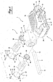
- the Figures 1 to 4 illustrate a first embodiment of a buffer device according to the invention, designated by the general reference 1 and intended to be fixed on the surface 2 of a support provided for example on a motor vehicle.
- the bumper device essentially comprises a housing 3 advantageously, in any suitable material, for example plastic material or steel, which is configured to enclose or encapsulate a bumper arrangement 4 and to be attached to the support surface 2 by means of, for example, four fasteners such as screws, whose through-holes 5 are provided on the rear end 6 of the housing.
- the stop arrangement 4 comprises a buffer buffer 8 mounted rotatably on an axis 9 whose ends 10 are retained in housing cavities 12 provided at the ends in the longitudinal direction of the housing, parallel to the axis 9, from and other a central opening 14 in the front end of the housing allowing the forward passage of a peripheral portion 16 of the roller 8.
- Each housing cavity 12 is open towards the rear and closed towards the front by a semicylindrical convex wall in the form of a cradle 18.
- These cradles 18 project forwardly above the front ends of the side walls. that is to say of the upper side wall 20 and the lower side wall 21 whose front edge 22 is curved so as to have a height in its central part, which is less than the height of its ends, while the upper wall 20 has a height at its ends which is lower than that of its remaining part.
- the projecting cradles are connected to the side walls 20 and 21 at their base by front wall portions 29.
- Each cradle 18 is closed at its outer axial end by the end side wall 26 of the housing.
- the U-shaped cradle is open and carried by column-shaped members 28 which extend perpendicularly to the rear end face and are connected at their foot by wall portions. 30 to the walls of the rear end of the housing, which include the passages 5 of the fixing screws.
- the housing has on both longitudinal sides of each cradle 18, between the columns thereof and the walls lateral 20 and 21 a free space above each wall portion 30, through which the fixing screws can be introduced into the support 2, through the holes 5, from the front end of the housing. More precisely, this zone of free access to the hole 5 is obtained by cuts in the connecting walls 29, above the rear wall zones 30, thus above the holes 5, at the level of the central opening 14 forward passage of the peripheral portion 16 of the roll 8.
- the casing has a generally parallelepipedal shape, hollow, rounded at the lateral ends and whose rear end is open and disengaged, with the exception of the connecting walls 30 while the front end is closed only at its lateral ends by curved walls before 32 cradles.
- the ends 10 of the axis 9 on which is rotatably mounted the roller 8, in the assembled state of the bumper device, are retained in the bottoms of the cradles 18, each by a helical spring 34 which extends perpendicularly from the support 2, via a stop guide 36 which comprises a cylindrical tubular portion 37 intended to engage axially in the spring and whose free outer end is in the form of a plate 38 with a diameter greater than diameter of the tubular portion 37 and which has a front face in relief, configured to have a recess 39 of complementary shape to the shape of the corresponding end of the axis 9 to support this end.
- the springs 34 push the ends 10 of the axis 9 into the bottom of the cradles 18 when the casing which encloses the bumper device 4 is fixed by fixing screws (not shown) on the support surface 2, the springs being compressed during this fixing.
- the rear ends of the springs bear directly against the surface 2.
- the figures 5 and 6 show a second embodiment according to which, during the assembly of the bumper device after the springs have been placed inside the housing, the springs housings are closed at the rear end of the housing, each by a circular closure plate 40, provided at the periphery, at diametrically opposite locations, with two fixing lugs 41, each traversed by a through hole 42 of a screw (not shown) for attachment to the rear end of the housing.
- the assembly of the bumper device is very simple, it suffices to introduce successively through the rear end of the housing, the axis 9 in the cradles 18 and the springs 34 in the receiving spaces below the cradles, after setting place in the springs the stop guides 36.
- the plates 40 are screwed onto the rear edge of the casing before the attachment of the stop device assembled on the support 2.
- the bumper roller 8 and the casing extend horizontally.
- the housing 3 extends vertically and encloses two relatively narrow buffer rollers 46, which are mounted in the housing, one above the other projecting forwardly through windows 48 in the front wall 49 of the housing. It is hollow and open at its rear end.
- the rollers 46 are rotatably mounted each on an axis 48 housed in a support 50 in the form of a frame formed by two parallel vertical walls 51 connected at their ends by a portion in the form of a perpendicular connecting flange 52 which extends vertically and is pierced by a hole 53.
- the frame has a shape complementary to the shape of the bumper housing so that it can be placed in the interior space thereof by being supported by these end flanges 52 on support lugs 54 provided in the front wall. 49 of the housing at the lateral ends thereof.
- These flanges 52 each have the function of constituting a bearing abutment of one end of a compression spring 56 whose other end is supported on a housing closure plate 58 which is intended to be attached to the rear the housing by fixing screws 60 at the upper and lower ends of the housing, to pass through holes 61.
- the walls 51 of the frame 50 are spaced from each other by a distance at least slightly greater than the outside diameter of the springs 56.
- the springs each engage an element tubular 62 which protrudes from the front wall 49 of the casing to the plate 58.
- the front wall being curved, it comprises at each lateral end a recessed wall portion, which is parallel to the plate 58 and constitutes the tab 54
- This comprises a hole 68 for passing a screw for fixing the housing to the support 2.
- the hole 68 is coaxial with the tubular element 62, the hole 52 of the support 50, the axis of the spring 56 and the corresponding hole 70 of the plate.
- the horizontal roller 8 of the first and second embodiments of the bumper rollers 8 are made either in the form of hollow cylindrical body or in the form of a "H" lying, slightly curved in the axial direction.
- the rollers 46 of the third embodiment have, in a diametral sectional view, above and below the passage of its axis 48 the profile of a coated H.
- the buffer device according to the invention has a very simple structure using only a small number of components, insofar as the bumper roller is rotating about an axis. which is supported by two springs so as to constitute a deformable support under a force and to damp the shocks suffered by the roller when in contact with an obstacle such as for example a dock or other element.
- the fact that the housing encapsulates the entire stop arrangement eliminates any risk of deterioration of the support in contact for example with a dock.
- An essential advantage of the invention lies in the fact that the proposed bumper device allows assembly of the device before its installation and that the installation of the pre-assembled device on its support is limited to the installation of only four accessible screws of the device. 'outside.
Landscapes
- Engineering & Computer Science (AREA)
- Mechanical Engineering (AREA)
- Vibration Dampers (AREA)
- Vibration Prevention Devices (AREA)
Claims (6)
- Anschlag- und Puffereinrichtung, die bestimmt ist, auf einem Halter (2) befestigt zu sein, der vor allem auf einem Fahrzeug vorgesehen, der Bauart, umfassend einen Aufnahmekörper mindestens einer zylindrischen Pufferrolle (8), die rotierend um eine Achse (9) senkrecht zu dieser Achse verlagerbar gegen Rückstellmittel (34) in dem Körper montiert ist, wobei der Körper ein hinteres Ende (6), das bestimmt ist, auf dem Halter (2) mit Befestigungselementen wie Schrauben, die durch Durchgangslöcher (5) gehen, und ein vorderes Ende, das eine Durchgangsöffnung (14) nach vorn eines Umfangsteils (16) der Rolle (8) aufweist, aufweist, wobei die Anschlag- und Puffereinrichtung vormontierbar ist und im vormontierten Zustand auf dem Halter (2) montiert ist und die Durchgangslöcher (5) der Befestigungselemente von außen ab dem vorderen Ende zugänglich sind, damit die Befestigungselemente in den Halter (2) durch die Löcher (5) ab diesem vorderen Ende einsetzbar sind, dadurch gekennzeichnet, dass der Aufnahmekörper in Form eines hohlen Gehäuses (3) realisiert ist, dass die Rückstellmittel von Rückstellfedern gebildet sind, die senkrecht zum hinteren Ende des Gehäuses ausgerichtet sind und auf denen die Enden (10) der Rotationsachse (9) ruhen, dass das hohle Gehäuse (3) derart konfiguriert ist, dass die Federn und die Pufferrolle (8) eingekapselt sind und eine allgemein parallelepipedische Form aufweist, die an ihrem hinteren Ende (6) offen ist und an ihrem vorderen Ende beiderseits der Durchgangsöffnung (14) des Umfangsteils (16) der Rolle (8) Wände (32) einer Aufnahmewiege (18) der Enden (10) der Rotationsachse (9) der Rolle aufweist, die jeweils auf einer Rückstellfeder ruhen.
- Anschlag- und Puffereinrichtung nach Anspruch 1, dadurch gekennzeichnet, dass sich die Wand (32) eine Wiege (18) bis zum hinteren Ende (6) des Gehäuses (3) anhand von Stützelementen (28) derart verlängert, dass der Raum zwischen der Wiege (18) und dem hinteren Ende einen Empfangsraum einer Feder (34) einer Stütze des Endes (10) der Achse (9) bildet, das in der Wiege ruht.
- Anschlag- und Puffereinrichtung nach Anspruch 2, dadurch gekennzeichnet, dass sich ein Ende (10) der Achse (9) auf einer Feder (34) mit Hilfe einer Anschlagführung (36) abstützt, die einen zylindrischen Teil (37) umfasst, der koaxial in die Feder eingreift, und an ihrem äußeren Ende mit Platte (38) mit einer Fläche ausgestattet ist, die ein Relief (39) aufweist, das zur Form des Endes (10) der Achse komplementär ist.
- Anschlag- und Puffereinrichtung nach Anspruch 3, dadurch gekennzeichnet, dass der Fuß der Stützstruktur (28) einer Wiege (18) mit der Seitenwand des Gehäuses (3) mit Hilfe eines Wandabschnitts (30) verbunden ist, der Durchgangslöcher (5) der Befestigungsschrauben auf dem Halter (2) der Anschlageinrichtung aufweist.
- Anschlageinrichtung nach einem der Ansprüche 1 bis 4, dadurch gekennzeichnet, dass jede Wiege (18) im Bereich ihrer Basis mit dem vorderen Rand jeder Seitenwand (20, 21) mit Hilfe eines vorderen Wandabschnitts (29) verbunden ist und dass die vorderen Wandabschnitte (29) in ihren Begrenzungsrändern der Rollendurchgangsöffnung (14) einen Ausschnitt über jeden Durchgangsloch (5) aufweisen, der den Zugang zu diesem Loch erlaubt.
- Anschlag- und Puffereinrichtung nach einem der Ansprüche 2 bis 5, dadurch gekennzeichnet, dass der Empfangsraum einer Feder (34), der von der Stützstruktur jeder Wiege (18) begrenzt ist, im Bereich des hinteren Endes (6) des Gehäuses mit einer Verschlussplatte (40) verschlossen ist, die mit Befestigungsmitteln auf den hinteren Rand des Gehäuses ausgestattet ist.
Priority Applications (1)
| Application Number | Priority Date | Filing Date | Title |
|---|---|---|---|
| PL13178278T PL2689971T3 (pl) | 2012-07-27 | 2013-07-26 | Urządzenie zderzakowe amortyzujące dla pojazdu, zwłaszcza dla pojazdu samochodowego |
Applications Claiming Priority (1)
| Application Number | Priority Date | Filing Date | Title |
|---|---|---|---|
| FR1257330A FR2993837B1 (fr) | 2012-07-27 | 2012-07-27 | Dispositif butoir amortisseur pour vehicule, notamment pour un vehicule automobile |
Publications (2)
| Publication Number | Publication Date |
|---|---|
| EP2689971A1 EP2689971A1 (de) | 2014-01-29 |
| EP2689971B1 true EP2689971B1 (de) | 2016-09-28 |
Family
ID=47022870
Family Applications (1)
| Application Number | Title | Priority Date | Filing Date |
|---|---|---|---|
| EP13178278.1A Active EP2689971B1 (de) | 2012-07-27 | 2013-07-26 | Puffereinrichtung für ein Fahrzeug, insbesondere für ein Kraftfahrzeug |
Country Status (5)
| Country | Link |
|---|---|
| EP (1) | EP2689971B1 (de) |
| ES (1) | ES2609009T3 (de) |
| FR (1) | FR2993837B1 (de) |
| PL (1) | PL2689971T3 (de) |
| PT (1) | PT2689971T (de) |
Family Cites Families (5)
| Publication number | Priority date | Publication date | Assignee | Title |
|---|---|---|---|---|
| FR2812254A1 (fr) * | 2000-07-28 | 2002-02-01 | Lamberet Const Isothermes | Butoir amortisseur pour vehicule accostant contre un quai |
| ITTV20020022U1 (it) * | 2002-06-04 | 2003-12-04 | Francesco Basso | Dispositivo paracolpi migliorato per ammortizzare gli urti fra mezzi di trasporto, banchine da carico e scarico, ingressi di magazzini e sim |
| FR2902057B1 (fr) * | 2006-06-08 | 2009-12-18 | Stephane Hubert | Tampon amortisseur de chocs notamment pour vehicule automobile |
| FR2914600B1 (fr) * | 2007-04-05 | 2009-09-11 | Reus Ingenierie Sarl | Butoir pour la protection d'un premier element lors de la rencontre avec un deuxieme element. |
| DE202011050555U1 (de) * | 2011-06-27 | 2011-10-20 | Kiesling Fahrzeugbau Gmbh | Rammpuffer |
-
2012
- 2012-07-27 FR FR1257330A patent/FR2993837B1/fr active Active
-
2013
- 2013-07-26 PT PT131782781T patent/PT2689971T/pt unknown
- 2013-07-26 PL PL13178278T patent/PL2689971T3/pl unknown
- 2013-07-26 ES ES13178278.1T patent/ES2609009T3/es active Active
- 2013-07-26 EP EP13178278.1A patent/EP2689971B1/de active Active
Also Published As
| Publication number | Publication date |
|---|---|
| FR2993837B1 (fr) | 2016-03-18 |
| PT2689971T (pt) | 2017-01-02 |
| PL2689971T3 (pl) | 2017-04-28 |
| EP2689971A1 (de) | 2014-01-29 |
| ES2609009T3 (es) | 2017-04-18 |
| FR2993837A1 (fr) | 2014-01-31 |
Similar Documents
| Publication | Publication Date | Title |
|---|---|---|
| EP0855301B1 (de) | Kassetten-Fensterhebemechanismus für Fahrzeugtür | |
| EP2726309B1 (de) | Seitenschutzvorrichtung für ein kraftfahrzeug und entsprechendes kraftfahrzeug | |
| EP1390639A1 (de) | Antischwingungslager und methode zur herstellung solcher | |
| EP2689971B1 (de) | Puffereinrichtung für ein Fahrzeug, insbesondere für ein Kraftfahrzeug | |
| EP2282076B1 (de) | Schwingungsdämpfervorrichtung für ein Fahrzeug, und eine solche Vorrichtung umfassendes Fahrzeug | |
| EP3429875B1 (de) | Fenster begleitungs vorrichtung für fahrzeugtür mit blockage in x richtung, gleitschuh, und korrespondierender tür und fahrzeug | |
| FR3051728A1 (fr) | Doublure interne de volet arriere | |
| FR2783368A1 (fr) | Dispositif perfectionne de fixation elastique d'un moteur electrique a bague, notamment pour vehicule automobile | |
| EP3600974A1 (de) | Airbagvorrichtung für innenauskleidungselement eines kraftfahrzeuges | |
| EP1449732B1 (de) | Versorgungseinrichtung für Bremssysteme, insbesondere für Kraftfahrzeuge sowie Verfahren zum Einbau eines solchen Systems | |
| FR2900124A1 (fr) | Boitier et ensemble prets a monter pour motocyclette, motocyclette correspondante et son procede de fabrication | |
| EP0741057A1 (de) | Ladagutabdeckung für eine Kraftfahrzeug | |
| EP3576423B1 (de) | Lautsprecher, der provisorische haltemittel vor der endgültigen befestigung auf einem aufnahmeteil umfasst | |
| EP1460004B1 (de) | Mit Laufrädern versehener Müllsammelbehälter | |
| FR2860760A1 (fr) | Tampon amortisseur de chocs notamment pour vehicule automoboile | |
| EP4444578B1 (de) | Beleuchtungseinrichtung für ein kraftfahrzeug | |
| FR3033764A1 (fr) | Dispositif formant marchepied d'un vehicule automobile | |
| EP2145815B1 (de) | Einheit aus einem Kotflügel und einem tragenden Element für Kraftfahrzeug | |
| EP1979192B1 (de) | Verfahren zur befestigung eines zubehörteils auf einem träger | |
| FR3144580A1 (fr) | Siège de véhicule et véhicule comportant un tel siège | |
| FR2917037A1 (fr) | Vehicule automobile comprenant des moyens de reprise d'efforts qui comportent un corps creux dans lequel est fixe un support de fixation d'une ceinture de securite | |
| FR3026368A1 (fr) | Agencement de rangement suspendu sous le pavillon d'un vehicule | |
| EP3515738B1 (de) | Gehäusesystem für traktionsbatterien eines hybrid- oder elektrofahrzeuges | |
| EP1568835A1 (de) | Begrenzungsanschlag für die Querverschiebung einer Schiebeglasscheibe einer Kraftfahrzeugtür | |
| EP2813387A1 (de) | Verbindungsgestänge zwischen zwei beweglichen Organen |
Legal Events
| Date | Code | Title | Description |
|---|---|---|---|
| PUAI | Public reference made under article 153(3) epc to a published international application that has entered the european phase |
Free format text: ORIGINAL CODE: 0009012 |
|
| AK | Designated contracting states |
Kind code of ref document: A1 Designated state(s): AL AT BE BG CH CY CZ DE DK EE ES FI FR GB GR HR HU IE IS IT LI LT LU LV MC MK MT NL NO PL PT RO RS SE SI SK SM TR |
|
| AX | Request for extension of the european patent |
Extension state: BA ME |
|
| 17P | Request for examination filed |
Effective date: 20140728 |
|
| RBV | Designated contracting states (corrected) |
Designated state(s): AL AT BE BG CH CY CZ DE DK EE ES FI FR GB GR HR HU IE IS IT LI LT LU LV MC MK MT NL NO PL PT RO RS SE SI SK SM TR |
|
| 17Q | First examination report despatched |
Effective date: 20141024 |
|
| GRAP | Despatch of communication of intention to grant a patent |
Free format text: ORIGINAL CODE: EPIDOSNIGR1 |
|
| INTG | Intention to grant announced |
Effective date: 20160418 |
|
| GRAS | Grant fee paid |
Free format text: ORIGINAL CODE: EPIDOSNIGR3 |
|
| GRAA | (expected) grant |
Free format text: ORIGINAL CODE: 0009210 |
|
| AK | Designated contracting states |
Kind code of ref document: B1 Designated state(s): AL AT BE BG CH CY CZ DE DK EE ES FI FR GB GR HR HU IE IS IT LI LT LU LV MC MK MT NL NO PL PT RO RS SE SI SK SM TR |
|
| REG | Reference to a national code |
Ref country code: GB Ref legal event code: FG4D Free format text: NOT ENGLISH |
|
| REG | Reference to a national code |
Ref country code: CH Ref legal event code: EP |
|
| REG | Reference to a national code |
Ref country code: AT Ref legal event code: REF Ref document number: 832442 Country of ref document: AT Kind code of ref document: T Effective date: 20161015 |
|
| REG | Reference to a national code |
Ref country code: IE Ref legal event code: FG4D Free format text: LANGUAGE OF EP DOCUMENT: FRENCH |
|
| REG | Reference to a national code |
Ref country code: DE Ref legal event code: R096 Ref document number: 602013012097 Country of ref document: DE |
|
| REG | Reference to a national code |
Ref country code: PT Ref legal event code: SC4A Ref document number: 2689971 Country of ref document: PT Date of ref document: 20170102 Kind code of ref document: T Free format text: AVAILABILITY OF NATIONAL TRANSLATION Effective date: 20161223 |
|
| REG | Reference to a national code |
Ref country code: NL Ref legal event code: FP |
|
| REG | Reference to a national code |
Ref country code: SE Ref legal event code: TRGR |
|
| REG | Reference to a national code |
Ref country code: LT Ref legal event code: MG4D |
|
| PG25 | Lapsed in a contracting state [announced via postgrant information from national office to epo] |
Ref country code: NO Free format text: LAPSE BECAUSE OF FAILURE TO SUBMIT A TRANSLATION OF THE DESCRIPTION OR TO PAY THE FEE WITHIN THE PRESCRIBED TIME-LIMIT Effective date: 20161228 Ref country code: RS Free format text: LAPSE BECAUSE OF FAILURE TO SUBMIT A TRANSLATION OF THE DESCRIPTION OR TO PAY THE FEE WITHIN THE PRESCRIBED TIME-LIMIT Effective date: 20160928 Ref country code: LT Free format text: LAPSE BECAUSE OF FAILURE TO SUBMIT A TRANSLATION OF THE DESCRIPTION OR TO PAY THE FEE WITHIN THE PRESCRIBED TIME-LIMIT Effective date: 20160928 Ref country code: HR Free format text: LAPSE BECAUSE OF FAILURE TO SUBMIT A TRANSLATION OF THE DESCRIPTION OR TO PAY THE FEE WITHIN THE PRESCRIBED TIME-LIMIT Effective date: 20160928 Ref country code: FI Free format text: LAPSE BECAUSE OF FAILURE TO SUBMIT A TRANSLATION OF THE DESCRIPTION OR TO PAY THE FEE WITHIN THE PRESCRIBED TIME-LIMIT Effective date: 20160928 |
|
| PG25 | Lapsed in a contracting state [announced via postgrant information from national office to epo] |
Ref country code: LV Free format text: LAPSE BECAUSE OF FAILURE TO SUBMIT A TRANSLATION OF THE DESCRIPTION OR TO PAY THE FEE WITHIN THE PRESCRIBED TIME-LIMIT Effective date: 20160928 Ref country code: GR Free format text: LAPSE BECAUSE OF FAILURE TO SUBMIT A TRANSLATION OF THE DESCRIPTION OR TO PAY THE FEE WITHIN THE PRESCRIBED TIME-LIMIT Effective date: 20161229 |
|
| REG | Reference to a national code |
Ref country code: SE Ref legal event code: RPOT |
|
| REG | Reference to a national code |
Ref country code: ES Ref legal event code: FG2A Ref document number: 2609009 Country of ref document: ES Kind code of ref document: T3 Effective date: 20170418 |
|
| PG25 | Lapsed in a contracting state [announced via postgrant information from national office to epo] |
Ref country code: EE Free format text: LAPSE BECAUSE OF FAILURE TO SUBMIT A TRANSLATION OF THE DESCRIPTION OR TO PAY THE FEE WITHIN THE PRESCRIBED TIME-LIMIT Effective date: 20160928 Ref country code: RO Free format text: LAPSE BECAUSE OF FAILURE TO SUBMIT A TRANSLATION OF THE DESCRIPTION OR TO PAY THE FEE WITHIN THE PRESCRIBED TIME-LIMIT Effective date: 20160928 |
|
| PG25 | Lapsed in a contracting state [announced via postgrant information from national office to epo] |
Ref country code: BG Free format text: LAPSE BECAUSE OF FAILURE TO SUBMIT A TRANSLATION OF THE DESCRIPTION OR TO PAY THE FEE WITHIN THE PRESCRIBED TIME-LIMIT Effective date: 20161228 Ref country code: CZ Free format text: LAPSE BECAUSE OF FAILURE TO SUBMIT A TRANSLATION OF THE DESCRIPTION OR TO PAY THE FEE WITHIN THE PRESCRIBED TIME-LIMIT Effective date: 20160928 Ref country code: SK Free format text: LAPSE BECAUSE OF FAILURE TO SUBMIT A TRANSLATION OF THE DESCRIPTION OR TO PAY THE FEE WITHIN THE PRESCRIBED TIME-LIMIT Effective date: 20160928 Ref country code: IS Free format text: LAPSE BECAUSE OF FAILURE TO SUBMIT A TRANSLATION OF THE DESCRIPTION OR TO PAY THE FEE WITHIN THE PRESCRIBED TIME-LIMIT Effective date: 20170128 Ref country code: SM Free format text: LAPSE BECAUSE OF FAILURE TO SUBMIT A TRANSLATION OF THE DESCRIPTION OR TO PAY THE FEE WITHIN THE PRESCRIBED TIME-LIMIT Effective date: 20160928 |
|
| REG | Reference to a national code |
Ref country code: DE Ref legal event code: R097 Ref document number: 602013012097 Country of ref document: DE |
|
| REG | Reference to a national code |
Ref country code: FR Ref legal event code: PLFP Year of fee payment: 5 |
|
| PG25 | Lapsed in a contracting state [announced via postgrant information from national office to epo] |
Ref country code: DK Free format text: LAPSE BECAUSE OF FAILURE TO SUBMIT A TRANSLATION OF THE DESCRIPTION OR TO PAY THE FEE WITHIN THE PRESCRIBED TIME-LIMIT Effective date: 20160928 |
|
| PLBE | No opposition filed within time limit |
Free format text: ORIGINAL CODE: 0009261 |
|
| STAA | Information on the status of an ep patent application or granted ep patent |
Free format text: STATUS: NO OPPOSITION FILED WITHIN TIME LIMIT |
|
| 26N | No opposition filed |
Effective date: 20170629 |
|
| PG25 | Lapsed in a contracting state [announced via postgrant information from national office to epo] |
Ref country code: SI Free format text: LAPSE BECAUSE OF FAILURE TO SUBMIT A TRANSLATION OF THE DESCRIPTION OR TO PAY THE FEE WITHIN THE PRESCRIBED TIME-LIMIT Effective date: 20160928 |
|
| REG | Reference to a national code |
Ref country code: CH Ref legal event code: PL |
|
| REG | Reference to a national code |
Ref country code: IE Ref legal event code: MM4A |
|
| PG25 | Lapsed in a contracting state [announced via postgrant information from national office to epo] |
Ref country code: IE Free format text: LAPSE BECAUSE OF NON-PAYMENT OF DUE FEES Effective date: 20170726 Ref country code: CH Free format text: LAPSE BECAUSE OF NON-PAYMENT OF DUE FEES Effective date: 20170731 Ref country code: LI Free format text: LAPSE BECAUSE OF NON-PAYMENT OF DUE FEES Effective date: 20170731 |
|
| PG25 | Lapsed in a contracting state [announced via postgrant information from national office to epo] |
Ref country code: LU Free format text: LAPSE BECAUSE OF NON-PAYMENT OF DUE FEES Effective date: 20170726 |
|
| REG | Reference to a national code |
Ref country code: FR Ref legal event code: PLFP Year of fee payment: 6 |
|
| PG25 | Lapsed in a contracting state [announced via postgrant information from national office to epo] |
Ref country code: MT Free format text: LAPSE BECAUSE OF FAILURE TO SUBMIT A TRANSLATION OF THE DESCRIPTION OR TO PAY THE FEE WITHIN THE PRESCRIBED TIME-LIMIT Effective date: 20160928 |
|
| PG25 | Lapsed in a contracting state [announced via postgrant information from national office to epo] |
Ref country code: AL Free format text: LAPSE BECAUSE OF FAILURE TO SUBMIT A TRANSLATION OF THE DESCRIPTION OR TO PAY THE FEE WITHIN THE PRESCRIBED TIME-LIMIT Effective date: 20160928 |
|
| REG | Reference to a national code |
Ref country code: AT Ref legal event code: UEP Ref document number: 832442 Country of ref document: AT Kind code of ref document: T Effective date: 20160928 |
|
| PG25 | Lapsed in a contracting state [announced via postgrant information from national office to epo] |
Ref country code: MC Free format text: LAPSE BECAUSE OF FAILURE TO SUBMIT A TRANSLATION OF THE DESCRIPTION OR TO PAY THE FEE WITHIN THE PRESCRIBED TIME-LIMIT Effective date: 20160928 Ref country code: HU Free format text: LAPSE BECAUSE OF FAILURE TO SUBMIT A TRANSLATION OF THE DESCRIPTION OR TO PAY THE FEE WITHIN THE PRESCRIBED TIME-LIMIT; INVALID AB INITIO Effective date: 20130726 |
|
| PG25 | Lapsed in a contracting state [announced via postgrant information from national office to epo] |
Ref country code: CY Free format text: LAPSE BECAUSE OF NON-PAYMENT OF DUE FEES Effective date: 20160928 |
|
| PGFP | Annual fee paid to national office [announced via postgrant information from national office to epo] |
Ref country code: PT Payment date: 20190712 Year of fee payment: 7 |
|
| PG25 | Lapsed in a contracting state [announced via postgrant information from national office to epo] |
Ref country code: MK Free format text: LAPSE BECAUSE OF FAILURE TO SUBMIT A TRANSLATION OF THE DESCRIPTION OR TO PAY THE FEE WITHIN THE PRESCRIBED TIME-LIMIT Effective date: 20160928 |
|
| PGFP | Annual fee paid to national office [announced via postgrant information from national office to epo] |
Ref country code: BE Payment date: 20190729 Year of fee payment: 7 |
|
| REG | Reference to a national code |
Ref country code: BE Ref legal event code: MM Effective date: 20200731 |
|
| PG25 | Lapsed in a contracting state [announced via postgrant information from national office to epo] |
Ref country code: PT Free format text: LAPSE BECAUSE OF NON-PAYMENT OF DUE FEES Effective date: 20210301 |
|
| PG25 | Lapsed in a contracting state [announced via postgrant information from national office to epo] |
Ref country code: BE Free format text: LAPSE BECAUSE OF NON-PAYMENT OF DUE FEES Effective date: 20200731 |
|
| P01 | Opt-out of the competence of the unified patent court (upc) registered |
Effective date: 20230518 |
|
| PGFP | Annual fee paid to national office [announced via postgrant information from national office to epo] |
Ref country code: PL Payment date: 20250630 Year of fee payment: 13 |
|
| PGFP | Annual fee paid to national office [announced via postgrant information from national office to epo] |
Ref country code: NL Payment date: 20250724 Year of fee payment: 13 |
|
| PGFP | Annual fee paid to national office [announced via postgrant information from national office to epo] |
Ref country code: ES Payment date: 20250801 Year of fee payment: 13 |
|
| PGFP | Annual fee paid to national office [announced via postgrant information from national office to epo] |
Ref country code: DE Payment date: 20250730 Year of fee payment: 13 |
|
| PGFP | Annual fee paid to national office [announced via postgrant information from national office to epo] |
Ref country code: TR Payment date: 20250722 Year of fee payment: 13 Ref country code: IT Payment date: 20250729 Year of fee payment: 13 |
|
| PGFP | Annual fee paid to national office [announced via postgrant information from national office to epo] |
Ref country code: GB Payment date: 20250725 Year of fee payment: 13 |
|
| PGFP | Annual fee paid to national office [announced via postgrant information from national office to epo] |
Ref country code: AT Payment date: 20250721 Year of fee payment: 13 Ref country code: FR Payment date: 20250710 Year of fee payment: 13 |
|
| PGFP | Annual fee paid to national office [announced via postgrant information from national office to epo] |
Ref country code: SE Payment date: 20250729 Year of fee payment: 13 |