EP2690331B1 - Soupape magnétique - Google Patents
Soupape magnétique Download PDFInfo
- Publication number
- EP2690331B1 EP2690331B1 EP20130002662 EP13002662A EP2690331B1 EP 2690331 B1 EP2690331 B1 EP 2690331B1 EP 20130002662 EP20130002662 EP 20130002662 EP 13002662 A EP13002662 A EP 13002662A EP 2690331 B1 EP2690331 B1 EP 2690331B1
- Authority
- EP
- European Patent Office
- Prior art keywords
- solenoid valve
- pole core
- armature
- valve according
- sleeve
- Prior art date
- Legal status (The legal status is an assumption and is not a legal conclusion. Google has not performed a legal analysis and makes no representation as to the accuracy of the status listed.)
- Active
Links
Images

Classifications
-
- F—MECHANICAL ENGINEERING; LIGHTING; HEATING; WEAPONS; BLASTING
- F16—ENGINEERING ELEMENTS AND UNITS; GENERAL MEASURES FOR PRODUCING AND MAINTAINING EFFECTIVE FUNCTIONING OF MACHINES OR INSTALLATIONS; THERMAL INSULATION IN GENERAL
- F16K—VALVES; TAPS; COCKS; ACTUATING-FLOATS; DEVICES FOR VENTING OR AERATING
- F16K31/00—Actuating devices; Operating means; Releasing devices
- F16K31/02—Actuating devices; Operating means; Releasing devices electric; magnetic
- F16K31/06—Actuating devices; Operating means; Releasing devices electric; magnetic using a magnet, e.g. diaphragm valves, cutting off by means of a liquid
- F16K31/0675—Electromagnet aspects, e.g. electric supply therefor
-
- F—MECHANICAL ENGINEERING; LIGHTING; HEATING; WEAPONS; BLASTING
- F16—ENGINEERING ELEMENTS AND UNITS; GENERAL MEASURES FOR PRODUCING AND MAINTAINING EFFECTIVE FUNCTIONING OF MACHINES OR INSTALLATIONS; THERMAL INSULATION IN GENERAL
- F16K—VALVES; TAPS; COCKS; ACTUATING-FLOATS; DEVICES FOR VENTING OR AERATING
- F16K31/00—Actuating devices; Operating means; Releasing devices
- F16K31/02—Actuating devices; Operating means; Releasing devices electric; magnetic
- F16K31/06—Actuating devices; Operating means; Releasing devices electric; magnetic using a magnet, e.g. diaphragm valves, cutting off by means of a liquid
- F16K31/0644—One-way valve
- F16K31/0655—Lift valves
-
- H—ELECTRICITY
- H01—ELECTRIC ELEMENTS
- H01F—MAGNETS; INDUCTANCES; TRANSFORMERS; SELECTION OF MATERIALS FOR THEIR MAGNETIC PROPERTIES
- H01F7/00—Magnets
- H01F7/06—Electromagnets; Actuators including electromagnets
- H01F7/08—Electromagnets; Actuators including electromagnets with armatures
- H01F7/16—Rectilinearly-movable armatures
- H01F7/1607—Armatures entering the winding
Definitions
- the present invention relates to a solenoid valve having a housing in which an axially displaceably mounted armature is arranged, which cooperates with a pole core.
- solenoid valves are well known. They can generally be used for leak-free, direct control of consumers.
- the problem with these solenoid valves is that the size of the air gap between armature and pole core varies due to component tolerances. The fluctuating air gap leads to a large dispersion of the magnetic force and thus to a high or too low contact force between the sealing body and the valve seat. On the one hand, this can lead to damage of the valve or, on the other hand, to leaks. Furthermore, magnetic field scattering of the coils can also be compensated.
- the armature is arranged in a sleeve connected to the pole core.
- the armature is movable in the sleeve, with the setting of the magnetic force is particularly simple.
- the pole core is preferably screwed via a thread (also: pitch thread) with a housing of the solenoid valve or an insert in the housing.
- the thread is self-locking and / or formed with a small pitch.
- the slope is preferably at most 1 mm, more preferably at most 0.5mm.
- the solution according to the invention has the advantage that with simple means damage to the valve can be avoided by excessive contact forces between the sealing body and the valve seat by the air gap between the pole core and the anchor set to a defined level and thus the respective required magnetic force exactly can be adjusted.
- an optimum operating gap dimension for the air gap can be adjusted in order to compensate for component tolerances and to transmit a maximum force.
- the sleeve is advantageously provided with a protruding from the housing approach for the attack of a tool.
- the air gap between the pole core and armature and thus the force acting on the armature magnetic force can be changed or adjusted quickly and easily, without the system must be opened.
- the pole core is provided with a central longitudinal bore in which a valve stem is guided, which is acted upon by the anchor.
- valve stem advantageously cooperates with a valve seat, which is arranged in a valve sleeve.
- valve sleeve In order to easily replace the valve sleeve, this is advantageously screwed into the housing.
- valve seat is pressed into the valve sleeve in order to receive valve seats with larger and smaller bores or different valve geometries in a uniform valve sleeve.
- a larger hole means a smaller locking or holding pressure with the same force and a smaller bore a larger locking or holding pressure at the same force.
- a replaceable filter is also arranged to use filters with different mesh sizes as needed.
- the pole core is surrounded by a steel disc in the region of the end facing the valve sleeve, a sufficiently large magnetic field can be built up, so that the housing can also consist of a non-magnetic material, such as aluminum.
- the entire solenoid valve is advantageously modular and may include, for example, hydraulic block, valve sleeve and magnet unit as a separate and interchangeable module.
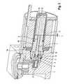
- the solenoid valve according to the invention has a housing 1, in which a valve sleeve 2 is screwed.
- a valve seat 3 is pressed with a through hole 4.
- a replaceable filter 5 is screwed or pressed into the valve sleeve 2.
- the through hole 4 On the rear side in the flow direction of the through hole 4, the through hole 4 is closed with a ball 6, which is mounted in a valve stem 7.
- the valve stem 7 is pushed away by a spring 8 of the valve sleeve 2 and is thus biased in the direction of the open position of the solenoid valve.
- the valve stem 7 extends through a central longitudinal bore 9 of a pole core 10, which is connected to a sleeve 11.
- the storage of Polkern 10 and sleeve 11 in the housing 1 is selected as follows: The sleeve 11 and the pole core 10 can be rotated and moved together, since the sleeve 11 and the pole core 10 are positively and rotationally connected to each other, wherein the sleeve 11 and Polkern 10 existing unit is rotatably and slidably held in the housing 1.
- the pole core 10 is screwed to the housing 1 via a thread 15 (also: pitch thread).
- the thread 15 is self-locking and allows a displacement of the pole core 10 relative to the housing 1 and relative to the housing-fixed valve sleeve. 2
- an armature 12 is slidably mounted on the side facing away from the valve sleeve 2 of the pole core 10.
- the valve stem 7 is slightly in the direction of the armature 12 via the pole core 10 to ensure that pole core 10 and armature 12 do not touch in the energized state, so as to avoid a pole short circuit.
- the sleeve 11 is provided with a protruding from the housing 1 approach 13, on which an intervention possibility for a tool, such as a wrench, is present.
- the entire solenoid valve may be modular and contain, for example, hydraulic block, valve sleeve and magnet unit as each independent and interchangeable module.
- FIG. 1 the solenoid valve is shown energized.
- the armature 12 is pulled in the direction of the pole core 10 and presses the valve stem 7 against the force of the spring 8 in the direction of the valve seat 3.
- the valve stem 7 in turn pushes the ball 6 mounted in it against the valve seat 3 and thus seals the through hole 4 off.
- the solenoid valve is thus closed.
- the valve is designed as a ball seat valve, however, a configuration as a conical seat valve is conceivable.
- the magnetic force exerted by the pole core 10 on the armature 12 can be set in the energized state.
- valve tappet 7 protrudes slightly beyond the pole core 10 in the direction of the armature 12 in the energized state, in order to ensure that pole core 10 and armature 12 do not touch each other in the energized state.
- the lifting force of the armature 12 should not be transmitted to the pole core 10 by surface contact (pole short circuit) but to the projecting valve stem 7.
- the axial extent of this air gap L formed between the pole core 10 and the armature 12 has a direct influence on the size of the the pole core 10 on the armature 12 exerted magnetic force.
- the sleeve 11 is rotated in the energized state via a suitable tool.
- the pole core 10 moves - depending on the direction of rotation - to the armature 12 to or away from him and thus reduces or increases the air gap L and thus the on the armature 12 exerted magnetic force.
- the air gap L can be adjusted in the range of 0.2 to 0.5 mm.
- the solenoid valve according to the invention can preferably be used in conjunction with floor door closers, narrow integrated door closers and door drives use, wherein the adjustability of the solenoid valve described above in other valves such as in 3/2-way valves or 4/2-way valves can be implemented.
Landscapes
- Engineering & Computer Science (AREA)
- General Engineering & Computer Science (AREA)
- Physics & Mathematics (AREA)
- Electromagnetism (AREA)
- Mechanical Engineering (AREA)
- Power Engineering (AREA)
- Magnetically Actuated Valves (AREA)
Claims (14)
- Vanne magnétique, avec un boîtier (1) dans lequel est agencé une armature (12) qui est supportée de façon déplaçable et coopère avec un noyau de pôle (10), la force magnétique exercée par le noyau de pôle (10) sur l'armature (12) étant ajustable par l'intermédiaire d'une modification de la fente d'air (L) entre le noyau de pôle (10) et l'armature (12), caractérisée en ce que l'armature (12) est agencée dans un manchon (11) connecté au noyau de pôle (10) et en ce que la fente d'air (L) entre le noyau de pôle (10) et l'armature (12) se règle par rotation du manchon (11).
- Vanne magnétique selon la revendication 1, caractérisée en ce que le noyau de pôle (10) est connecté de façon réglable avec un boîtier (1) de la vanne magnétique par l'intermédiaire d'un filetage (15).
- Vanne magnétique selon l'une des revendications précédentes, caractérisée en ce que le manchon (11) et le noyau de pôle (10) sont reliés entre eux par la forme et de façon à résister à la rotation.
- Vanne magnétique selon la revendication 3, caractérisée en ce que le manchon (11) est pourvu d'une prolongation (13) projetant du boîtier (1) pour l'engrenage d'un outil.
- Vanne magnétique selon l'une des revendications 1 à 4, caractérisée en ce que le noyau de pôle (10) est pourvu d'un alésage longitudinal central (9) dans lequel une tige de vanne (7) est guidée qui peut être chargée par l'armature (12).
- Vanne magnétique selon la revendication 5, caractérisée en ce que la tige de vanne (7) coopère avec un siège de vanne (3) qui est agencé dans un manchon de vanne (2).
- Vanne magnétique selon la revendication 5, caractérisée en ce que le noyau de pôle (10) est connecté au manchon de vanne (2) par l'intermédiaire d'un ajustement avec jeu déplaçable par glissement.
- Vanne magnétique selon la revendication 5 ou 6, caractérisée en ce que le manchon de vanne (2) est vissé dans le boîtier (1).
- Vanne magnétique selon l'une des revendications 6 à 8, caractérisée en ce que le siège de vanne (3) est pressé dans le manchon de vanne (2).
- Vanne magnétique selon l'une des revendications 1 à 9, caractérisée en ce qu'un filtre échangeable est agencé dans le manchon de vanne (2).
- Vanne magnétique selon l'une des revendications 1 à 10, caractérisée en ce que, dans la région de l'extrémité orientée vers le manchon de vanne (2), le noyau de pôle (10) est entouré d'un disc en acier (14).
- Vanne magnétique selon l'une des revendications 1 à 11, caractérisée par une construction modulaire.
- Vanne magnétique selon l'une des revendications précédentes, caractérisée en ce que le noyau de pôle (10) est agencé de façon à résister à la rotation par rapport à un boîtier (1) par l'intermédiaire d'un joint.
- Vanne magnétique selon l'une des revendications précédentes, caractérisée en ce que la fente d'air (L) entre le noyau de pôle (10) et l'armature (12) est réglable dans la condition où la vanne magnétique est remplie de fluide.
Applications Claiming Priority (1)
| Application Number | Priority Date | Filing Date | Title |
|---|---|---|---|
| DE201210106683 DE102012106683A1 (de) | 2012-07-24 | 2012-07-24 | Magnetventil |
Publications (4)
| Publication Number | Publication Date |
|---|---|
| EP2690331A2 EP2690331A2 (fr) | 2014-01-29 |
| EP2690331A3 EP2690331A3 (fr) | 2014-03-12 |
| EP2690331B1 true EP2690331B1 (fr) | 2015-03-11 |
| EP2690331B8 EP2690331B8 (fr) | 2015-04-29 |
Family
ID=48470692
Family Applications (1)
| Application Number | Title | Priority Date | Filing Date |
|---|---|---|---|
| EP20130002662 Active EP2690331B8 (fr) | 2012-07-24 | 2013-05-22 | Soupape magnétique |
Country Status (3)
| Country | Link |
|---|---|
| EP (1) | EP2690331B8 (fr) |
| DE (1) | DE102012106683A1 (fr) |
| ES (1) | ES2538410T3 (fr) |
Families Citing this family (2)
| Publication number | Priority date | Publication date | Assignee | Title |
|---|---|---|---|---|
| DE102014109575A1 (de) * | 2014-07-09 | 2016-01-14 | Pierburg Gmbh & Co Kg | Elektromagnetventil für den Kfz-Bereich |
| DE102015116464A1 (de) | 2015-09-29 | 2017-03-30 | Voith Patent Gmbh | Elektromagnetischer Stellantrieb zur Ausführung einer linearen Bewegung |
Family Cites Families (3)
| Publication number | Priority date | Publication date | Assignee | Title |
|---|---|---|---|---|
| GB8619868D0 (en) * | 1986-08-15 | 1986-09-24 | Eaton Sa Monaco | Fluid valve |
| US5407174A (en) * | 1990-08-31 | 1995-04-18 | Puritan-Bennett Corporation | Proportional electropneumatic solenoid-controlled valve |
| DE10046939B4 (de) * | 2000-09-21 | 2004-08-26 | Woco Industrietechnik Gmbh | Tauchankersystem mit Anschlagdämpfung |
-
2012
- 2012-07-24 DE DE201210106683 patent/DE102012106683A1/de not_active Ceased
-
2013
- 2013-05-22 ES ES13002662.8T patent/ES2538410T3/es active Active
- 2013-05-22 EP EP20130002662 patent/EP2690331B8/fr active Active
Also Published As
| Publication number | Publication date |
|---|---|
| EP2690331B8 (fr) | 2015-04-29 |
| ES2538410T3 (es) | 2015-06-19 |
| EP2690331A2 (fr) | 2014-01-29 |
| EP2690331A3 (fr) | 2014-03-12 |
| DE102012106683A1 (de) | 2014-01-30 |
Similar Documents
| Publication | Publication Date | Title |
|---|---|---|
| DE102008051759B3 (de) | Rohrförmige Ventileinrichtung | |
| EP0951412B1 (fr) | Vanne magnetique | |
| EP2630016B1 (fr) | Électrovanne, système de freinage | |
| EP1986874B1 (fr) | Dispositif a soupape pour la modification manuelle du niveau d'un vehicule dote d'une suspension pneumatique | |
| DE102010031275B4 (de) | Magnetventil mit Formfeder | |
| EP2243979B1 (fr) | Amortisseur d'oscillations réglable doté d'une soupape de fonctionnement d'urgence | |
| DE10232554B4 (de) | Magnetventil für Nutzfahrzeuge mit Luftfederung | |
| EP2519428B1 (fr) | Électrovanne | |
| DE3708248A1 (de) | Wegeventil | |
| DE102008008801A1 (de) | Kugelhahn | |
| EP2690331B1 (fr) | Soupape magnétique | |
| EP2690327B1 (fr) | Distributeur hydraulique | |
| DE202017102260U1 (de) | Frostsicheres Ventil | |
| DE102014226623A1 (de) | Druckbegrenzungsventil und damit ausgestattete hydraulische Maschine | |
| EP3014111A1 (fr) | Soupape de régulation de pression présentant un guidage dans le corps de soupape | |
| EP3049701B1 (fr) | Système de soupape | |
| DE10027598A1 (de) | Ventil | |
| EP2469140B1 (fr) | Soupape | |
| EP1907252B1 (fr) | Dispositif d'electrovanne pour systeme de freinage de vehicule | |
| DE102005056039A1 (de) | Hydraulisches / pneumatisches Steuerventil mit Fail-Safe Funktion | |
| WO2008061719A1 (fr) | Électroaimant pour l'actionnement de soupapes | |
| DE2638393A1 (de) | Sperr- und ableitelement fuer ein in ruhestellung geschlossenes elektroventil mit drei oeffnungen | |
| DE10208996B4 (de) | Elektromagnetventil | |
| DE3839424A1 (de) | Mehrwegeventil, insbesondere elektromagnetisch betaetigtes ventil fuer ausbausteuerungen | |
| EP2484945B1 (fr) | Distributeur hydraulique doté d'un dispositif d'arrêt |
Legal Events
| Date | Code | Title | Description |
|---|---|---|---|
| PUAI | Public reference made under article 153(3) epc to a published international application that has entered the european phase |
Free format text: ORIGINAL CODE: 0009012 |
|
| AK | Designated contracting states |
Kind code of ref document: A2 Designated state(s): AL AT BE BG CH CY CZ DE DK EE ES FI FR GB GR HR HU IE IS IT LI LT LU LV MC MK MT NL NO PL PT RO RS SE SI SK SM TR |
|
| AX | Request for extension of the european patent |
Extension state: BA ME |
|
| PUAL | Search report despatched |
Free format text: ORIGINAL CODE: 0009013 |
|
| AK | Designated contracting states |
Kind code of ref document: A3 Designated state(s): AL AT BE BG CH CY CZ DE DK EE ES FI FR GB GR HR HU IE IS IT LI LT LU LV MC MK MT NL NO PL PT RO RS SE SI SK SM TR |
|
| AX | Request for extension of the european patent |
Extension state: BA ME |
|
| RIC1 | Information provided on ipc code assigned before grant |
Ipc: F16K 31/06 20060101AFI20140131BHEP |
|
| 17P | Request for examination filed |
Effective date: 20140912 |
|
| RBV | Designated contracting states (corrected) |
Designated state(s): AL AT BE BG CH CY CZ DE DK EE ES FI FR GB GR HR HU IE IS IT LI LT LU LV MC MK MT NL NO PL PT RO RS SE SI SK SM TR |
|
| GRAP | Despatch of communication of intention to grant a patent |
Free format text: ORIGINAL CODE: EPIDOSNIGR1 |
|
| INTG | Intention to grant announced |
Effective date: 20141114 |
|
| GRAS | Grant fee paid |
Free format text: ORIGINAL CODE: EPIDOSNIGR3 |
|
| GRAA | (expected) grant |
Free format text: ORIGINAL CODE: 0009210 |
|
| AK | Designated contracting states |
Kind code of ref document: B1 Designated state(s): AL AT BE BG CH CY CZ DE DK EE ES FI FR GB GR HR HU IE IS IT LI LT LU LV MC MK MT NL NO PL PT RO RS SE SI SK SM TR |
|
| REG | Reference to a national code |
Ref country code: GB Ref legal event code: FG4D Free format text: NOT ENGLISH |
|
| REG | Reference to a national code |
Ref country code: CH Ref legal event code: EP |
|
| RAP2 | Party data changed (patent owner data changed or rights of a patent transferred) |
Owner name: DORMA DEUTSCHLAND GMBH |
|
| REG | Reference to a national code |
Ref country code: IE Ref legal event code: FG4D Free format text: LANGUAGE OF EP DOCUMENT: GERMAN |
|
| REG | Reference to a national code |
Ref country code: DE Ref legal event code: R081 Ref document number: 502013000426 Country of ref document: DE Owner name: DORMAKABA DEUTSCHLAND GMBH, DE Free format text: FORMER OWNER: DORMA GMBH + CO. KG, 58256 ENNEPETAL, DE Ref country code: AT Ref legal event code: REF Ref document number: 715543 Country of ref document: AT Kind code of ref document: T Effective date: 20150415 |
|
| REG | Reference to a national code |
Ref country code: DE Ref legal event code: R096 Ref document number: 502013000426 Country of ref document: DE Effective date: 20150423 |
|
| REG | Reference to a national code |
Ref country code: ES Ref legal event code: FG2A Ref document number: 2538410 Country of ref document: ES Kind code of ref document: T3 Effective date: 20150619 |
|
| REG | Reference to a national code |
Ref country code: NL Ref legal event code: VDEP Effective date: 20150311 |
|
| REG | Reference to a national code |
Ref country code: NL Ref legal event code: VDEP Effective date: 20150311 |
|
| PG25 | Lapsed in a contracting state [announced via postgrant information from national office to epo] |
Ref country code: FI Free format text: LAPSE BECAUSE OF FAILURE TO SUBMIT A TRANSLATION OF THE DESCRIPTION OR TO PAY THE FEE WITHIN THE PRESCRIBED TIME-LIMIT Effective date: 20150311 Ref country code: NO Free format text: LAPSE BECAUSE OF FAILURE TO SUBMIT A TRANSLATION OF THE DESCRIPTION OR TO PAY THE FEE WITHIN THE PRESCRIBED TIME-LIMIT Effective date: 20150611 Ref country code: HR Free format text: LAPSE BECAUSE OF FAILURE TO SUBMIT A TRANSLATION OF THE DESCRIPTION OR TO PAY THE FEE WITHIN THE PRESCRIBED TIME-LIMIT Effective date: 20150311 Ref country code: SE Free format text: LAPSE BECAUSE OF FAILURE TO SUBMIT A TRANSLATION OF THE DESCRIPTION OR TO PAY THE FEE WITHIN THE PRESCRIBED TIME-LIMIT Effective date: 20150311 Ref country code: LT Free format text: LAPSE BECAUSE OF FAILURE TO SUBMIT A TRANSLATION OF THE DESCRIPTION OR TO PAY THE FEE WITHIN THE PRESCRIBED TIME-LIMIT Effective date: 20150311 |
|
| REG | Reference to a national code |
Ref country code: LT Ref legal event code: MG4D |
|
| PG25 | Lapsed in a contracting state [announced via postgrant information from national office to epo] |
Ref country code: RS Free format text: LAPSE BECAUSE OF FAILURE TO SUBMIT A TRANSLATION OF THE DESCRIPTION OR TO PAY THE FEE WITHIN THE PRESCRIBED TIME-LIMIT Effective date: 20150311 Ref country code: LV Free format text: LAPSE BECAUSE OF FAILURE TO SUBMIT A TRANSLATION OF THE DESCRIPTION OR TO PAY THE FEE WITHIN THE PRESCRIBED TIME-LIMIT Effective date: 20150311 Ref country code: GR Free format text: LAPSE BECAUSE OF FAILURE TO SUBMIT A TRANSLATION OF THE DESCRIPTION OR TO PAY THE FEE WITHIN THE PRESCRIBED TIME-LIMIT Effective date: 20150612 |
|
| PG25 | Lapsed in a contracting state [announced via postgrant information from national office to epo] |
Ref country code: NL Free format text: LAPSE BECAUSE OF FAILURE TO SUBMIT A TRANSLATION OF THE DESCRIPTION OR TO PAY THE FEE WITHIN THE PRESCRIBED TIME-LIMIT Effective date: 20150311 |
|
| PG25 | Lapsed in a contracting state [announced via postgrant information from national office to epo] |
Ref country code: PT Free format text: LAPSE BECAUSE OF FAILURE TO SUBMIT A TRANSLATION OF THE DESCRIPTION OR TO PAY THE FEE WITHIN THE PRESCRIBED TIME-LIMIT Effective date: 20150713 Ref country code: SK Free format text: LAPSE BECAUSE OF FAILURE TO SUBMIT A TRANSLATION OF THE DESCRIPTION OR TO PAY THE FEE WITHIN THE PRESCRIBED TIME-LIMIT Effective date: 20150311 Ref country code: RO Free format text: LAPSE BECAUSE OF FAILURE TO SUBMIT A TRANSLATION OF THE DESCRIPTION OR TO PAY THE FEE WITHIN THE PRESCRIBED TIME-LIMIT Effective date: 20150311 Ref country code: CZ Free format text: LAPSE BECAUSE OF FAILURE TO SUBMIT A TRANSLATION OF THE DESCRIPTION OR TO PAY THE FEE WITHIN THE PRESCRIBED TIME-LIMIT Effective date: 20150311 Ref country code: EE Free format text: LAPSE BECAUSE OF FAILURE TO SUBMIT A TRANSLATION OF THE DESCRIPTION OR TO PAY THE FEE WITHIN THE PRESCRIBED TIME-LIMIT Effective date: 20150311 |
|
| PG25 | Lapsed in a contracting state [announced via postgrant information from national office to epo] |
Ref country code: PL Free format text: LAPSE BECAUSE OF FAILURE TO SUBMIT A TRANSLATION OF THE DESCRIPTION OR TO PAY THE FEE WITHIN THE PRESCRIBED TIME-LIMIT Effective date: 20150311 Ref country code: IS Free format text: LAPSE BECAUSE OF FAILURE TO SUBMIT A TRANSLATION OF THE DESCRIPTION OR TO PAY THE FEE WITHIN THE PRESCRIBED TIME-LIMIT Effective date: 20150711 |
|
| REG | Reference to a national code |
Ref country code: DE Ref legal event code: R097 Ref document number: 502013000426 Country of ref document: DE |
|
| PLBE | No opposition filed within time limit |
Free format text: ORIGINAL CODE: 0009261 |
|
| STAA | Information on the status of an ep patent application or granted ep patent |
Free format text: STATUS: NO OPPOSITION FILED WITHIN TIME LIMIT |
|
| PG25 | Lapsed in a contracting state [announced via postgrant information from national office to epo] |
Ref country code: LU Free format text: LAPSE BECAUSE OF FAILURE TO SUBMIT A TRANSLATION OF THE DESCRIPTION OR TO PAY THE FEE WITHIN THE PRESCRIBED TIME-LIMIT Effective date: 20150522 Ref country code: MC Free format text: LAPSE BECAUSE OF FAILURE TO SUBMIT A TRANSLATION OF THE DESCRIPTION OR TO PAY THE FEE WITHIN THE PRESCRIBED TIME-LIMIT Effective date: 20150311 Ref country code: DK Free format text: LAPSE BECAUSE OF FAILURE TO SUBMIT A TRANSLATION OF THE DESCRIPTION OR TO PAY THE FEE WITHIN THE PRESCRIBED TIME-LIMIT Effective date: 20150311 |
|
| 26N | No opposition filed |
Effective date: 20151214 |
|
| REG | Reference to a national code |
Ref country code: IE Ref legal event code: MM4A |
|
| PG25 | Lapsed in a contracting state [announced via postgrant information from national office to epo] |
Ref country code: SI Free format text: LAPSE BECAUSE OF FAILURE TO SUBMIT A TRANSLATION OF THE DESCRIPTION OR TO PAY THE FEE WITHIN THE PRESCRIBED TIME-LIMIT Effective date: 20150311 |
|
| PG25 | Lapsed in a contracting state [announced via postgrant information from national office to epo] |
Ref country code: IE Free format text: LAPSE BECAUSE OF NON-PAYMENT OF DUE FEES Effective date: 20150522 |
|
| REG | Reference to a national code |
Ref country code: FR Ref legal event code: PLFP Year of fee payment: 4 |
|
| PG25 | Lapsed in a contracting state [announced via postgrant information from national office to epo] |
Ref country code: MT Free format text: LAPSE BECAUSE OF FAILURE TO SUBMIT A TRANSLATION OF THE DESCRIPTION OR TO PAY THE FEE WITHIN THE PRESCRIBED TIME-LIMIT Effective date: 20150311 |
|
| REG | Reference to a national code |
Ref country code: CH Ref legal event code: PL |
|
| PG25 | Lapsed in a contracting state [announced via postgrant information from national office to epo] |
Ref country code: LI Free format text: LAPSE BECAUSE OF NON-PAYMENT OF DUE FEES Effective date: 20160531 Ref country code: CH Free format text: LAPSE BECAUSE OF NON-PAYMENT OF DUE FEES Effective date: 20160531 |
|
| REG | Reference to a national code |
Ref country code: DE Ref legal event code: R082 Ref document number: 502013000426 Country of ref document: DE Representative=s name: BALDER IP LAW, S.L., ES Ref country code: DE Ref legal event code: R081 Ref document number: 502013000426 Country of ref document: DE Owner name: DORMAKABA DEUTSCHLAND GMBH, DE Free format text: FORMER OWNER: DORMA DEUTSCHLAND GMBH, 58256 ENNEPETAL, DE |
|
| REG | Reference to a national code |
Ref country code: FR Ref legal event code: PLFP Year of fee payment: 5 |
|
| PG25 | Lapsed in a contracting state [announced via postgrant information from national office to epo] |
Ref country code: BG Free format text: LAPSE BECAUSE OF FAILURE TO SUBMIT A TRANSLATION OF THE DESCRIPTION OR TO PAY THE FEE WITHIN THE PRESCRIBED TIME-LIMIT Effective date: 20150311 Ref country code: HU Free format text: LAPSE BECAUSE OF FAILURE TO SUBMIT A TRANSLATION OF THE DESCRIPTION OR TO PAY THE FEE WITHIN THE PRESCRIBED TIME-LIMIT; INVALID AB INITIO Effective date: 20130522 |
|
| PG25 | Lapsed in a contracting state [announced via postgrant information from national office to epo] |
Ref country code: CY Free format text: LAPSE BECAUSE OF FAILURE TO SUBMIT A TRANSLATION OF THE DESCRIPTION OR TO PAY THE FEE WITHIN THE PRESCRIBED TIME-LIMIT Effective date: 20150311 |
|
| PG25 | Lapsed in a contracting state [announced via postgrant information from national office to epo] |
Ref country code: BE Free format text: LAPSE BECAUSE OF NON-PAYMENT OF DUE FEES Effective date: 20150531 |
|
| PG25 | Lapsed in a contracting state [announced via postgrant information from national office to epo] |
Ref country code: TR Free format text: LAPSE BECAUSE OF FAILURE TO SUBMIT A TRANSLATION OF THE DESCRIPTION OR TO PAY THE FEE WITHIN THE PRESCRIBED TIME-LIMIT Effective date: 20150311 |
|
| REG | Reference to a national code |
Ref country code: ES Ref legal event code: PC2A Owner name: DORMAKABA DEUTSCHLAND GMBH Effective date: 20171004 |
|
| REG | Reference to a national code |
Ref country code: FR Ref legal event code: CD Owner name: DORMA DEUTSCHLAND GMBH, DE Effective date: 20171003 |
|
| REG | Reference to a national code |
Ref country code: FR Ref legal event code: PLFP Year of fee payment: 6 |
|
| PG25 | Lapsed in a contracting state [announced via postgrant information from national office to epo] |
Ref country code: SM Free format text: LAPSE BECAUSE OF FAILURE TO SUBMIT A TRANSLATION OF THE DESCRIPTION OR TO PAY THE FEE WITHIN THE PRESCRIBED TIME-LIMIT Effective date: 20150311 |
|
| PG25 | Lapsed in a contracting state [announced via postgrant information from national office to epo] |
Ref country code: MK Free format text: LAPSE BECAUSE OF FAILURE TO SUBMIT A TRANSLATION OF THE DESCRIPTION OR TO PAY THE FEE WITHIN THE PRESCRIBED TIME-LIMIT Effective date: 20150311 |
|
| PG25 | Lapsed in a contracting state [announced via postgrant information from national office to epo] |
Ref country code: AL Free format text: LAPSE BECAUSE OF FAILURE TO SUBMIT A TRANSLATION OF THE DESCRIPTION OR TO PAY THE FEE WITHIN THE PRESCRIBED TIME-LIMIT Effective date: 20150311 |
|
| REG | Reference to a national code |
Ref country code: AT Ref legal event code: MM01 Ref document number: 715543 Country of ref document: AT Kind code of ref document: T Effective date: 20180522 |
|
| PG25 | Lapsed in a contracting state [announced via postgrant information from national office to epo] |
Ref country code: AT Free format text: LAPSE BECAUSE OF NON-PAYMENT OF DUE FEES Effective date: 20180522 |
|
| PGFP | Annual fee paid to national office [announced via postgrant information from national office to epo] |
Ref country code: DE Payment date: 20250521 Year of fee payment: 13 |
|
| PGFP | Annual fee paid to national office [announced via postgrant information from national office to epo] |
Ref country code: GB Payment date: 20250521 Year of fee payment: 13 Ref country code: ES Payment date: 20250627 Year of fee payment: 13 |
|
| PGFP | Annual fee paid to national office [announced via postgrant information from national office to epo] |
Ref country code: IT Payment date: 20250527 Year of fee payment: 13 |
|
| PGFP | Annual fee paid to national office [announced via postgrant information from national office to epo] |
Ref country code: FR Payment date: 20250528 Year of fee payment: 13 |