EP2690349A1 - Lichtwellenleiter für eine Beleuchtungs- und/oder Signalisierungsvorrichtung eines Kraftfahrzeugs - Google Patents
Lichtwellenleiter für eine Beleuchtungs- und/oder Signalisierungsvorrichtung eines Kraftfahrzeugs Download PDFInfo
- Publication number
- EP2690349A1 EP2690349A1 EP13176438.3A EP13176438A EP2690349A1 EP 2690349 A1 EP2690349 A1 EP 2690349A1 EP 13176438 A EP13176438 A EP 13176438A EP 2690349 A1 EP2690349 A1 EP 2690349A1
- Authority
- EP
- European Patent Office
- Prior art keywords
- guide
- face
- coupler
- faces
- couplers
- Prior art date
- Legal status (The legal status is an assumption and is not a legal conclusion. Google has not performed a legal analysis and makes no representation as to the accuracy of the status listed.)
- Granted
Links
Images



Classifications
-
- F—MECHANICAL ENGINEERING; LIGHTING; HEATING; WEAPONS; BLASTING
- F21—LIGHTING
- F21S—NON-PORTABLE LIGHTING DEVICES; SYSTEMS THEREOF; VEHICLE LIGHTING DEVICES SPECIALLY ADAPTED FOR VEHICLE EXTERIORS
- F21S43/00—Signalling devices specially adapted for vehicle exteriors, e.g. brake lamps, direction indicator lights or reversing lights
- F21S43/10—Signalling devices specially adapted for vehicle exteriors, e.g. brake lamps, direction indicator lights or reversing lights characterised by the light source
- F21S43/13—Signalling devices specially adapted for vehicle exteriors, e.g. brake lamps, direction indicator lights or reversing lights characterised by the light source characterised by the type of light source
- F21S43/14—Light emitting diodes [LED]
-
- F—MECHANICAL ENGINEERING; LIGHTING; HEATING; WEAPONS; BLASTING
- F21—LIGHTING
- F21S—NON-PORTABLE LIGHTING DEVICES; SYSTEMS THEREOF; VEHICLE LIGHTING DEVICES SPECIALLY ADAPTED FOR VEHICLE EXTERIORS
- F21S41/00—Illuminating devices specially adapted for vehicle exteriors, e.g. headlamps
- F21S41/20—Illuminating devices specially adapted for vehicle exteriors, e.g. headlamps characterised by refractors, transparent cover plates, light guides or filters
- F21S41/24—Light guides
-
- F—MECHANICAL ENGINEERING; LIGHTING; HEATING; WEAPONS; BLASTING
- F21—LIGHTING
- F21S—NON-PORTABLE LIGHTING DEVICES; SYSTEMS THEREOF; VEHICLE LIGHTING DEVICES SPECIALLY ADAPTED FOR VEHICLE EXTERIORS
- F21S43/00—Signalling devices specially adapted for vehicle exteriors, e.g. brake lamps, direction indicator lights or reversing lights
- F21S43/20—Signalling devices specially adapted for vehicle exteriors, e.g. brake lamps, direction indicator lights or reversing lights characterised by refractors, transparent cover plates, light guides or filters
- F21S43/235—Light guides
- F21S43/236—Light guides characterised by the shape of the light guide
- F21S43/239—Light guides characterised by the shape of the light guide plate-shaped
-
- F—MECHANICAL ENGINEERING; LIGHTING; HEATING; WEAPONS; BLASTING
- F21—LIGHTING
- F21S—NON-PORTABLE LIGHTING DEVICES; SYSTEMS THEREOF; VEHICLE LIGHTING DEVICES SPECIALLY ADAPTED FOR VEHICLE EXTERIORS
- F21S43/00—Signalling devices specially adapted for vehicle exteriors, e.g. brake lamps, direction indicator lights or reversing lights
- F21S43/20—Signalling devices specially adapted for vehicle exteriors, e.g. brake lamps, direction indicator lights or reversing lights characterised by refractors, transparent cover plates, light guides or filters
- F21S43/235—Light guides
- F21S43/242—Light guides characterised by the emission area
- F21S43/243—Light guides characterised by the emission area emitting light from one or more of its extremities
-
- F—MECHANICAL ENGINEERING; LIGHTING; HEATING; WEAPONS; BLASTING
- F21—LIGHTING
- F21S—NON-PORTABLE LIGHTING DEVICES; SYSTEMS THEREOF; VEHICLE LIGHTING DEVICES SPECIALLY ADAPTED FOR VEHICLE EXTERIORS
- F21S43/00—Signalling devices specially adapted for vehicle exteriors, e.g. brake lamps, direction indicator lights or reversing lights
- F21S43/20—Signalling devices specially adapted for vehicle exteriors, e.g. brake lamps, direction indicator lights or reversing lights characterised by refractors, transparent cover plates, light guides or filters
- F21S43/235—Light guides
- F21S43/249—Light guides with two or more light sources being coupled into the light guide
-
- F—MECHANICAL ENGINEERING; LIGHTING; HEATING; WEAPONS; BLASTING
- F21—LIGHTING
- F21S—NON-PORTABLE LIGHTING DEVICES; SYSTEMS THEREOF; VEHICLE LIGHTING DEVICES SPECIALLY ADAPTED FOR VEHICLE EXTERIORS
- F21S43/00—Signalling devices specially adapted for vehicle exteriors, e.g. brake lamps, direction indicator lights or reversing lights
- F21S43/20—Signalling devices specially adapted for vehicle exteriors, e.g. brake lamps, direction indicator lights or reversing lights characterised by refractors, transparent cover plates, light guides or filters
- F21S43/26—Refractors, transparent cover plates, light guides or filters not provided in groups F21S43/235 - F21S43/255
-
- F—MECHANICAL ENGINEERING; LIGHTING; HEATING; WEAPONS; BLASTING
- F21—LIGHTING
- F21S—NON-PORTABLE LIGHTING DEVICES; SYSTEMS THEREOF; VEHICLE LIGHTING DEVICES SPECIALLY ADAPTED FOR VEHICLE EXTERIORS
- F21S43/00—Signalling devices specially adapted for vehicle exteriors, e.g. brake lamps, direction indicator lights or reversing lights
- F21S43/30—Signalling devices specially adapted for vehicle exteriors, e.g. brake lamps, direction indicator lights or reversing lights characterised by reflectors
- F21S43/31—Optical layout thereof
-
- F—MECHANICAL ENGINEERING; LIGHTING; HEATING; WEAPONS; BLASTING
- F21—LIGHTING
- F21S—NON-PORTABLE LIGHTING DEVICES; SYSTEMS THEREOF; VEHICLE LIGHTING DEVICES SPECIALLY ADAPTED FOR VEHICLE EXTERIORS
- F21S43/00—Signalling devices specially adapted for vehicle exteriors, e.g. brake lamps, direction indicator lights or reversing lights
- F21S43/40—Signalling devices specially adapted for vehicle exteriors, e.g. brake lamps, direction indicator lights or reversing lights characterised by the combination of reflectors and refractors
-
- G—PHYSICS
- G02—OPTICS
- G02B—OPTICAL ELEMENTS, SYSTEMS OR APPARATUS
- G02B6/00—Light guides; Structural details of arrangements comprising light guides and other optical elements, e.g. couplings
- G02B6/0001—Light guides; Structural details of arrangements comprising light guides and other optical elements, e.g. couplings specially adapted for lighting devices or systems
- G02B6/0011—Light guides; Structural details of arrangements comprising light guides and other optical elements, e.g. couplings specially adapted for lighting devices or systems the light guides being planar or of plate-like form
- G02B6/0013—Means for improving the coupling-in of light from the light source into the light guide
- G02B6/0015—Means for improving the coupling-in of light from the light source into the light guide provided on the surface of the light guide or in the bulk of it
- G02B6/0018—Redirecting means on the surface of the light guide
-
- G—PHYSICS
- G02—OPTICS
- G02B—OPTICAL ELEMENTS, SYSTEMS OR APPARATUS
- G02B6/00—Light guides; Structural details of arrangements comprising light guides and other optical elements, e.g. couplings
- G02B6/0001—Light guides; Structural details of arrangements comprising light guides and other optical elements, e.g. couplings specially adapted for lighting devices or systems
- G02B6/0011—Light guides; Structural details of arrangements comprising light guides and other optical elements, e.g. couplings specially adapted for lighting devices or systems the light guides being planar or of plate-like form
- G02B6/0013—Means for improving the coupling-in of light from the light source into the light guide
- G02B6/0015—Means for improving the coupling-in of light from the light source into the light guide provided on the surface of the light guide or in the bulk of it
- G02B6/002—Means for improving the coupling-in of light from the light source into the light guide provided on the surface of the light guide or in the bulk of it by shaping at least a portion of the light guide, e.g. with collimating, focussing or diverging surfaces
-
- G—PHYSICS
- G02—OPTICS
- G02B—OPTICAL ELEMENTS, SYSTEMS OR APPARATUS
- G02B6/00—Light guides; Structural details of arrangements comprising light guides and other optical elements, e.g. couplings
- G02B6/0001—Light guides; Structural details of arrangements comprising light guides and other optical elements, e.g. couplings specially adapted for lighting devices or systems
- G02B6/0011—Light guides; Structural details of arrangements comprising light guides and other optical elements, e.g. couplings specially adapted for lighting devices or systems the light guides being planar or of plate-like form
- G02B6/0033—Means for improving the coupling-out of light from the light guide
Definitions
- the invention relates to lighting and / or signaling devices for motor vehicles.
- the beam may appear heterogeneous or even discontinuous along the line.
- An object of the invention is to produce a beam in which the distribution of light is continuous and homogeneous along the beam profile, whether this profile is straight or curved.
- a light guide for a lighting and / or signaling device for a motor vehicle, which comprises at least one coupler having at least two input faces arranged so that, when a source of light is arranged at a predetermined point with respect to the coupler, for each of the input faces, all the rays of the source passing geometrically through the point and penetrating into the guide by the input face are refracted therein. parallel shots between them.
- the input faces have given this orientation to the rays penetrating into the guide, they can easily be oriented to produce at the output of the guide a homogeneous and continuous beam. It is then sufficient to produce in the guide such juxtaposed couplers to obtain a beam in which the distribution of light is continuous and homogeneous along the profile of the beam, that this profile is straight or curved.
- the coupler or at least one of the couplers is arranged so that the parallel planes associated with one of the input faces are parallel to those associated with the other input face.
- the coupler or at least one of the couplers is arranged so that the parallel planes associated with one of the input faces are inclined relative to those associated with the other input face.
- This arrangement is particularly advantageous because it allows the couplers to follow the curvature of the guide where appropriate and to produce a homogeneous and continuous beam including in the curved areas of the web.
- the guide further comprises at least two reflection faces and is arranged so that the refracted rays are directed directly to one of the reflection faces where they are reflected directly to an exit face of the guide.
- each input face is arranged, in at least one of the parallel planes, so as to distribute homogeneously on one of the reflection faces all the refracted rays in this plane.
- the shape of the input face can be chosen according to the dimensions of a light source so as to distribute homogeneously on the reflection face the light emitted by this source when it is placed at the predetermined point.
- the input face has, in at least one of the parallel planes, a shape comprising a point of inflection, for example in "S".
- the input face may have, in at least one of the parallel planes, a shape devoid of an inflection point such as a curve segment or a line segment.
- this entrance face must provide the orientation function of the above-mentioned rays, there is great freedom to conform this face and in particular to obtain the desired ray arrangement.
- each reflection face has a cylindrical shape.
- the reflection face has a generatrix in the form of a line segment and a director in the form of a polynomial segment, especially a parabolic segment.
- the director extends in a direction perpendicular to the tablecloth
- Such a reflection face makes it possible to make all the rays reflected by this face parallel to each other, which makes it possible to obtain a particularly homogeneous beam at the outlet of the guide.
- all the reflection faces extend at the same distance from an exit face of the guide.
- the coupler or at least one of the couplers forms a collimator.
- the coupler or at least one of the couplers has a lens arranged so that, when the source is available at the predetermined point, rays of the source arrive directly on the lens which transmits them directly to an exit face. of the guide.
- This lens makes it possible to receive a portion of the rays of the source which are not directed towards the input faces. This improves the efficiency of the system.
- the portion of the beam produced by the lens can be arranged to extend in continuity of the beam portions produced by the input faces, to thereby ensure the continuity of the beam.
- the rays of the source arriving directly on the lens y are refracted to be all directed parallel to a main axis of the coupler, in the direction of the exit face of the guide.
- the lens of the coupler is disposed between the two input faces.
- the lens has a convex shape seen from the predetermined point.
- the lens could be convex to improve homogeneity.
- the coupler or at least one of the couplers is arranged to produce at an outlet face of the guide a rectangular-shaped beam in a plane perpendicular to a main direction of the beam.
- the coupler or at least one of the couplers is arranged to produce at an output face of the guide a beam oriented in a main direction normal to this face or a plane tangent to this face.
- the coupler or at least one of the couplers is arranged to produce at an exit face of the guide a beam oriented in a principal direction inclined with respect to a normal to this face or to a plane tangent to this face.
- the couplers are at least two in number.
- Each of the couplers thus forms a part of the total beam produced by the guide and can be provided as many couplers as necessary.
- At least two of the couplers are identical to each other.
- a lighting and / or signaling device for a motor vehicle which comprises a light guide according to the invention and a source disposed at the predetermined point.
- the source and the guide are arranged so that a light intensity per unit area of a beam produced by the coupler or at least one of the couplers has at any point at least along a center line an output face of the guide a value between 80% and 120%, or even between 90% and 110%, of a mean value of this intensity along this line, this line being parallel to a main face of the guide or a plane tangent to that face.
- Such a particularly homogeneous beam can easily be obtained by suitably shaping the faces of the guide as well as the source.
- the source and the guide are arranged so that, on one side of Out of the guide, less than half the area of a section of the beam produced by the coupler, in a plane perpendicular to a main direction of the beam, comes from the lens.
- the portion of the beam produced by the lens remains in the minority relative to the rest of the beam.
- the lens therefore has a complementary transmission role. In this way, the generation of a "hot spot" at the center of the beam is avoided, that is to say of a point having a particularly high light intensity relative to the others.
- the source is a light emitting diode (LED).
- LED light emitting diode
- Another object according to the invention is a motor vehicle comprising a room and / or a lighting and / or signaling device according to the present invention.
- FIG. 1 An embodiment of a signaling device for motor vehicles according to the invention. It is understood that the invention is also applicable to lighting devices or to lighting and signaling devices for such vehicles.
- the device 2 comprises a light guide 4 and light sources 6 including in this case LEDs.
- the guide includes couplers 8 which are in this case seven in number, this number is not limiting so that it may be less than or greater than this value.
- the number of LEDs is identical to the number of couplers with which they are associated in a bijective way.
- the guide 4 has a general shape of cylindrical shaped sheet and has two main faces 10 locally parallel to each other so that the guide has a constant thickness. In the middle part of the guide, the two faces 10 are planar. The two lateral end portions of the guide are curved on the same side of the median portion to give it a generally U-shaped profile as shown in FIG. figure 3 . The faces 10 are respectively convex and concave.
- This is a guide in one piece made by molding a transparent plastic material.
- This is, for example, PMMA having a refractive index of 1.49 or a polycarbonate having a refractive index of 1.59.
- the guide has two fields each extending on the end portions and the middle portion and respectively forming an input field 12 and an output field 14.
- the couplers 8 form the input field and follow each other along the line. the latter from one to the other end of the guide.
- the coupler 8 has two main planar faces 10 formed by the main faces of the guide. It furthermore has two input faces 16, a lens 18 and two internal reflection faces 20. A face 22 has also been indicated in the drawings as extending from one end of the reflection faces to the other. 20. However, it results from the artificial isolation of the coupler with respect to the guide. Such a face does not exist in fact.
- An orthogonal reference point X, Y, Z is used here in which the X and Y directions are parallel to the faces 10 and the XY and XZ planes form two planes of symmetry of the coupler.
- the aforementioned faces here constitute the only faces of the coupler.
- the coupler has in this case a general shape of isosceles triangle in plan view. It has a notch or beak 24 opening the tip of the triangle opposite the base 22 of the latter. This notch is materialized by the two input faces 16 which extend opposite one another but diverging as they approach the tip.
- the lens 18 provides the junction between the two inner ends of the input faces 16. And the latter, at their outer ends, have a common edge with the respective reflection faces 20.
- the source 6 is arranged so that its geometric center extends to a predetermined point 26 situated opposite the two input faces 16 and the lens 18.
- the input faces 16 and the reflection faces 20 are constructed so as to produce the following effects on the light rays emitted by the source laid down in point 6.
- the luminous intensity of the source 6 varies in the XY plane as a function of the emission angle ⁇ with respect to the direction X.
- the input and output faces reflection are calculated so as to obtain as much as possible a homogeneous distribution of the light intensity in a direction parallel to the Y axis on the fictitious outlet face 22 and on the exit face 14 of the guide.
- a median line 30 parallel to the direction Y and extending on the face 22 or on the exit face of the guide, equidistant from the two main faces 10 is defined. It is made that a luminous intensity per unit area of the beam produced by the coupler has, at any point on this line at least, a value between 90% and 110% of an average value of this intensity along this line. In this way, a particularly homogeneous distribution of the light intensity along this line is obtained, as illustrated in FIG. figure 8 . Preferably, this property is also valid for all lines of this face parallel to the line 30.
- the reflection faces 20 are total reflection faces and have a cylindrical shape with a parabolic profile or close to a parabola in a plane parallel to the X and Y directions.
- the lens 18 makes it possible to receive the radiation from the source directed towards the exit face and which is not received by the input faces. This is what was illustrated on the figure 14 in relation to the variant embodiment.
- the rays of the source arriving directly on the lens are refracted to be all directed parallel to the X axis in the direction of the exit face of the guide.
- the portion of the beam produced by the lens thus ensures continuity with the two beam portions produced by the reflection faces 20.
- the focal point of the lens is located at point 6.
- the source and the guide are arranged so that less than half of the area of a section of the beam produced by the coupler, in a plane perpendicular to a main direction of the beam, comes from the lens.
- the coupler thus forms a collimator which generates at the outlet of the coupler a collimated beam of rectangular section in a plane perpendicular to the direction X which constitutes the direction of propagation of the beam.
- the distribution of the luminous intensity in the section is homogeneous according to the two directions Y and Z. It is observed here that, considering the path of the light rays explained above, none of these rays normally comes to strike one of the faces. main 10.
- the four couplers extending in the end portions of the guide are formed slightly differently in view of the curve of the web at these locations.
- Each of these couplers differs from those illustrated in Figures 4 to 10 in that the XY plane no longer forms a plane of symmetry.
- these two halves are inclined relative to each other as if the previous coupler had been modified by "turning" these two halves around an X axis hinge.
- these two halves are symmetrical to each other with respect to the plane XZ.
- the definition and properties of the input and reflection faces remain unchanged except that the parallel planes associated with one of the input faces are inclined relative to those associated with the other input face.
- these faces are now limited by curved portions of the main faces that intercept them.
- These curved couplers thus also produce beams which have in section in a plane parallel to the Y and Z directions a homogeneous and continuous distribution of light intensity, this section being this time curved.
- the input faces 16 are all identical to each other except for their limitation by the main faces 10. The same is true for the reflection faces 20.
- the thickness of the light guide is equal to the thickness of each of the couplers.
- the couplers are arranged so that the points 6 all extend at the same distance from the exit face 14. The same is true for the distance extending between this face and each reflection face 20. in this case the couplers are oriented in the direction of extrusion of the guide.
- a signaling device comprising several couplers of this type makes it possible to produce a beam 32 such as that illustrated in FIG. figure 11 which has a good continuity and a good homogeneity all along the lines that constitute it, in particular in the curved portions.
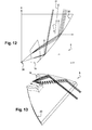
- the input and reflection faces are modified so that the rays reflected by the latter are oriented along the same main direction D before crossing the exit face, then following the same main direction D 'at the output of this face.
- These two directions D and D ' are inclined with respect to the axis X and written in a plane parallel to the directions X and Y.
- the direction D being inclined with respect to the axis X, the direction D' is even more given the refraction that occurs at the passage of the exit face.
- This variant makes it possible in particular to compensate for any inclination of the main axis of the light source relative to the axis X.
- the input face here has an "S" shape in a plane parallel to the X and Y directions to increase still the homogeneity of the luminous intensity. It presents here a profiled shape with a hyperbole profile.
- the guide may for example have a length and / or a width of between 25 and 35 mm.
- the invention is applicable to flat or curved light guides.
- exit face 14 has in this case a planar shape, we can give this face a curved shape in a plane or in two planes perpendicular to each other. It is therefore a plane tangent to this curved face and the normal direction to this plane that will then be considered to identify the orientation of the main beam of each coupler.
- each of the input faces and of the reflection faces portion by portion, without these faces having a simple overall shape or geometric definition, in order to give the beam produced by the coupler the desired properties.
Landscapes
- Engineering & Computer Science (AREA)
- Physics & Mathematics (AREA)
- General Engineering & Computer Science (AREA)
- Optics & Photonics (AREA)
- General Physics & Mathematics (AREA)
- Microelectronics & Electronic Packaging (AREA)
- Non-Portable Lighting Devices Or Systems Thereof (AREA)
- Planar Illumination Modules (AREA)
Applications Claiming Priority (1)
| Application Number | Priority Date | Filing Date | Title |
|---|---|---|---|
| FR1257136A FR2993633B1 (fr) | 2012-07-23 | 2012-07-23 | Guide de lumiere pour un dispositif d'eclairage et/ou de signalisation de vehicule automobile |
Publications (2)
| Publication Number | Publication Date |
|---|---|
| EP2690349A1 true EP2690349A1 (de) | 2014-01-29 |
| EP2690349B1 EP2690349B1 (de) | 2020-09-09 |
Family
ID=46889287
Family Applications (1)
| Application Number | Title | Priority Date | Filing Date |
|---|---|---|---|
| EP13176438.3A Active EP2690349B1 (de) | 2012-07-23 | 2013-07-15 | Lichtwellenleiter für eine Beleuchtungs- und/oder Signalisierungsvorrichtung eines Kraftfahrzeugs |
Country Status (4)
| Country | Link |
|---|---|
| US (1) | US9574731B2 (de) |
| EP (1) | EP2690349B1 (de) |
| CN (1) | CN103574515B (de) |
| FR (1) | FR2993633B1 (de) |
Families Citing this family (15)
| Publication number | Priority date | Publication date | Assignee | Title |
|---|---|---|---|---|
| WO2015013542A1 (en) | 2013-07-25 | 2015-01-29 | Bio-Rad Laboratories, Inc. | Enhanced functionality and delivery of a protein from a porous substrate |
| JP6587849B2 (ja) * | 2015-07-10 | 2019-10-09 | スタンレー電気株式会社 | 導光レンズ及び灯具 |
| FR3039629B1 (fr) * | 2015-07-28 | 2020-08-14 | Valeo Vision | Dispositif d'eclairage pour projecteur de vehicule automobile |
| CN106439735A (zh) | 2015-08-07 | 2017-02-22 | 法雷奥照明湖北技术中心有限公司 | 导光单元、光导装置以及照明和/或信号指示设备 |
| DE102015221672A1 (de) * | 2015-11-04 | 2017-05-04 | Hyundai Motor Company | Lichtleitermodul für eine Fahrzeuglampe und Verfahren zum Herstellen solch eines Lichtleitermoduls |
| DE102015222495A1 (de) | 2015-11-13 | 2017-05-18 | Automotive Lighting Reutlingen Gmbh | Vorsatzoptik und Vorsatzoptikanordnung mit mehreren Vorsatzoptiken |
| ITUB20156264A1 (it) * | 2015-12-04 | 2017-06-04 | Automotive Lighting Italia S P A A Socio Unico | Dispositivo di illuminazione per veicoli |
| CZ307412B6 (cs) | 2017-06-13 | 2018-08-01 | Varroc Lighting Systems, s.r.o. | Světlovodivý optický systém |
| CN108571700B (zh) * | 2017-11-06 | 2024-03-26 | 常州星宇车灯股份有限公司 | 一种利用全反射的光导结构及采用该光导结构的照明装置 |
| CZ307945B6 (cs) * | 2018-01-08 | 2019-09-04 | Hella Autotechnik Nova S.R.O. | Prostředek pro zajištění homogenity světelného svazku |
| CN110657399B (zh) * | 2018-06-29 | 2025-11-04 | 法雷奥市光(中国)车灯有限公司 | 配光构件、照明或信号指示装置和机动车辆 |
| US10962194B1 (en) * | 2019-12-14 | 2021-03-30 | Valeo North America, Inc. | Motor vehicle light guide and reflective coupler system for outboard homogenous lit appearance of lamp module |
| DE102022121364A1 (de) * | 2022-08-24 | 2024-02-29 | HELLA GmbH & Co. KGaA | Linse für den Einsatz in einem Mehrlinsensystem eines Scheinwerfers eines Kraftfahrzeugs |
| US20250306261A1 (en) * | 2024-03-28 | 2025-10-02 | Schneider Electric Industries Sas | Light guide and associated electrical device |
| FR3161485A1 (fr) * | 2024-03-28 | 2025-10-24 | Schneider Electric Industries Sas | Guide lumière et appareil électrique associé |
Citations (5)
| Publication number | Priority date | Publication date | Assignee | Title |
|---|---|---|---|---|
| US5700078A (en) * | 1996-12-23 | 1997-12-23 | Ford Global Technologies, Inc. | Laser illuminated lighting system |
| US20030235046A1 (en) * | 2002-06-25 | 2003-12-25 | Visteon Global Technologies, Inc. | Optical element and lamp assembly utilizing the same |
| EP2157363A2 (de) * | 2008-08-22 | 2010-02-24 | Magna International Inc. | Optisches Element für eine Fahrzeugleuchte |
| EP2354637A2 (de) * | 2010-01-30 | 2011-08-10 | Hella KGaA Hueck & Co. | Beleuchtungsvorrichtung für Fahrzeuge |
| EP2479486A2 (de) * | 2011-01-24 | 2012-07-25 | Stanley Electric Co., Ltd. | Fahrzeugsbeleuchtungseinheit |
Family Cites Families (8)
| Publication number | Priority date | Publication date | Assignee | Title |
|---|---|---|---|---|
| FR2836208B1 (fr) * | 2002-02-21 | 2004-09-03 | Valeo Vision | Feu de signalisation comportant une piece optique realisant une fonction de signalisation de maniere autonome |
| FR2846400B1 (fr) * | 2002-10-28 | 2005-10-07 | Valeo Vision | Feu de signalisation comportant un dispositif de recuperation et de repartition du flux lumineux vers un reflecteur annulaire |
| FR2853392B1 (fr) * | 2003-04-04 | 2006-06-16 | Sli Miniature Lighting Sa | Feu arriere, en particulier feu stop pour vehicule automobile |
| JP4300123B2 (ja) * | 2004-01-13 | 2009-07-22 | スタンレー電気株式会社 | 導光体を用いたled灯具 |
| FR2884899B1 (fr) * | 2005-04-21 | 2007-06-15 | Valeo Vision Sa | Module d'eclairage donnant un faisceau lumineux avec coupure pour projecteur de vehicule automobile, et projecteur comprenant un tel module |
| US7967477B2 (en) * | 2007-09-06 | 2011-06-28 | Philips Lumileds Lighting Company Llc | Compact optical system and lenses for producing uniform collimated light |
| FR2941785B1 (fr) * | 2009-02-05 | 2011-04-15 | Valeo Vision Sas | Dispositif optique, notamment pour vehicule automobile, tel qu'un dispositif d'eclairage ou de signalisation |
| WO2011021135A1 (en) * | 2009-08-19 | 2011-02-24 | Koninklijke Philips Electronics N.V. | A lighting device and a lens suitable for such a lighting device |
-
2012
- 2012-07-23 FR FR1257136A patent/FR2993633B1/fr not_active Expired - Fee Related
-
2013
- 2013-07-15 EP EP13176438.3A patent/EP2690349B1/de active Active
- 2013-07-18 CN CN201310302875.2A patent/CN103574515B/zh active Active
- 2013-07-19 US US13/946,254 patent/US9574731B2/en active Active
Patent Citations (5)
| Publication number | Priority date | Publication date | Assignee | Title |
|---|---|---|---|---|
| US5700078A (en) * | 1996-12-23 | 1997-12-23 | Ford Global Technologies, Inc. | Laser illuminated lighting system |
| US20030235046A1 (en) * | 2002-06-25 | 2003-12-25 | Visteon Global Technologies, Inc. | Optical element and lamp assembly utilizing the same |
| EP2157363A2 (de) * | 2008-08-22 | 2010-02-24 | Magna International Inc. | Optisches Element für eine Fahrzeugleuchte |
| EP2354637A2 (de) * | 2010-01-30 | 2011-08-10 | Hella KGaA Hueck & Co. | Beleuchtungsvorrichtung für Fahrzeuge |
| EP2479486A2 (de) * | 2011-01-24 | 2012-07-25 | Stanley Electric Co., Ltd. | Fahrzeugsbeleuchtungseinheit |
Also Published As
| Publication number | Publication date |
|---|---|
| US20140029284A1 (en) | 2014-01-30 |
| CN103574515B (zh) | 2019-04-16 |
| US9574731B2 (en) | 2017-02-21 |
| FR2993633A1 (fr) | 2014-01-24 |
| EP2690349B1 (de) | 2020-09-09 |
| CN103574515A (zh) | 2014-02-12 |
| FR2993633B1 (fr) | 2018-12-07 |
Similar Documents
| Publication | Publication Date | Title |
|---|---|---|
| EP2690349B1 (de) | Lichtwellenleiter für eine Beleuchtungs- und/oder Signalisierungsvorrichtung eines Kraftfahrzeugs | |
| FR2995977B1 (fr) | Guide de lumiere pour un dispositif d'eclairage et/ou de signalisation de vehicule automobile | |
| EP3128226B1 (de) | Leuchtmodul aus transparentem material mit zwei reflexionsseiten | |
| EP1857732B1 (de) | Vorrichtung zur Beleuchtung und/oder Signalisierung für Kraftfahrzeuge | |
| EP3124855B1 (de) | Beleuchtungsvorrichtung für kraftfahrzeugscheinwerfer | |
| EP2703852B1 (de) | Lichtleitungslage mit Eingangskoppelung und Diopter mit Fresnel-Oberfläche | |
| EP2679884A1 (de) | Optische Vorrichtung für Kraftfahrzeug mit im Lichtleiter integrierten dioptrischen Elementen | |
| EP1881265B1 (de) | Beleuchtungseinrichtung mit einer Lichtleiterplatte, die eine kreisbogenförmige, rückstrahlende Reflexionsfläche aufweist | |
| EP3273149B1 (de) | Leuchtmodul für kraftfahrzeuge | |
| FR2966224A1 (fr) | Dispositif d'eclairage ou de signalisation | |
| EP3014175B1 (de) | Beleuchtungsvorrichtung | |
| FR2943400A1 (fr) | Dispositif d'eclairage ou de signalisation pour vehicule automobile | |
| EP2999919B1 (de) | Optischer wellenleiter mit einem reflektierenden muster zur verbreitung eines lichtstrahls | |
| EP0838628B1 (de) | Kraftfahrzeug- Scheinwerfer mit einem Lichtleiter | |
| FR2902494A1 (fr) | Dispositif d'eclairage ou de signalisation a guide optique pour vehicule automobile | |
| EP2711610A1 (de) | Vorrichtung zur Beleuchtung und/oder Signalisierung, insbesondere für Kraftfahrzeuge | |
| FR3050010A1 (fr) | Module d'emission de lumiere compact, dispositif et projecteur associes pour vehicule automobile | |
| EP1739468B1 (de) | Beleuchtungs- oder Signalvorrichtung für Kraftfahrzeuge | |
| EP4078025B1 (de) | Lichtleiter mit teilweise kollimierender eingangsfläche | |
| FR3009065A1 (fr) | Dispositif optique de vehicule automobile | |
| FR3031815A1 (fr) | Guide de lumiere avec une partie courbee vers l'arriere et dispositif lumineux le comprenant | |
| FR2918441A1 (fr) | Projecteur de vehicule | |
| FR2916832A1 (fr) | Dispositif de couplage optique entre au moins une source et une guide de lumiere, et dispositif de signalisation et/ou d'eclairage pour vehicule automobile | |
| EP2846080A1 (de) | Lichtführung für eine Beleuchtungs- und/oder Lichtsignalgebungsvorrichtung für Kraftfahrzeug |
Legal Events
| Date | Code | Title | Description |
|---|---|---|---|
| PUAI | Public reference made under article 153(3) epc to a published international application that has entered the european phase |
Free format text: ORIGINAL CODE: 0009012 |
|
| AK | Designated contracting states |
Kind code of ref document: A1 Designated state(s): AL AT BE BG CH CY CZ DE DK EE ES FI FR GB GR HR HU IE IS IT LI LT LU LV MC MK MT NL NO PL PT RO RS SE SI SK SM TR |
|
| AX | Request for extension of the european patent |
Extension state: BA ME |
|
| 17P | Request for examination filed |
Effective date: 20140710 |
|
| RBV | Designated contracting states (corrected) |
Designated state(s): AL AT BE BG CH CY CZ DE DK EE ES FI FR GB GR HR HU IE IS IT LI LT LU LV MC MK MT NL NO PL PT RO RS SE SI SK SM TR |
|
| REG | Reference to a national code |
Ref country code: DE Ref legal event code: R079 Ref document number: 602013072321 Country of ref document: DE Free format text: PREVIOUS MAIN CLASS: F21S0008100000 Ipc: F21S0041240000 |
|
| RIC1 | Information provided on ipc code assigned before grant |
Ipc: F21S 43/14 20180101ALI20200304BHEP Ipc: G02B 6/00 20060101ALI20200304BHEP Ipc: F21S 41/24 20180101AFI20200304BHEP Ipc: F21V 8/00 20060101ALI20200304BHEP |
|
| GRAP | Despatch of communication of intention to grant a patent |
Free format text: ORIGINAL CODE: EPIDOSNIGR1 |
|
| STAA | Information on the status of an ep patent application or granted ep patent |
Free format text: STATUS: GRANT OF PATENT IS INTENDED |
|
| INTG | Intention to grant announced |
Effective date: 20200421 |
|
| GRAS | Grant fee paid |
Free format text: ORIGINAL CODE: EPIDOSNIGR3 |
|
| GRAA | (expected) grant |
Free format text: ORIGINAL CODE: 0009210 |
|
| STAA | Information on the status of an ep patent application or granted ep patent |
Free format text: STATUS: THE PATENT HAS BEEN GRANTED |
|
| AK | Designated contracting states |
Kind code of ref document: B1 Designated state(s): AL AT BE BG CH CY CZ DE DK EE ES FI FR GB GR HR HU IE IS IT LI LT LU LV MC MK MT NL NO PL PT RO RS SE SI SK SM TR |
|
| REG | Reference to a national code |
Ref country code: GB Ref legal event code: FG4D Free format text: NOT ENGLISH |
|
| REG | Reference to a national code |
Ref country code: AT Ref legal event code: REF Ref document number: 1312015 Country of ref document: AT Kind code of ref document: T Effective date: 20200915 Ref country code: CH Ref legal event code: EP |
|
| REG | Reference to a national code |
Ref country code: IE Ref legal event code: FG4D Free format text: LANGUAGE OF EP DOCUMENT: FRENCH |
|
| REG | Reference to a national code |
Ref country code: DE Ref legal event code: R096 Ref document number: 602013072321 Country of ref document: DE |
|
| REG | Reference to a national code |
Ref country code: LT Ref legal event code: MG4D |
|
| PG25 | Lapsed in a contracting state [announced via postgrant information from national office to epo] |
Ref country code: GR Free format text: LAPSE BECAUSE OF FAILURE TO SUBMIT A TRANSLATION OF THE DESCRIPTION OR TO PAY THE FEE WITHIN THE PRESCRIBED TIME-LIMIT Effective date: 20201210 Ref country code: LT Free format text: LAPSE BECAUSE OF FAILURE TO SUBMIT A TRANSLATION OF THE DESCRIPTION OR TO PAY THE FEE WITHIN THE PRESCRIBED TIME-LIMIT Effective date: 20200909 Ref country code: FI Free format text: LAPSE BECAUSE OF FAILURE TO SUBMIT A TRANSLATION OF THE DESCRIPTION OR TO PAY THE FEE WITHIN THE PRESCRIBED TIME-LIMIT Effective date: 20200909 Ref country code: HR Free format text: LAPSE BECAUSE OF FAILURE TO SUBMIT A TRANSLATION OF THE DESCRIPTION OR TO PAY THE FEE WITHIN THE PRESCRIBED TIME-LIMIT Effective date: 20200909 Ref country code: SE Free format text: LAPSE BECAUSE OF FAILURE TO SUBMIT A TRANSLATION OF THE DESCRIPTION OR TO PAY THE FEE WITHIN THE PRESCRIBED TIME-LIMIT Effective date: 20200909 Ref country code: BG Free format text: LAPSE BECAUSE OF FAILURE TO SUBMIT A TRANSLATION OF THE DESCRIPTION OR TO PAY THE FEE WITHIN THE PRESCRIBED TIME-LIMIT Effective date: 20201209 Ref country code: NO Free format text: LAPSE BECAUSE OF FAILURE TO SUBMIT A TRANSLATION OF THE DESCRIPTION OR TO PAY THE FEE WITHIN THE PRESCRIBED TIME-LIMIT Effective date: 20201209 |
|
| REG | Reference to a national code |
Ref country code: AT Ref legal event code: MK05 Ref document number: 1312015 Country of ref document: AT Kind code of ref document: T Effective date: 20200909 |
|
| REG | Reference to a national code |
Ref country code: NL Ref legal event code: MP Effective date: 20200909 |
|
| PG25 | Lapsed in a contracting state [announced via postgrant information from national office to epo] |
Ref country code: LV Free format text: LAPSE BECAUSE OF FAILURE TO SUBMIT A TRANSLATION OF THE DESCRIPTION OR TO PAY THE FEE WITHIN THE PRESCRIBED TIME-LIMIT Effective date: 20200909 Ref country code: PL Free format text: LAPSE BECAUSE OF FAILURE TO SUBMIT A TRANSLATION OF THE DESCRIPTION OR TO PAY THE FEE WITHIN THE PRESCRIBED TIME-LIMIT Effective date: 20200909 Ref country code: RS Free format text: LAPSE BECAUSE OF FAILURE TO SUBMIT A TRANSLATION OF THE DESCRIPTION OR TO PAY THE FEE WITHIN THE PRESCRIBED TIME-LIMIT Effective date: 20200909 |
|
| PG25 | Lapsed in a contracting state [announced via postgrant information from national office to epo] |
Ref country code: NL Free format text: LAPSE BECAUSE OF FAILURE TO SUBMIT A TRANSLATION OF THE DESCRIPTION OR TO PAY THE FEE WITHIN THE PRESCRIBED TIME-LIMIT Effective date: 20200909 Ref country code: PT Free format text: LAPSE BECAUSE OF FAILURE TO SUBMIT A TRANSLATION OF THE DESCRIPTION OR TO PAY THE FEE WITHIN THE PRESCRIBED TIME-LIMIT Effective date: 20210111 Ref country code: SM Free format text: LAPSE BECAUSE OF FAILURE TO SUBMIT A TRANSLATION OF THE DESCRIPTION OR TO PAY THE FEE WITHIN THE PRESCRIBED TIME-LIMIT Effective date: 20200909 Ref country code: RO Free format text: LAPSE BECAUSE OF FAILURE TO SUBMIT A TRANSLATION OF THE DESCRIPTION OR TO PAY THE FEE WITHIN THE PRESCRIBED TIME-LIMIT Effective date: 20200909 Ref country code: EE Free format text: LAPSE BECAUSE OF FAILURE TO SUBMIT A TRANSLATION OF THE DESCRIPTION OR TO PAY THE FEE WITHIN THE PRESCRIBED TIME-LIMIT Effective date: 20200909 Ref country code: CZ Free format text: LAPSE BECAUSE OF FAILURE TO SUBMIT A TRANSLATION OF THE DESCRIPTION OR TO PAY THE FEE WITHIN THE PRESCRIBED TIME-LIMIT Effective date: 20200909 |
|
| PG25 | Lapsed in a contracting state [announced via postgrant information from national office to epo] |
Ref country code: IS Free format text: LAPSE BECAUSE OF FAILURE TO SUBMIT A TRANSLATION OF THE DESCRIPTION OR TO PAY THE FEE WITHIN THE PRESCRIBED TIME-LIMIT Effective date: 20210109 Ref country code: ES Free format text: LAPSE BECAUSE OF FAILURE TO SUBMIT A TRANSLATION OF THE DESCRIPTION OR TO PAY THE FEE WITHIN THE PRESCRIBED TIME-LIMIT Effective date: 20200909 Ref country code: AT Free format text: LAPSE BECAUSE OF FAILURE TO SUBMIT A TRANSLATION OF THE DESCRIPTION OR TO PAY THE FEE WITHIN THE PRESCRIBED TIME-LIMIT Effective date: 20200909 Ref country code: AL Free format text: LAPSE BECAUSE OF FAILURE TO SUBMIT A TRANSLATION OF THE DESCRIPTION OR TO PAY THE FEE WITHIN THE PRESCRIBED TIME-LIMIT Effective date: 20200909 |
|
| REG | Reference to a national code |
Ref country code: DE Ref legal event code: R097 Ref document number: 602013072321 Country of ref document: DE |
|
| PG25 | Lapsed in a contracting state [announced via postgrant information from national office to epo] |
Ref country code: SK Free format text: LAPSE BECAUSE OF FAILURE TO SUBMIT A TRANSLATION OF THE DESCRIPTION OR TO PAY THE FEE WITHIN THE PRESCRIBED TIME-LIMIT Effective date: 20200909 |
|
| PLBE | No opposition filed within time limit |
Free format text: ORIGINAL CODE: 0009261 |
|
| STAA | Information on the status of an ep patent application or granted ep patent |
Free format text: STATUS: NO OPPOSITION FILED WITHIN TIME LIMIT |
|
| 26N | No opposition filed |
Effective date: 20210610 |
|
| PG25 | Lapsed in a contracting state [announced via postgrant information from national office to epo] |
Ref country code: SI Free format text: LAPSE BECAUSE OF FAILURE TO SUBMIT A TRANSLATION OF THE DESCRIPTION OR TO PAY THE FEE WITHIN THE PRESCRIBED TIME-LIMIT Effective date: 20200909 Ref country code: DK Free format text: LAPSE BECAUSE OF FAILURE TO SUBMIT A TRANSLATION OF THE DESCRIPTION OR TO PAY THE FEE WITHIN THE PRESCRIBED TIME-LIMIT Effective date: 20200909 |
|
| PG25 | Lapsed in a contracting state [announced via postgrant information from national office to epo] |
Ref country code: IT Free format text: LAPSE BECAUSE OF FAILURE TO SUBMIT A TRANSLATION OF THE DESCRIPTION OR TO PAY THE FEE WITHIN THE PRESCRIBED TIME-LIMIT Effective date: 20200909 |
|
| REG | Reference to a national code |
Ref country code: CH Ref legal event code: PL |
|
| PG25 | Lapsed in a contracting state [announced via postgrant information from national office to epo] |
Ref country code: MC Free format text: LAPSE BECAUSE OF FAILURE TO SUBMIT A TRANSLATION OF THE DESCRIPTION OR TO PAY THE FEE WITHIN THE PRESCRIBED TIME-LIMIT Effective date: 20200909 |
|
| REG | Reference to a national code |
Ref country code: BE Ref legal event code: MM Effective date: 20210731 |
|
| PG25 | Lapsed in a contracting state [announced via postgrant information from national office to epo] |
Ref country code: LI Free format text: LAPSE BECAUSE OF NON-PAYMENT OF DUE FEES Effective date: 20210731 Ref country code: CH Free format text: LAPSE BECAUSE OF NON-PAYMENT OF DUE FEES Effective date: 20210731 |
|
| PG25 | Lapsed in a contracting state [announced via postgrant information from national office to epo] |
Ref country code: LU Free format text: LAPSE BECAUSE OF NON-PAYMENT OF DUE FEES Effective date: 20210715 |
|
| PG25 | Lapsed in a contracting state [announced via postgrant information from national office to epo] |
Ref country code: IE Free format text: LAPSE BECAUSE OF NON-PAYMENT OF DUE FEES Effective date: 20210715 Ref country code: BE Free format text: LAPSE BECAUSE OF NON-PAYMENT OF DUE FEES Effective date: 20210731 |
|
| PG25 | Lapsed in a contracting state [announced via postgrant information from national office to epo] |
Ref country code: HU Free format text: LAPSE BECAUSE OF FAILURE TO SUBMIT A TRANSLATION OF THE DESCRIPTION OR TO PAY THE FEE WITHIN THE PRESCRIBED TIME-LIMIT; INVALID AB INITIO Effective date: 20130715 |
|
| PG25 | Lapsed in a contracting state [announced via postgrant information from national office to epo] |
Ref country code: CY Free format text: LAPSE BECAUSE OF FAILURE TO SUBMIT A TRANSLATION OF THE DESCRIPTION OR TO PAY THE FEE WITHIN THE PRESCRIBED TIME-LIMIT Effective date: 20200909 |
|
| P01 | Opt-out of the competence of the unified patent court (upc) registered |
Effective date: 20230528 |
|
| PG25 | Lapsed in a contracting state [announced via postgrant information from national office to epo] |
Ref country code: MK Free format text: LAPSE BECAUSE OF FAILURE TO SUBMIT A TRANSLATION OF THE DESCRIPTION OR TO PAY THE FEE WITHIN THE PRESCRIBED TIME-LIMIT Effective date: 20200909 |
|
| PG25 | Lapsed in a contracting state [announced via postgrant information from national office to epo] |
Ref country code: TR Free format text: LAPSE BECAUSE OF FAILURE TO SUBMIT A TRANSLATION OF THE DESCRIPTION OR TO PAY THE FEE WITHIN THE PRESCRIBED TIME-LIMIT Effective date: 20200909 |
|
| PG25 | Lapsed in a contracting state [announced via postgrant information from national office to epo] |
Ref country code: MT Free format text: LAPSE BECAUSE OF FAILURE TO SUBMIT A TRANSLATION OF THE DESCRIPTION OR TO PAY THE FEE WITHIN THE PRESCRIBED TIME-LIMIT Effective date: 20200909 |
|
| PGFP | Annual fee paid to national office [announced via postgrant information from national office to epo] |
Ref country code: DE Payment date: 20250711 Year of fee payment: 13 |
|
| PGFP | Annual fee paid to national office [announced via postgrant information from national office to epo] |
Ref country code: GB Payment date: 20250723 Year of fee payment: 13 |
|
| PGFP | Annual fee paid to national office [announced via postgrant information from national office to epo] |
Ref country code: FR Payment date: 20250730 Year of fee payment: 13 |