EP2690452A2 - Vorrichtung zur Schätzung der Kapazität eines Gleichstromzwischenkreiskondensators in einem Wechselrichter - Google Patents
Vorrichtung zur Schätzung der Kapazität eines Gleichstromzwischenkreiskondensators in einem Wechselrichter Download PDFInfo
- Publication number
- EP2690452A2 EP2690452A2 EP20130175536 EP13175536A EP2690452A2 EP 2690452 A2 EP2690452 A2 EP 2690452A2 EP 20130175536 EP20130175536 EP 20130175536 EP 13175536 A EP13175536 A EP 13175536A EP 2690452 A2 EP2690452 A2 EP 2690452A2
- Authority
- EP
- European Patent Office
- Prior art keywords
- unit
- link
- voltage
- output
- capacitance
- Prior art date
- Legal status (The legal status is an assumption and is not a legal conclusion. Google has not performed a legal analysis and makes no representation as to the accuracy of the status listed.)
- Withdrawn
Links
- 239000003990 capacitor Substances 0.000 title claims description 41
- 238000011156 evaluation Methods 0.000 claims description 25
- 238000001514 detection method Methods 0.000 claims description 14
- 238000010586 diagram Methods 0.000 description 12
- 230000000694 effects Effects 0.000 description 8
- 238000005259 measurement Methods 0.000 description 6
- 230000010363 phase shift Effects 0.000 description 6
- 230000003247 decreasing effect Effects 0.000 description 3
- 238000012423 maintenance Methods 0.000 description 3
- 238000012986 modification Methods 0.000 description 3
- 230000004048 modification Effects 0.000 description 3
- 238000012545 processing Methods 0.000 description 3
- 239000008151 electrolyte solution Substances 0.000 description 2
- 238000001704 evaporation Methods 0.000 description 2
- 230000008020 evaporation Effects 0.000 description 2
- 230000032683 aging Effects 0.000 description 1
- 238000004891 communication Methods 0.000 description 1
- 239000000470 constituent Substances 0.000 description 1
- 230000007613 environmental effect Effects 0.000 description 1
- 238000001914 filtration Methods 0.000 description 1
- 230000014509 gene expression Effects 0.000 description 1
- 230000006698 induction Effects 0.000 description 1
- 238000009413 insulation Methods 0.000 description 1
- 238000000034 method Methods 0.000 description 1
- 230000001681 protective effect Effects 0.000 description 1
- 230000001360 synchronised effect Effects 0.000 description 1
- 238000012546 transfer Methods 0.000 description 1
Images
Classifications
-
- G—PHYSICS
- G01—MEASURING; TESTING
- G01R—MEASURING ELECTRIC VARIABLES; MEASURING MAGNETIC VARIABLES
- G01R27/00—Arrangements for measuring resistance, reactance, impedance, or electric characteristics derived therefrom
- G01R27/02—Measuring real or complex resistance, reactance, impedance, or other two-pole characteristics derived therefrom, e.g. time constant
- G01R27/26—Measuring inductance or capacitance; Measuring quality factor, e.g. by using the resonance method; Measuring loss factor; Measuring dielectric constants ; Measuring impedance or related variables
-
- G—PHYSICS
- G01—MEASURING; TESTING
- G01R—MEASURING ELECTRIC VARIABLES; MEASURING MAGNETIC VARIABLES
- G01R27/00—Arrangements for measuring resistance, reactance, impedance, or electric characteristics derived therefrom
- G01R27/02—Measuring real or complex resistance, reactance, impedance, or other two-pole characteristics derived therefrom, e.g. time constant
- G01R27/26—Measuring inductance or capacitance; Measuring quality factor, e.g. by using the resonance method; Measuring loss factor; Measuring dielectric constants ; Measuring impedance or related variables
- G01R27/2605—Measuring capacitance
-
- H—ELECTRICITY
- H02—GENERATION; CONVERSION OR DISTRIBUTION OF ELECTRIC POWER
- H02M—APPARATUS FOR CONVERSION BETWEEN AC AND AC, BETWEEN AC AND DC, OR BETWEEN DC AND DC, AND FOR USE WITH MAINS OR SIMILAR POWER SUPPLY SYSTEMS; CONVERSION OF DC OR AC INPUT POWER INTO SURGE OUTPUT POWER; CONTROL OR REGULATION THEREOF
- H02M1/00—Details of apparatus for conversion
- H02M1/0003—Details of control, feedback or regulation circuits
- H02M1/0009—Devices or circuits for detecting current in a converter
-
- H—ELECTRICITY
- H02—GENERATION; CONVERSION OR DISTRIBUTION OF ELECTRIC POWER
- H02M—APPARATUS FOR CONVERSION BETWEEN AC AND AC, BETWEEN AC AND DC, OR BETWEEN DC AND DC, AND FOR USE WITH MAINS OR SIMILAR POWER SUPPLY SYSTEMS; CONVERSION OF DC OR AC INPUT POWER INTO SURGE OUTPUT POWER; CONTROL OR REGULATION THEREOF
- H02M7/00—Conversion of AC power input into DC power output; Conversion of DC power input into AC power output
- H02M7/42—Conversion of DC power input into AC power output without possibility of reversal
- H02M7/44—Conversion of DC power input into AC power output without possibility of reversal by static converters
- H02M7/48—Conversion of DC power input into AC power output without possibility of reversal by static converters using discharge tubes with control electrode or semiconductor devices with control electrode
- H02M7/483—Converters with outputs that each can have more than two voltages levels
- H02M7/49—Combination of the output voltage waveforms of a plurality of converters
-
- G—PHYSICS
- G01—MEASURING; TESTING
- G01R—MEASURING ELECTRIC VARIABLES; MEASURING MAGNETIC VARIABLES
- G01R31/00—Arrangements for testing electric properties; Arrangements for locating electric faults; Arrangements for electrical testing characterised by what is being tested not provided for elsewhere
- G01R31/40—Testing power supplies
- G01R31/42—AC power supplies
Definitions
- the present disclosure relates to a capacitance estimation apparatus, and more particularly, to an apparatus for estimating a capacitance of a DC-link capacitor used in an inverter.
- Multi-level medium voltage inverter is an inverter with a line-to-line RMS voltage of greater than 600 V, which outputs a multi-level output phase voltage.
- the medium voltage inverter may used to drive a high capacity electromotor having a capacitance of several hundreds of kW to several tens of MW, and mainly used in the field of fans, pumps, compressors, tractions, hoists, conveyors, or the like.
- series H-bridge inverters can be easily extended due to their modular structure, and thus mainly used for a medium voltage inverter.
- the series H-bridge inverter includes a high capacitance DC-link capacitor, but the DC-link capacitor has a problem of most likely causing a fault state.
- a technical task of the present invention contrived to solve the foregoing problem is to provide a capacitance estimation apparatus in a DC-link capacitor of the inverter for estimating the capacitance of the DC-link capacitor in a unit power cell of the medium voltage inverter to determine the fault state of the DC-link capacitor, thereby facilitating the maintenance.
- an apparatus for estimating a capacitance of a DC-link capacitor in an inverter having a rectifier unit, the DC-link capacitor and an inverter unit may include a first estimation unit configured to estimate a DC-link voltage using a measured DC-link voltage, an output current of the inverter unit, and an output voltage of the inverter unit to output the estimated DC-link voltage; a calculation unit configured to calculate an evaluation index from the measured DC-link voltage and the estimated DC-link voltage; and a second estimation unit configured to estimate a DC-link capacitance using the evaluation index and an initial DC-link capacitance.
- the first estimation unit may include a first computation unit configured to compute output power using the output current and output voltage of the inverter unit; a third estimation unit configured to estimate DC-link power from the output power; a fourth estimation unit configured to divide the estimated DC-link power by an average of the DC-link voltage, and output the estimated DC-link voltage using the DC-link capacitance estimated by the second estimation unit; a second computation unit configured to compute an error between the measured DC-link voltage and the estimated DC-link voltage; and a first compensation unit configured to estimate input power from the error which is an output of the second computation unit by a proportional integral compensation.
- the third estimation unit may subtract the input power estimated by the compensation unit from the output power to estimate the DC-link power.
- the calculation unit may include a first band pass filter (BPF) configured to filter out a component corresponding to a second harmonic of the operating frequency of the estimated DC-link voltage; a first detection unit configured to detect a size of ripple voltage which is an output of the first BPF; a second band pass filter (BPF) configured to filter out a component corresponding to a second harmonic of the operating frequency of the measured DC-link voltage; a second detection unit configured to detect a size of ripple voltage which is an output of the second BPF; and a first comparison unit configured to divide the size of ripple voltage which is an output of the first detection unit by the size of ripple voltage which is an output of the second detection unit.
- BPF band pass filter
- the calculation unit may further include a band stop filter (BSF) configured to remove a component corresponding to a predetermined harmonic of the measured DC-link voltage.
- BSF band stop filter
- the fault status of the DC-link capacitor may be determined by the evaluation index.
- the second estimation unit may include a second comparison unit configured to output an error between the evaluation index and the reference value; a second compensation unit configured to estimate an error of the DC-link capacitance using an output of the second comparison unit by an integral compensation; and an addition unit to add an error estimated by the second compensation unit to the initial DC-link capacitance.
- the second estimation unit may further include a determination unit configured to determine the operation of the second estimation unit.
- the foregoing present invention has an effect capable of estimating the capacitance of the DC-link capacitor contained in the inverter to simply detect the fault status in real time.
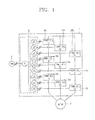
- FIG. 1 is a configuration diagram illustrating an in- series H-bridge medium voltage inverter applied to an embodiment of the present invention in which 3 stages of unit power cells are provided.
- the number of unit power cells is illustrated in an exemplary manner for the sake of convenience, and it should be understood by those skilled in the art that the number of unit power cells can be changed when the need arises.
- a medium voltage inverter 1 applied to the present invention may receive a line-to-line RMS voltage of greater than 600 V, and convert it into a 3-phase voltage and output the converted 3-phase voltage to the electromotor 3.
- the electromotor 3 is a medium voltage 3-phase electromotor, and may include an induction machine or synchronous machine, but may not be necessarily limited to this.
- the medium voltage inverter 1 may include a phase shift transformer 10 and a plurality of unit power cells 20a to 20i.
- the phase shift transformer 10 may provide a galvanic insulation between the input power 2 and the medium voltage inverter 1, and reduce the harmonics of the input terminal, and also provide input 3-phase power suitable to each unit power cell 20a to 20i.
- the unit power cell 20a to 20i receive power from the phase shift transformer 10, and output a phase voltage of the electromotor 3.
- Each unit power cell is composed of three groups.
- the output voltages of the power cells (A1 to A3) 20a, 20b, 20c are connected in series to synthesize the a-phase voltages of the electromotor 3, and power cells (B1 to B3) 20d, 20e, 20f to synthesize the b-phase voltages of the electromotor 3, and power cells (C1 to C3) 20g, 20h, 20i to synthesize the c-phase voltages of the electromotor 3.
- the synthesized b-phase voltages and a-phase voltages have a phase difference of 120 degrees, and the c-phase voltages and b-phase voltages also have a phase difference of 120 degrees.
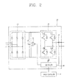
- FIG. 2 is a structural diagram illustrating a unit power cell in FIG. 1 , and each unit power cell has the same structure, and thus is commonly referred to as reference numeral 20 for the description thereof.
- the unit power cell 20 of the high voltage inverter to which the present invention is applied may include a rectifier unit 21, a DC-link capacitor 22, an inverter unit 23, a voltage measurement unit 24, a current measurement unit 25, and a controller 26.
- the controller 26 is connected to the upper controller 4 through a communication line.
- the upper controller 4 is connected to the controller 26 of the each unit power cell 20 to 20i to transmit a control signal.
- the rectifier unit 21 is a 3-phase diode rectifier, for example, and the input thereof is an output of the phase shift transformer 10 in FIG. 1 ,and the output thereof is DC power for which the input 3-phase voltage is rectified.
- the DC-link capacitor 22 stores DC power rectified by the rectifier unit 21.
- the inverter unit 23 is a single phase full bridge inverter in FIG. 2 , for example, and synthesizes the output voltages from the DC-link voltages under the control of the controller 26.
- the inverter unit 23 may not be necessarily limited to the single phase full bridge inverter, and the use of various types of inverters may be not excluded.
- the voltage measurement unit 24 measures a DC-link voltage and the current measurement unit 25 measures an output current of the inverter unit 23.
- the controller 26 controls the switching of each switch 23a to 23d of the inverter unit 23 using the measured voltage and current information.
- the phase shift transformer 10 changes the phase and size of a high voltage to be suitable to the requirement of the unit power cell 20.
- the output voltage of the phase shift transformer 10 becomes an input voltage of the unit power cell 20, and the rectifier unit 21 converts it into a DC voltage.
- the inverter unit 23 of the unit power cell 20 synthesizes AC output voltages from the DC-link voltages. If the DC-link voltage is defined as "E", then the output voltage of the inverter unit 23 may be defined as three levels such as “E", "0" and "-E”. The output voltage is synthesized into “E” if the switches 23a and 23d of the inverter unit in FIG. 2 are conducted, and the output voltage is synthesized into "-E” if the switches 23b and 23c are conducted, and the output voltage is synthesized into "0” if the switches 23a and 23c or 23b and 23d are conducted.
- the series connected output phase voltages may be synthesized into seven levels such as “3E”, “2E”, “E”, “0”, “-E”, “-2E” and “-3E", and furthermore, the output line-to-line voltage of the electromotor 3 may be synthesized into 13 levels such as "6E, "5E”, “4E”, “3E”, “2E”, “E”, “0”, “-E”, “-2E”, “-3E”, “-4E", "-5E” and "-6E” from the synthesized output phase voltages.
- m is a number of levels of the output phase voltage
- H is a number of unit power cells installed for each phase of the electromotor
- p is a number of levels of the output line-to-line voltage.
- the inverter unit 23 of each unit power cell 20 has a single phase full bridge inverter structure, and thus the following voltage ripple exists in the DC-link power.
- the output voltage and output current of each unit power cell 20 are defined as follows.
- Equation 5 it is seen that the output power of the unit power cell 20 is divided into a DC component V 0 I 0 cos ⁇ and a AC component V 0 I 0 cos(2 ⁇ t - ⁇ ), and also it is seen that the AC component has a ripple corresponding to two times of the operating frequency.
- the capacitance reduction of the DC-link capacitor 22 exerts an effect on the ripple of the DC-link voltage.
- the output voltage of the series H-bridge medium voltage inverter 1 is affected according to the size of a DC-link voltage of the unit power cell 20, and in case of FIG. 1 , the output phase voltage of the unit power cell 20 has seven levels such as "3E", “2E”, “E”, “0”, “-E”, “-2E” and “-3E".
- the size of the output phase voltage is instantly changed when the capacitance of the DC-link capacitor 22 is decreased, and thus it is unable to output a stable voltage, and consequently, the capacitance of the DC-link capacitor 22 is required to be estimated in real time.
- the typical failure range of an electrolytic capacitor mainly used for the DC-link capacitor in a medium voltage inverter is a case where there occurs a capacitance change of 15-20%.
- the failure occurs due to thermal, electrical, mechanical, environmental factors, and thermal increase due to an evaporation of electrolytic solution and an increase of ripple current exerts a greater effect on the failure.
- the capacitance of the capacitor is decreased, and the equivalent series resistance (ESR) is increased, and the temperature is increased due to a reduction of ambient temperature, over voltage and effective contact area, thereby accelerating the evaporation of electrolytic solution.
- ESR equivalent series resistance
- a series H-bridge medium voltage inverter in the related art does not estimate a capacitance of the DC-link capacitor 22, and thus it is difficult to determine the fault status.
- the capacitance of the capacitor 22 is decreased to generate a large voltage ripple of the DC-link voltage, and thus a ripple occurs at the output voltage of the medium voltage inverter 1, thereby causing a reduction of the driving performance of the electromotor 3.
- the capacitance of the DC-link capacitor 22 should be periodically measured, but to this end it should be measured in a state that the relevant unit power cell is separated from the entire system, thus causing a problem in that the entire system is periodically suspended or the output thereof should be reduced.
- the capacitance of the DC-link capacitor 22 contained in the unit power cell 20 is estimated in real time to detect the fault status in real time.
- the unit power cell 20 is not required to be separated from the system to estimate the capacitance of the DC-link capacitor 22, thereby facilitating the maintenance.
- a capacitance estimation apparatus is applied to a medium voltage inverter system and a unit power cell thereof as illustrated in FIGS. 1 and 2 , but may not be necessarily limited to this.
- the present invention can be used for an inverter with various voltage ranges in addition to the medium voltage inverter.
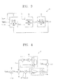
- FIG. 3 is a configuration diagram illustrating a capacitance estimation apparatus of the DC-link capacitor in an inverter according to an embodiment of the present invention, which is applied to the controller 26 of the unit power cell in FIG. 2 .
- an estimation apparatus 30 may include a DC-link voltage estimation unit 31, an evaluation index calculation unit 32, and a DC-link capacitance estimation unit 33.
- the estimation apparatus 30 receives a DC-link voltage (V dc_meas ) measured from the voltage measurement unit 24 and current measurement unit 25 and an output current (i out_ref ) of the inverter unit 23 and an output voltage (V out_ref ) of the inverter unit 23, which is a command voltage of the controller 26, to output an estimated DC-link capacitance (C dc_est ) and an evaluation index (EI).
- V dc_meas DC-link voltage measured from the voltage measurement unit 24 and current measurement unit 25 and an output current (i out_ref ) of the inverter unit 23 and an output voltage (V out_ref ) of the inverter unit 23, which is a command voltage of the controller 26, to output an estimated DC-link capacitance (C dc_est ) and an evaluation index (EI).
- FIG. 4 is a detailed configuration diagram illustrating the DC-link voltage estimation apparatus 31 in FIG. 3 according to an embodiment.
- the DC-link voltage estimation unit 31 may include an output power computation unit 41, a DC-link power estimation unit 42, a DC-link current estimation unit 43, a DC-link voltage estimation unit 44, an error computation unit 45, and a compensation unit 46.
- the output power computation unit 41 computes output power from the output current (i out_ref ) and output voltage (V out_ref ) of the inverter unit 23.
- the DC-link power estimation unit 42 estimates DC-link power from the output power and input power estimated by the compensation unit 46.
- the DC-link power is a value in which the output power is subtracted from the input power.
- the DC-link current estimation unit 43 estimates a current flowing through the DC-link capacitor 22 from the estimated DC-link power.
- the DC-link voltage estimation unit 44 estimates a DC-link voltage using the estimated DC-link current and a DC-link capacitance received from the DC-link capacitance estimation unit 33.
- the error computation unit 45 computes an error between the estimated DC-link voltage and the measured DC-link voltage, and the compensation unit 46 estimates input power from the output of the error computation unit 45.
- the compensation unit 46 may be a proportional integral (PIP) compensator, for example. However, it may not be necessarily limited to this. Furthermore, the PI compensation method has been widely known, and thus the detailed description thereof will be omitted.
- PIP proportional integral
- the evaluation index calculation unit 32 in FIG. 3 calculates an evaluation index from the DC-link voltage estimated by the DC-link voltage estimation unit 44 in FIG. 4 and the measured DC-link voltage.
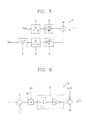
- FIG. 5 is a detailed configuration diagram illustrating the evaluation index calculation unit 32 in FIG. 3 according to an embodiment.
- the evaluation index calculation unit 32 may include a band stop filter (BSF) 51, band pass filters (BPFs) 52, 54, size detection units 53, 55, and a comparison unit 56.
- BPF band stop filter
- BPFs band pass filters
- the band stop filter 51 outputs the measured DC-link voltage by removing a predetermined bandwidth from it, and the band pass filter 52 outputs only a desired bandwidth of the measured DC-link voltage from which the predetermined bandwidth is removed by selecting it.
- the size detection units 53, 55 detect the sizes of the input voltages with a predetermined bandwidth, respectively, and the comparison unit 56 compares the outputs of the size detection units 53, 55 to output an evaluation index. The detailed description thereof will be described later.
- FIG. 6 is a detailed configuration diagram illustrating the DC-link capacitance estimation unit 33 in FIG. 3 according to an embodiment.
- the DC-link capacitance estimation unit 33 may include a comparison unit 61, an operation determination unit 62, an error compensation unit 63, and an addition unit 64.
- the comparison unit 61 compares the evaluation index (EI) which is an output of the comparison unit 56 in FIG. 5 with a reference value.
- the operation determination unit 62 determines the operation of the DC-link capacitance estimation unit 33.
- the error compensation unit 63 compensates an error of the DC-link capacitance estimation, and may be an integral compensator, for example, but it may not be necessarily limited to this. The operation of an integral compensator has been widely known, and thus the detailed description thereof will be omitted.
- the addition unit 64 adds an initial capacitance to the output of the error compensation unit 63 to output an estimated DC-link capacitance.
- FIGS. 3 through 6 will be described.
- Equation 7 The output power of the inverter unit 23 in Equation 5 may be rewritten as in the following Equation 7.
- V o is a size of output voltage
- I o is a size of output current
- ⁇ is a phase angle of the output voltage and output current
- ⁇ is a frequency of the output voltage and output current
- power generated from the inverter unit 23 shows a ripple corresponding to two times of the operating frequency.
- the power of the DC-link capacitor 22 is as follows.
- P in denotes input power to the DC-link
- P out denotes output power from the DC-link to the inverter unit 23.
- Equation 8 can be approximated as follows. P c ⁇ C dc ⁇ V dc ⁇ 0 ⁇ d V dc d t
- FIG. 4 may be illustrated using the above equation.
- the output power computation unit 41 computes Equation 7
- the DC-link power estimation unit 42 computes Equation 8.
- the DC-link current estimation unit 43 and DC-link voltage estimation unit 44 implement Equation 10.
- Input power may be estimated from the error computation unit 45 and compensation unit 46, and the transfer function of an actual DC-link voltage and an estimated DC-link voltage can be obtained as follows.
- V dc_est K p ⁇ s + K l C dc_est ⁇ V dc ⁇ 0 ⁇ s 2 + K p ⁇ s + K l ⁇ V dc - s C dc_est ⁇ V dc ⁇ 0 ⁇ s 2 + K p ⁇ s + K l ⁇ P out
- the compensation unit 46 is a PI compensator, for example, and its gain may be chosen as follows, in a similar manner to a Butterworth filter.
- K p 2 ⁇ ⁇ ⁇ ⁇ n ⁇ C dc_est ⁇ V dc ⁇ 0
- K l C dc_est ⁇ V dc ⁇ 0 ⁇ ⁇ n 2
- the evaluation index calculation unit 32 in FIG. 5 will be described below.
- the evaluation index calculation unit 32 compares a DC-link voltage estimated by the DC-link voltage estimation unit 31 with a size of the actually measured DC-link voltage to calculate an evaluation index, and may be determined such that a capacitance change of the DC-link capacitor 22 is smaller as the evaluation index is closer to 1.
- signal processing is required to be carried out by the band stop filter 51, band pass filters 52, 54, and size detection units 53, 55. It may be carried out on the assumption that the output of the inverter unit 23 can be calculated in a more accurate manner when using the command voltage and measured current in FIG. 2 .
- the band stop filter 51 removes a component corresponding to the sixth harmonic of the input frequency.
- a system using the rectifier unit 21 with a three-phase diode as illustrated in FIG. 2 generates ripple power corresponding to the sixth harmonic of the input power frequency all the time, but according to the present invention only the second harmonic of the output power frequency is taken into consideration, and thus filtering thereof is required.
- the band pass filter 52 filters out a component corresponding to the second harmonic of the output power frequency shown at the measured DC-link voltage.
- the band pass filter 54 filters out a component corresponding to the second harmonic of the output power frequency shown at the estimated DC-link voltage.
- the size detection units 53, 55 obtains the size of a ripple voltage.
- the size thereof is detected through the size detection units 53, 55 without directly using the output of the band pass filters 52, 54 is because an error due to the phase difference occurs when directly comparing it with a ripple voltage due to the ripple power.
- the comparison unit 56 divides the size of the estimated ripple power by the size of the measured ripple power to determine an evaluation index.
- the range of the evaluation index may be selected in a suitable manner to determine the fault status of the DC-link capacitor 22 of the unit power cell 20.
- the DC-link capacitance estimation unit 33 estimates the capacitance of the DC-link capacitor 22 using the evaluation index.
- the DC-link capacitance estimation unit 33 calculates the capacitance of the DC-link capacitor 22 using such a property.
- the initial DC-link capacitance may be an initially measured value or an initially designed nominal value.
- the DC-link voltage is estimated, and compared with the ripple size of the measured DC-link voltage to estimate the DC-link capacitance.
- the capacitance of the DC-link capacitor 22 contained in the unit power cell 20 is estimated in real time to detect the fault status in real time. Furthermore, the unit power cell 20 is not required to be separated from the system to estimate the capacitance of the DC-link capacitor 22, thereby facilitating the maintenance.
- the foregoing present invention has an effect capable of estimating the capacitance of the DC-link capacitor contained in the inverter to simply detect the fault status in real time.
Landscapes
- Physics & Mathematics (AREA)
- General Physics & Mathematics (AREA)
- Engineering & Computer Science (AREA)
- Power Engineering (AREA)
- Inverter Devices (AREA)
- Testing Electric Properties And Detecting Electric Faults (AREA)
Applications Claiming Priority (1)
| Application Number | Priority Date | Filing Date | Title |
|---|---|---|---|
| KR1020120081992A KR101667833B1 (ko) | 2012-07-26 | 2012-07-26 | 인버터에서 직류단 커패시터의 용량 추정장치 |
Publications (2)
| Publication Number | Publication Date |
|---|---|
| EP2690452A2 true EP2690452A2 (de) | 2014-01-29 |
| EP2690452A3 EP2690452A3 (de) | 2017-11-01 |
Family
ID=48746365
Family Applications (1)
| Application Number | Title | Priority Date | Filing Date |
|---|---|---|---|
| EP13175536.5A Withdrawn EP2690452A3 (de) | 2012-07-26 | 2013-07-08 | Vorrichtung zur Schätzung der Kapazität eines Gleichstromzwischenkreiskondensators in einem Wechselrichter |
Country Status (5)
| Country | Link |
|---|---|
| US (1) | US9557360B2 (de) |
| EP (1) | EP2690452A3 (de) |
| JP (1) | JP5612738B2 (de) |
| KR (1) | KR101667833B1 (de) |
| CN (1) | CN103580497B (de) |
Cited By (2)
| Publication number | Priority date | Publication date | Assignee | Title |
|---|---|---|---|---|
| WO2015071378A1 (de) | 2013-11-14 | 2015-05-21 | Sma Solar Technology Ag | Verfahren und wechselrichter zum bestimmen von kapazitätswerten von kapazitäten einer energieversorgungsanlage |
| US10569800B2 (en) | 2017-06-29 | 2020-02-25 | Trw Limited | Monitoring system for electric power assisted steering |
Families Citing this family (23)
| Publication number | Priority date | Publication date | Assignee | Title |
|---|---|---|---|---|
| JP6424078B2 (ja) | 2014-02-13 | 2018-11-14 | 山洋電気株式会社 | ステータ、ステータの製造方法、およびモータ |
| DE102014202717B3 (de) | 2014-02-14 | 2015-06-11 | Robert Bosch Gmbh | System zur Kapazitätsbestimmung eines Zwischenkreiskondensators und Verfahren zum Ansteuern eines Wechselrichters |
| KR101605990B1 (ko) | 2015-03-25 | 2016-03-23 | 영남대학교 산학협력단 | 인버터 벡터 구동 시스템 및 그것을 이용한 커패시터 용량 추정 방법 |
| CN105577011B (zh) * | 2016-01-18 | 2018-02-02 | 电子科技大学 | 一种三电平逆变器的直流电容容量获取方法 |
| EP3223023B1 (de) * | 2016-03-24 | 2019-12-04 | ABB Schweiz AG | Verfahren und vorrichtung zur schätzung der kapazität eines gleichspannungszwischenkreises |
| KR20180007874A (ko) * | 2016-07-14 | 2018-01-24 | 삼성전기주식회사 | 코일 부품 및 이의 제조 방법 |
| CN108169571B (zh) | 2016-12-07 | 2020-06-02 | 台达电子企业管理(上海)有限公司 | 监测直流母线电容容值的方法和装置 |
| JP6438453B2 (ja) | 2016-12-21 | 2018-12-12 | ファナック株式会社 | モータ駆動装置 |
| CN109387701B (zh) * | 2017-08-02 | 2021-03-19 | 台达电子工业股份有限公司 | 三相变流装置及电容估算方法 |
| WO2019127185A1 (en) * | 2017-12-28 | 2019-07-04 | Abb Schweiz Ag | Method and system for on-line condition monitoring of dc-link capacitor in power converter |
| JP6369737B1 (ja) * | 2018-04-06 | 2018-08-08 | 富士電機株式会社 | 絶縁型dc/dcコンバータ及びその制御装置、並びにdc/ac変換装置 |
| CN110556789B (zh) * | 2018-05-31 | 2021-11-19 | 株洲中车时代电气股份有限公司 | 一种车载逆变器输出滤波电容的故障保护方法及系统 |
| CN112219349B (zh) | 2018-06-13 | 2024-09-10 | 三菱电机株式会社 | 电容器电容估计装置、汽车控制系统、fa系统和电容器电容估计方法 |
| CN109061314B (zh) | 2018-06-29 | 2021-05-11 | 华为技术有限公司 | 一种检测逆变器的滤波电容容值的方法及装置 |
| US11876438B2 (en) * | 2019-01-04 | 2024-01-16 | Innomotics Gmbh | Reducing input harmonic distortion in a power supply |
| CN111505524B (zh) * | 2019-01-30 | 2022-09-23 | 台达电子工业股份有限公司 | 级联变换器的在线监测方法及所适用的级联变换器 |
| DE102019117369A1 (de) * | 2019-06-27 | 2020-12-31 | Ebm-Papst Mulfingen Gmbh & Co. Kg | Schaltung und Verfahren zur Überwachung eines Zwischenkreiskondensators |
| WO2021009831A1 (ja) * | 2019-07-16 | 2021-01-21 | 株式会社日立産機システム | 電力変換装置および劣化診断システム |
| CN112904073B (zh) * | 2021-01-21 | 2022-01-14 | 哈尔滨工业大学 | 无电解电容永磁压缩机驱动系统母线电容容值估计方法 |
| CN114839470B (zh) * | 2022-07-06 | 2022-10-11 | 西安交通大学 | Mmc系统子模块的电容器监测方法、装置、设备和介质 |
| GB202212285D0 (en) | 2022-08-24 | 2022-10-05 | Rolls Royce Plc | Circuitry and methods for monitoring power conversion circuitry |
| KR102848489B1 (ko) * | 2023-12-04 | 2025-08-22 | 한국철도기술연구원 | 멀티레벨 전력변환장치의 스위치 고장진단 시스템 및 방법 |
| WO2026013876A1 (ja) * | 2024-07-12 | 2026-01-15 | 三菱電機株式会社 | 電力変換装置 |
Family Cites Families (12)
| Publication number | Priority date | Publication date | Assignee | Title |
|---|---|---|---|---|
| JPH05308701A (ja) | 1992-04-30 | 1993-11-19 | Mitsubishi Electric Corp | 交流電気車の制御装置 |
| JPH1014097A (ja) | 1996-06-18 | 1998-01-16 | Hitachi Ltd | 電力変換器のコンデンサ容量判定装置 |
| KR100330662B1 (ko) * | 1999-12-27 | 2002-03-29 | 정명식 | 고성능 펄스 폭 변조 컨버터-인버터 시스템 |
| CN2733369Y (zh) * | 2004-10-10 | 2005-10-12 | 广州智光电力电子有限公司 | 一种电压源型高压逆变系统整流滤波电容实时检测器 |
| JP2008172910A (ja) | 2007-01-11 | 2008-07-24 | Yaskawa Electric Corp | 電力変換装置 |
| US7830269B2 (en) | 2007-09-14 | 2010-11-09 | Astec International Limited | Health monitoring for power converter capacitors |
| WO2010055556A1 (ja) | 2008-11-12 | 2010-05-20 | 三菱電機株式会社 | 電力変換装置のコンデンサ容量推定装置およびコンデンサ容量推定方法 |
| JP2010259165A (ja) | 2009-04-22 | 2010-11-11 | Kyocera Corp | 電力供給装置、電子装置、及び、コンデンサ容量推定方法 |
| KR101019342B1 (ko) * | 2009-05-04 | 2011-03-07 | 손진근 | 전력변환장치에서의 직류 출력 필터 커패시터의 온라인 고장검출 시스템 |
| KR101090509B1 (ko) * | 2009-08-05 | 2011-12-07 | 울산대학교 산학협력단 | 인버터 및 인버터의 제어 방법 |
| KR101175415B1 (ko) * | 2009-11-16 | 2012-08-20 | 영남대학교 산학협력단 | 단상 pwm 컨버터의 직류 링크 커패시터 용량 추정 시스템 |
| JP5045772B2 (ja) | 2010-03-11 | 2012-10-10 | オムロン株式会社 | パワーコンディショナ内のコンデンサ容量抜け検出方法、それを実施するパワーコンディショナおよびそれを備えた太陽光発電システム |
-
2012
- 2012-07-26 KR KR1020120081992A patent/KR101667833B1/ko not_active Expired - Fee Related
-
2013
- 2013-07-08 EP EP13175536.5A patent/EP2690452A3/de not_active Withdrawn
- 2013-07-08 US US13/937,037 patent/US9557360B2/en not_active Expired - Fee Related
- 2013-07-24 JP JP2013153425A patent/JP5612738B2/ja not_active Expired - Fee Related
- 2013-07-26 CN CN201310321022.3A patent/CN103580497B/zh not_active Expired - Fee Related
Non-Patent Citations (1)
| Title |
|---|
| None |
Cited By (5)
| Publication number | Priority date | Publication date | Assignee | Title |
|---|---|---|---|---|
| WO2015071378A1 (de) | 2013-11-14 | 2015-05-21 | Sma Solar Technology Ag | Verfahren und wechselrichter zum bestimmen von kapazitätswerten von kapazitäten einer energieversorgungsanlage |
| DE102013112538A1 (de) | 2013-11-14 | 2015-05-21 | Sma Solar Technology Ag | Verfahren und Wechselrichter zum Bestimmen von Kapazitätswerten von Kapazitäten einer Energieversorgungsanlage |
| DE102013112538B4 (de) | 2013-11-14 | 2018-04-05 | Sma Solar Technology Ag | Verfahren und Wechselrichter zum Bestimmen von Kapazitätswerten von Kapazitäten einer Energieversorgungsanlage |
| US10569800B2 (en) | 2017-06-29 | 2020-02-25 | Trw Limited | Monitoring system for electric power assisted steering |
| EP3421327B1 (de) * | 2017-06-29 | 2021-04-07 | ZF Automotive UK Limited | Überwachungssystem für elektrische servolenkung |
Also Published As
| Publication number | Publication date |
|---|---|
| KR20140013730A (ko) | 2014-02-05 |
| CN103580497B (zh) | 2015-11-25 |
| US20140032145A1 (en) | 2014-01-30 |
| KR101667833B1 (ko) | 2016-10-19 |
| EP2690452A3 (de) | 2017-11-01 |
| JP2014025927A (ja) | 2014-02-06 |
| US9557360B2 (en) | 2017-01-31 |
| JP5612738B2 (ja) | 2014-10-22 |
| CN103580497A (zh) | 2014-02-12 |
Similar Documents
| Publication | Publication Date | Title |
|---|---|---|
| US9557360B2 (en) | Apparatus for estimating capacitance of DC-link capacitor in inverter | |
| EP2937983B1 (de) | Filterkondensatorabbauidentifizierung durch verwendung von berechnetem strom | |
| US9294005B2 (en) | Method and apparatus for detecting AFE filter capacitor degradation | |
| EP2725366B1 (de) | Vorrichtung zur Schätzung der Kapazität eines Gleichstromzwischenkreiskondensators in einem Wechselrichter | |
| EP2814150B1 (de) | Verfahren und Vorrichtung für aktive Frontfilterkondensatorverschlechterungserkennung | |
| EP2482411B1 (de) | Laufwerkfehlerschutz | |
| EP3220523B1 (de) | Phasenausfallerkennung in aktiven einspeiseumrichtern | |
| EP2953246A2 (de) | Filterkondensatorabbauidentifizierung mittels gemessener und erwarteter spannung | |
| EP2660962A2 (de) | Verfahren und Vorrichtung zur Detektion der Beeinträchtigung der Wirksamkeit von Filterkondensatoren | |
| EP3116117B1 (de) | Wechselrichterprüfvorrichtung | |
| CN108093672B (zh) | 逆变器基板、连接顺序的判断方法、缺相判断方法 | |
| EP2680425A1 (de) | Stromwandler | |
| US10784677B2 (en) | Enhanced utility disturbance monitor | |
| US10014792B2 (en) | Multi-phase electric drive and power unit thereof for use with a multi-phase AC load | |
| EP3016274B1 (de) | Vorrichtung zur steuerung eines umrichters | |
| US20210203251A1 (en) | Electrically coupling a first electrical supply network to a second electrical supply network | |
| JP4857486B2 (ja) | 系統連系インバータ | |
| US12166409B2 (en) | Power conversion device and control device | |
| KR101904101B1 (ko) | Mmc 컨버터 출력단 직류성분 제거방법 | |
| CN108957217B (zh) | 交直交供电系统控制与保护方法 | |
| US12140613B2 (en) | Open-phase detection circuit and power conversion apparatus | |
| JP2016103902A (ja) | 電力変換装置およびその制御方法 | |
| JP2022022061A (ja) | 計測装置、計測方法及び電力変換装置 |
Legal Events
| Date | Code | Title | Description |
|---|---|---|---|
| PUAI | Public reference made under article 153(3) epc to a published international application that has entered the european phase |
Free format text: ORIGINAL CODE: 0009012 |
|
| AK | Designated contracting states |
Kind code of ref document: A2 Designated state(s): AL AT BE BG CH CY CZ DE DK EE ES FI FR GB GR HR HU IE IS IT LI LT LU LV MC MK MT NL NO PL PT RO RS SE SI SK SM TR |
|
| AX | Request for extension of the european patent |
Extension state: BA ME |
|
| PUAL | Search report despatched |
Free format text: ORIGINAL CODE: 0009013 |
|
| AK | Designated contracting states |
Kind code of ref document: A3 Designated state(s): AL AT BE BG CH CY CZ DE DK EE ES FI FR GB GR HR HU IE IS IT LI LT LU LV MC MK MT NL NO PL PT RO RS SE SI SK SM TR |
|
| AX | Request for extension of the european patent |
Extension state: BA ME |
|
| RIC1 | Information provided on ipc code assigned before grant |
Ipc: H02M 1/00 20070101ALI20170926BHEP Ipc: G01R 31/42 20060101ALN20170926BHEP Ipc: G01R 27/26 20060101AFI20170926BHEP Ipc: H02M 7/49 20070101ALI20170926BHEP |
|
| 17P | Request for examination filed |
Effective date: 20180502 |
|
| RBV | Designated contracting states (corrected) |
Designated state(s): AL AT BE BG CH CY CZ DE DK EE ES FI FR GB GR HR HU IE IS IT LI LT LU LV MC MK MT NL NO PL PT RO RS SE SI SK SM TR |
|
| STAA | Information on the status of an ep patent application or granted ep patent |
Free format text: STATUS: THE APPLICATION HAS BEEN WITHDRAWN |
|
| 18W | Application withdrawn |
Effective date: 20201113 |