EP2690518A2 - Differenzdruckregler mit variablem Widerstand - Google Patents
Differenzdruckregler mit variablem Widerstand Download PDFInfo
- Publication number
- EP2690518A2 EP2690518A2 EP20130169477 EP13169477A EP2690518A2 EP 2690518 A2 EP2690518 A2 EP 2690518A2 EP 20130169477 EP20130169477 EP 20130169477 EP 13169477 A EP13169477 A EP 13169477A EP 2690518 A2 EP2690518 A2 EP 2690518A2
- Authority
- EP
- European Patent Office
- Prior art keywords
- variable resistance
- differential pressure
- housing
- pressure regulator
- resistance differential
- Prior art date
- Legal status (The legal status is an assumption and is not a legal conclusion. Google has not performed a legal analysis and makes no representation as to the accuracy of the status listed.)
- Withdrawn
Links
- 230000006835 compression Effects 0.000 claims abstract description 9
- 238000007906 compression Methods 0.000 claims abstract description 9
- 239000012530 fluid Substances 0.000 claims description 21
- 238000011144 upstream manufacturing Methods 0.000 claims description 5
- 230000000717 retained effect Effects 0.000 claims description 4
- 239000002184 metal Substances 0.000 claims description 3
- 230000001105 regulatory effect Effects 0.000 abstract 1
- 230000009467 reduction Effects 0.000 description 9
- 230000008901 benefit Effects 0.000 description 4
- 230000001066 destructive effect Effects 0.000 description 3
- 239000007788 liquid Substances 0.000 description 3
- 238000000034 method Methods 0.000 description 3
- 238000007599 discharging Methods 0.000 description 2
- 230000004048 modification Effects 0.000 description 2
- 238000012986 modification Methods 0.000 description 2
- XLYOFNOQVPJJNP-UHFFFAOYSA-N water Substances O XLYOFNOQVPJJNP-UHFFFAOYSA-N 0.000 description 2
- 239000006227 byproduct Substances 0.000 description 1
- 230000007423 decrease Effects 0.000 description 1
- 230000003247 decreasing effect Effects 0.000 description 1
- 230000001419 dependent effect Effects 0.000 description 1
- 229920001971 elastomer Polymers 0.000 description 1
- 239000000806 elastomer Substances 0.000 description 1
- 239000007789 gas Substances 0.000 description 1
- 230000008569 process Effects 0.000 description 1
- 229910001220 stainless steel Inorganic materials 0.000 description 1
- 239000010935 stainless steel Substances 0.000 description 1
Images
Classifications
-
- F—MECHANICAL ENGINEERING; LIGHTING; HEATING; WEAPONS; BLASTING
- F16—ENGINEERING ELEMENTS AND UNITS; GENERAL MEASURES FOR PRODUCING AND MAINTAINING EFFECTIVE FUNCTIONING OF MACHINES OR INSTALLATIONS; THERMAL INSULATION IN GENERAL
- F16K—VALVES; TAPS; COCKS; ACTUATING-FLOATS; DEVICES FOR VENTING OR AERATING
- F16K17/00—Safety valves; Equalising valves, e.g. pressure relief valves
- F16K17/18—Safety valves; Equalising valves, e.g. pressure relief valves opening on surplus pressure on either side
- F16K17/19—Equalising valves predominantly for tanks
-
- F—MECHANICAL ENGINEERING; LIGHTING; HEATING; WEAPONS; BLASTING
- F16—ENGINEERING ELEMENTS AND UNITS; GENERAL MEASURES FOR PRODUCING AND MAINTAINING EFFECTIVE FUNCTIONING OF MACHINES OR INSTALLATIONS; THERMAL INSULATION IN GENERAL
- F16K—VALVES; TAPS; COCKS; ACTUATING-FLOATS; DEVICES FOR VENTING OR AERATING
- F16K47/00—Means in valves for absorbing fluid energy
- F16K47/08—Means in valves for absorbing fluid energy for decreasing pressure or noise level and having a throttling member separate from the closure member, e.g. screens, slots, labyrinths
-
- F—MECHANICAL ENGINEERING; LIGHTING; HEATING; WEAPONS; BLASTING
- F16—ENGINEERING ELEMENTS AND UNITS; GENERAL MEASURES FOR PRODUCING AND MAINTAINING EFFECTIVE FUNCTIONING OF MACHINES OR INSTALLATIONS; THERMAL INSULATION IN GENERAL
- F16K—VALVES; TAPS; COCKS; ACTUATING-FLOATS; DEVICES FOR VENTING OR AERATING
- F16K1/00—Lift valves or globe valves, i.e. cut-off apparatus with closure members having at least a component of their opening and closing motion perpendicular to the closing faces
- F16K1/16—Lift valves or globe valves, i.e. cut-off apparatus with closure members having at least a component of their opening and closing motion perpendicular to the closing faces with pivoted closure-members
- F16K1/18—Lift valves or globe valves, i.e. cut-off apparatus with closure members having at least a component of their opening and closing motion perpendicular to the closing faces with pivoted closure-members with pivoted discs or flaps
- F16K1/22—Lift valves or globe valves, i.e. cut-off apparatus with closure members having at least a component of their opening and closing motion perpendicular to the closing faces with pivoted closure-members with pivoted discs or flaps with axis of rotation crossing the valve member, e.g. butterfly valves
-
- F—MECHANICAL ENGINEERING; LIGHTING; HEATING; WEAPONS; BLASTING
- F16—ENGINEERING ELEMENTS AND UNITS; GENERAL MEASURES FOR PRODUCING AND MAINTAINING EFFECTIVE FUNCTIONING OF MACHINES OR INSTALLATIONS; THERMAL INSULATION IN GENERAL
- F16K—VALVES; TAPS; COCKS; ACTUATING-FLOATS; DEVICES FOR VENTING OR AERATING
- F16K1/00—Lift valves or globe valves, i.e. cut-off apparatus with closure members having at least a component of their opening and closing motion perpendicular to the closing faces
- F16K1/32—Details
- F16K1/52—Means for additional adjustment of the rate of flow
- F16K1/526—Means for additional adjustment of the rate of flow for limiting the maximum flow rate, using a second valve
-
- G—PHYSICS
- G05—CONTROLLING; REGULATING
- G05D—SYSTEMS FOR CONTROLLING OR REGULATING NON-ELECTRIC VARIABLES
- G05D16/00—Control of fluid pressure
- G05D16/028—Controlling a pressure difference
-
- G—PHYSICS
- G05—CONTROLLING; REGULATING
- G05D—SYSTEMS FOR CONTROLLING OR REGULATING NON-ELECTRIC VARIABLES
- G05D16/00—Control of fluid pressure
- G05D16/04—Control of fluid pressure without auxiliary power
- G05D16/06—Control of fluid pressure without auxiliary power the sensing element being a flexible membrane, yielding to pressure, e.g. diaphragm, bellows, capsule
- G05D16/063—Control of fluid pressure without auxiliary power the sensing element being a flexible membrane, yielding to pressure, e.g. diaphragm, bellows, capsule the sensing element being a membrane
- G05D16/0644—Control of fluid pressure without auxiliary power the sensing element being a flexible membrane, yielding to pressure, e.g. diaphragm, bellows, capsule the sensing element being a membrane the membrane acting directly on the obturator
- G05D16/0655—Control of fluid pressure without auxiliary power the sensing element being a flexible membrane, yielding to pressure, e.g. diaphragm, bellows, capsule the sensing element being a membrane the membrane acting directly on the obturator using one spring-loaded membrane
- G05D16/0658—Control of fluid pressure without auxiliary power the sensing element being a flexible membrane, yielding to pressure, e.g. diaphragm, bellows, capsule the sensing element being a membrane the membrane acting directly on the obturator using one spring-loaded membrane characterised by the form of the obturator
-
- Y—GENERAL TAGGING OF NEW TECHNOLOGICAL DEVELOPMENTS; GENERAL TAGGING OF CROSS-SECTIONAL TECHNOLOGIES SPANNING OVER SEVERAL SECTIONS OF THE IPC; TECHNICAL SUBJECTS COVERED BY FORMER USPC CROSS-REFERENCE ART COLLECTIONS [XRACs] AND DIGESTS
- Y10—TECHNICAL SUBJECTS COVERED BY FORMER USPC
- Y10T—TECHNICAL SUBJECTS COVERED BY FORMER US CLASSIFICATION
- Y10T137/00—Fluid handling
- Y10T137/7722—Line condition change responsive valves
- Y10T137/7781—With separate connected fluid reactor surface
- Y10T137/7793—With opening bias [e.g., pressure regulator]
Definitions
- the invented device is intended for automatic control applications, and more specifically, for the reduction of high fluid pressures associated with the control of such process variables as volume, temperature, level and pressure of liquid or gaseous fluids.
- valve housings featuring multiport cages, for example. While moderately effective, they are costly and require larger valve sizes due to the restrictive capacity of such cages. Furthermore, such openings have constant size flow openings that are unable to adapt to different flow conditions.
- the present invention overcomes these and other limitations of current devices by providing a two-stage pressure reduction system, where the ratio between the inlet pressure and outlet pressure across each stage remains nearly constant regardless of variations in flow.
- fluid conducting perforations in the invention's secondary device adapt to the typical increase in differential pressure with decreasing flow rate, thereby offering enhanced noise reduction, where it is needed.
- Another great advantage of the invented system is, that it can be adapted to any conventional flow control valve, without need to have special low noise inserts, since these devices are used only to regulate the flowing quantity when the assigned pressure drop across such valves is only fifteen to twenty percent of the total differential pressure across the system, as such staying well out of the range where noisy or destructive conditions are encountered.
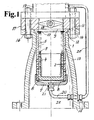
- Fig. 1 shows a central, cross-sectional view of the invention in combination with a conventional butterfly valve, where both, the valve and the fluid conducting perforations are in the closed positions.
- the invention comprises a cylindrical housing 1, having a perforated portion 2.
- Housing 1 has a first opening 3 admitting a perforated piston 4 in the cylindrical bore 5, closed at a second opening 6 by a flange 7.
- the latter retains a pressurized diaphragm 8, capable of motivating said piston against a compression spring 9, which is shouldered against a retainer 10.
- Diaphragm 8 is preferably made from a flexible metal such as stainless steel, otherwise an elastomer can be used.
- Housing 1 has an enlarged rim 11 fitting into a complimentary recess 12 which retains the housing within a piping component 13, comprising of a flanged smaller bore 14 and a larger flanged downstream bore 15, whereby the smaller flanged portion is attached by means of fasteners 16, to a conventional control valve 17.
- Valve 17 is here featured as a butterfly valve, having an outlet 18. It should be understood that the invention is not limited to the choice of a specific valve type. For example, globe style valves or ball valves may be employed just as well instead of the shown butterfly valve.
- Control valve 17 is additionally connected to an inlet pipe 19, capable of admitting high pressure to the inlet of said control valve.
- a tube 20 is suitably connected to said inlet pipe 19 to conduct high pressure fluid to the interior of the flange 7 by means of port 21.
- piston 4 is pushed against spring 9 by the up-stream pressure acting on diaphragm 6, causing the piston to slide past the equally spaced perforations in housing 1 and thereby preventing fluid from escaping the housing and into the piping system interior 22.
- valve 17 Conversely, once the valve 17 has opened and admitted fluid to the interior of housing 1, pressure will build up till sufficient pressure plus the load exerted by spring 9 will cause the piston to slide in the direction of flange 7 and thereby cause a portion of the perforations to be overlapping and as a result start discharging fluid.
- the amount of overlap is self-regulating and the amount of overlap is directly proportional to the amount of fluid discharging from the control valve.
- the difference between the reduction of the upstream pressure ahead of the control valve 17 and the pressure motivating the piston to open the perforations is typically chosen to be equivalent to be between ten and thirty percent of the upstream pressure. This ratio is determined by the chosen force and spring rate of the compression spring 9. This means, that between seventy and ninety percent of the upstream pressure energy is converted by the perforations, which are well suited for the task.
- the preferred configuration of the perforations are drilled holes, however, a number of equally spaced cylindrical slots would serve just as well.
- the diameter of the holes is determined by aerodynamic noise consideration.
- Each hole should produce a peak noise frequency in the downstream pipe that is at least twice that of the ring frequency of the pipe. The result is a better sound attenuation, in this case about 13.5 Decibel sound reduction compared to a conventional valve having a peak frequency of 0.25 of the pipe's ring frequency, see reference 1.
- a preferred hole diameter typically is between two and six percent of the downstream pipe diameter.
- the larger outlet diameter 15 of the piping system 13 is dimensioned to be at least ten percent larger than the flanged inlet opening 14. The purpose is, to prevent high velocity jets exiting from the perforations in the housing 1 to impinge on the interior wall of the piping interior 22 and cause damage.
- the size of the perforations in the piston slightly larger than those it the housing.
- the purpose is to compensate for possible misalignment between the two sets of openings and to make sure, that the point of maximum velocity of the fluid occurs in the final openings which are located in the housing.
- a typical choice would be, that the diameter of the perforation in the piston should be eight percent or more larger than those in the housing.
- Embodiment 1 Variable resistance differential pressure regulator comprising a housing, located inside a piping component, having a cylindrical bore slidingly engaging a perforated piston motivated by one or more compression springs at a first opening and counteracted by a pressurized diaphragm suitably retained at a second opening, and wherein said housing having a perforated portion whereby both sets of perforations are completely overlapping when the piston is in one fixed travel position in order to convey fluid entering from the interior of said piston to the exterior of the housing, said piping component having a smaller bore capable to connect to the outlet of a control valve and having an opposed larger bore capable of connecting to an downstream pipe.
- Embodiment 2 Variable resistance differential pressure regulator as in embodiment 1, wherein said diaphragm is fastened and sealed at the other opening of said housing by a flange.
- Embodiment 3 Variable resistance differential pressure regulator as in embodiment 2, wherein said flange has a port to convey fluid pressure from the upstream side of a control valve to said diaphragm.
- Embodiment 4 Variable resistance differential pressure regulator as in embodiment 1, wherein said piston, when motivated by said diaphragm, is capable of sliding to a position where there is no more overlapping of said perforations and thereby stopping the flow of fluid from the interior of the piston to exterior of said housing.
- Embodiment 5 Variable resistance differential pressure regulator as in embodiment 1, wherein said diaphragm is composed of flexible metal.
- Embodiment 6 Variable resistance differential pressure regulator as in embodiment 1, wherein said compression springs are suitably retained within the first opening of said housing.
- Embodiment 7 Variable resistance differential pressure regulator as in embodiment 6, wherein the compression force of said spring or springs is able to exert a force of between ten to thirty percent of the force produced by fluid pressure imposed on the diaphragm.
- Embodiment 8 Variable resistance differential pressure regulator as in embodiment 1, wherein said housing has an enlarged rim near the first opening intersecting with a similar opening at the inlet side of said piping component in order to retain the housing.
- Embodiment 9 Variable resistance differential pressure regulator as in embodiment 1, wherein the larger bore of the piping component has a diameter that is at least ten percent larger than the smaller bore.
- Embodiment 10 Variable resistance differential pressure regulator as in embodiment 1, wherein the perforations within the housing have a diameter being between two and five percent of the diameter of the larger bore in the piping system.
- Embodiment 11 Variable resistance differential pressure regulator as in embodiment 1, wherein the diameter of the perforations in the piston are more than eight percent larger than the diameter of the perforations in the housing.
- Embodiment 12 Variable resistance differential pressure regulator as in embodiment 1, wherein the perforations are in form of radial slots.
Landscapes
- Engineering & Computer Science (AREA)
- General Engineering & Computer Science (AREA)
- Physics & Mathematics (AREA)
- Mechanical Engineering (AREA)
- Fluid Mechanics (AREA)
- General Physics & Mathematics (AREA)
- Automation & Control Theory (AREA)
- Control Of Fluid Pressure (AREA)
- Details Of Valves (AREA)
Applications Claiming Priority (1)
| Application Number | Priority Date | Filing Date | Title |
|---|---|---|---|
| US13/507,711 US20140020771A1 (en) | 2012-07-23 | 2012-07-23 | Variable resistance differential pressure regulator |
Publications (1)
| Publication Number | Publication Date |
|---|---|
| EP2690518A2 true EP2690518A2 (de) | 2014-01-29 |
Family
ID=48536713
Family Applications (1)
| Application Number | Title | Priority Date | Filing Date |
|---|---|---|---|
| EP20130169477 Withdrawn EP2690518A2 (de) | 2012-07-23 | 2013-05-28 | Differenzdruckregler mit variablem Widerstand |
Country Status (2)
| Country | Link |
|---|---|
| US (1) | US20140020771A1 (de) |
| EP (1) | EP2690518A2 (de) |
Cited By (1)
| Publication number | Priority date | Publication date | Assignee | Title |
|---|---|---|---|---|
| CN108150656A (zh) * | 2018-02-12 | 2018-06-12 | 无锡智能自控工程股份有限公司 | 先导型串式调节切断阀 |
Families Citing this family (4)
| Publication number | Priority date | Publication date | Assignee | Title |
|---|---|---|---|---|
| JP2016173048A (ja) * | 2015-03-17 | 2016-09-29 | アイシン精機株式会社 | 圧力レギュレータ |
| FR3048750B1 (fr) * | 2016-03-14 | 2018-07-27 | Suntec Industries France | Dispositif regulateur de pression d'une vanne gaz |
| CN108036107B (zh) * | 2017-11-01 | 2019-09-27 | 宁乡宣文环保机械有限公司 | 一种释放器 |
| CN113324096B (zh) * | 2021-05-18 | 2023-01-03 | 哈尔滨工程大学 | 一种具有两级弹簧及气腔的防水锤阀 |
Family Cites Families (21)
| Publication number | Priority date | Publication date | Assignee | Title |
|---|---|---|---|---|
| US1673041A (en) * | 1926-10-29 | 1928-06-12 | Builders Iron Foundry | Rate of flow controller |
| US1904204A (en) * | 1927-12-05 | 1933-04-18 | Mrs Edna Fuselier Delery | Fluid control valve |
| US2192042A (en) * | 1936-09-25 | 1940-02-27 | Gen Electric | Fluid control mechanism |
| US2807144A (en) * | 1953-09-21 | 1957-09-24 | Weatherhead Co | Flow regulator for liquefied gases |
| US3115892A (en) * | 1954-10-11 | 1963-12-31 | Fischer & Porter Co | Flow controller |
| US2942619A (en) * | 1957-01-25 | 1960-06-28 | Tecalemit Ltd | Flow control valves |
| US3095176A (en) * | 1959-01-29 | 1963-06-25 | Int Basic Economy Corp | Fluid control valves |
| US3064676A (en) * | 1959-09-01 | 1962-11-20 | Stephen C Baker | Hydraulic flow control valve |
| US3324879A (en) * | 1965-10-22 | 1967-06-13 | Frederick Robertson | Faucet valve with stationary inlet tube |
| US3602252A (en) * | 1969-08-18 | 1971-08-31 | Eaton Yale & Towne | Constant flow heater valve |
| US3729018A (en) * | 1971-07-06 | 1973-04-24 | Spraying Systems Co | Unloader valve for spray guns |
| US3783892A (en) * | 1972-10-03 | 1974-01-08 | Honeywell Inc | Long timing, slow flow device |
| FR2339203A1 (fr) * | 1976-01-20 | 1977-08-19 | Bronzavia Sa | Dispositif de reglage de la pression differentielle entre deux points de pressions differentes d'un circuit de fluide |
| IT1113795B (it) * | 1977-12-01 | 1986-01-20 | Pirelli | Valvola regolatrice di flusso perfezionata |
| JPS58133229A (ja) * | 1982-02-02 | 1983-08-08 | オリンパス光学工業株式会社 | 内視鏡の吸引切換え弁 |
| US4783043A (en) * | 1987-05-04 | 1988-11-08 | Sundstrand Corporation | Hydraulic snub valve |
| US5143116A (en) * | 1989-12-11 | 1992-09-01 | Skoglund Paul K | Flow regulating valve and system using the same |
| US5971012A (en) * | 1993-06-01 | 1999-10-26 | Skoglund; Paul K. | Constant flow control valve having matable piston sleeve and outlet cover |
| US6817416B2 (en) * | 2000-08-17 | 2004-11-16 | Abb Offshore Systems Limited | Flow control device |
| US6932107B2 (en) * | 2003-06-24 | 2005-08-23 | Flow Control Industries, Inc. | Flow control valves |
| US7647942B2 (en) * | 2007-02-21 | 2010-01-19 | Victaulic Company | Constant flow rate valve |
-
2012
- 2012-07-23 US US13/507,711 patent/US20140020771A1/en not_active Abandoned
-
2013
- 2013-05-28 EP EP20130169477 patent/EP2690518A2/de not_active Withdrawn
Non-Patent Citations (2)
| Title |
|---|
| HANS D. BAUMANN: "Method for estimating of frequency-dependent sound pressure at pipe exterior of throttling valves", NOISE CONTROL ENGINEERING JOURNAL, vol. 47, no. 2, March 1999 (1999-03-01), pages 49 - 55 |
| HANS D. BAUMANN; JOERG KIESBAUER, NOISE CONTROL ENGINEERING HOURNAL, vol. 52, no. 2, March 2004 (2004-03-01), pages 40 - 53 |
Cited By (1)
| Publication number | Priority date | Publication date | Assignee | Title |
|---|---|---|---|---|
| CN108150656A (zh) * | 2018-02-12 | 2018-06-12 | 无锡智能自控工程股份有限公司 | 先导型串式调节切断阀 |
Also Published As
| Publication number | Publication date |
|---|---|
| US20140020771A1 (en) | 2014-01-23 |
Similar Documents
| Publication | Publication Date | Title |
|---|---|---|
| US5462081A (en) | Excess flow valve | |
| EP2690518A2 (de) | Differenzdruckregler mit variablem Widerstand | |
| US2829674A (en) | Automatic fluid control means | |
| JP5064104B2 (ja) | 圧力調節弁 | |
| US6880579B2 (en) | Noise reduction device for fluid flow systems | |
| EP2917624B1 (de) | Ventilvorrichtung und fluidkupplung damit | |
| US20040118462A1 (en) | Control valve with low noise and enhanced flow characteristics | |
| US20150048267A1 (en) | Anti cavitation control valve | |
| CA2870564C (en) | Anti-cavitation device | |
| JPS606686Y2 (ja) | 流量制御弁 | |
| US6935616B2 (en) | Balanced plug valve | |
| EP3688352B1 (de) | Regler mit umwandelbarer verkleidungsanordnung | |
| US11306839B1 (en) | Double poppet check valve for low and high flow rates | |
| US5979862A (en) | Pilot-operated proportional pressure limiting valve | |
| JP2019184062A (ja) | コントロールバタフライバルブ | |
| US20150198187A1 (en) | Erosion-resistant fluid pressure reduction device | |
| US5904177A (en) | Fluid flow control device | |
| US4356843A (en) | Lamellate fluid resistance device | |
| US10167979B2 (en) | Throttling device | |
| JP2009074656A (ja) | 逆止機能付き定流量弁 | |
| US20170292620A1 (en) | Guided check valve | |
| US10512920B2 (en) | Sanitary insertion unit | |
| JPH11248033A (ja) | 高圧力減圧調節弁 | |
| EP4671491A3 (de) | Durchflussregelvorrichtung | |
| US11644122B2 (en) | Anti-siphon/regulator valve |
Legal Events
| Date | Code | Title | Description |
|---|---|---|---|
| PUAI | Public reference made under article 153(3) epc to a published international application that has entered the european phase |
Free format text: ORIGINAL CODE: 0009012 |
|
| AK | Designated contracting states |
Kind code of ref document: A2 Designated state(s): AL AT BE BG CH CY CZ DE DK EE ES FI FR GB GR HR HU IE IS IT LI LT LU LV MC MK MT NL NO PL PT RO RS SE SI SK SM TR |
|
| AX | Request for extension of the european patent |
Extension state: BA ME |
|
| STAA | Information on the status of an ep patent application or granted ep patent |
Free format text: STATUS: THE APPLICATION IS DEEMED TO BE WITHDRAWN |
|
| 18D | Application deemed to be withdrawn |
Effective date: 20161201 |