EP2690736A2 - Kabeleinfassung für Elektrokabelarmatur - Google Patents
Kabeleinfassung für Elektrokabelarmatur Download PDFInfo
- Publication number
- EP2690736A2 EP2690736A2 EP13178232.8A EP13178232A EP2690736A2 EP 2690736 A2 EP2690736 A2 EP 2690736A2 EP 13178232 A EP13178232 A EP 13178232A EP 2690736 A2 EP2690736 A2 EP 2690736A2
- Authority
- EP
- European Patent Office
- Prior art keywords
- fitting
- clamping ring
- fitting body
- tubular sleeve
- electrical cable
- Prior art date
- Legal status (The legal status is an assumption and is not a legal conclusion. Google has not performed a legal analysis and makes no representation as to the accuracy of the status listed.)
- Granted
Links
Images





Classifications
-
- H—ELECTRICITY
- H02—GENERATION; CONVERSION OR DISTRIBUTION OF ELECTRIC POWER
- H02G—INSTALLATION OF ELECTRIC CABLES OR LINES, OR OF COMBINED OPTICAL AND ELECTRIC CABLES OR LINES
- H02G15/00—Cable fittings
- H02G15/013—Sealing means for cable inlets
-
- H—ELECTRICITY
- H02—GENERATION; CONVERSION OR DISTRIBUTION OF ELECTRIC POWER
- H02G—INSTALLATION OF ELECTRIC CABLES OR LINES, OR OF COMBINED OPTICAL AND ELECTRIC CABLES OR LINES
- H02G1/00—Methods or apparatus specially adapted for installing, maintaining, repairing or dismantling electric cables or lines
- H02G1/14—Methods or apparatus specially adapted for installing, maintaining, repairing or dismantling electric cables or lines for joining or terminating cables
-
- H—ELECTRICITY
- H02—GENERATION; CONVERSION OR DISTRIBUTION OF ELECTRIC POWER
- H02G—INSTALLATION OF ELECTRIC CABLES OR LINES, OR OF COMBINED OPTICAL AND ELECTRIC CABLES OR LINES
- H02G15/00—Cable fittings
- H02G15/02—Cable terminations
- H02G15/04—Cable-end sealings
- H02G15/043—Cable-end sealings with end caps, e.g. sleeve closed at one end
- H02G15/046—Cable-end sealings with end caps, e.g. sleeve closed at one end with bores or protruding portions allowing passage of cable conductors
-
- H—ELECTRICITY
- H02—GENERATION; CONVERSION OR DISTRIBUTION OF ELECTRIC POWER
- H02G—INSTALLATION OF ELECTRIC CABLES OR LINES, OR OF COMBINED OPTICAL AND ELECTRIC CABLES OR LINES
- H02G15/00—Cable fittings
- H02G15/02—Cable terminations
- H02G15/06—Cable terminating boxes, frames or other structures
- H02G15/076—Cable terminating boxes, frames or other structures for multi-conductor cables
-
- H—ELECTRICITY
- H02—GENERATION; CONVERSION OR DISTRIBUTION OF ELECTRIC POWER
- H02G—INSTALLATION OF ELECTRIC CABLES OR LINES, OR OF COMBINED OPTICAL AND ELECTRIC CABLES OR LINES
- H02G15/00—Cable fittings
- H02G15/007—Devices for relieving mechanical stress
-
- H—ELECTRICITY
- H02—GENERATION; CONVERSION OR DISTRIBUTION OF ELECTRIC POWER
- H02G—INSTALLATION OF ELECTRIC CABLES OR LINES, OR OF COMBINED OPTICAL AND ELECTRIC CABLES OR LINES
- H02G3/00—Installations of electric cables or lines or protective tubing therefor in or on buildings, equivalent structures or vehicles
- H02G3/02—Details
- H02G3/06—Joints for connecting lengths of protective tubing or channels, to each other or to casings, e.g. to distribution boxes; Ensuring electrical continuity in the joint
- H02G3/0616—Joints for connecting tubing to casing
-
- Y—GENERAL TAGGING OF NEW TECHNOLOGICAL DEVELOPMENTS; GENERAL TAGGING OF CROSS-SECTIONAL TECHNOLOGIES SPANNING OVER SEVERAL SECTIONS OF THE IPC; TECHNICAL SUBJECTS COVERED BY FORMER USPC CROSS-REFERENCE ART COLLECTIONS [XRACs] AND DIGESTS
- Y10—TECHNICAL SUBJECTS COVERED BY FORMER USPC
- Y10T—TECHNICAL SUBJECTS COVERED BY FORMER US CLASSIFICATION
- Y10T29/00—Metal working
- Y10T29/49—Method of mechanical manufacture
- Y10T29/49002—Electrical device making
- Y10T29/49117—Conductor or circuit manufacturing
- Y10T29/49174—Assembling terminal to elongated conductor
- Y10T29/49181—Assembling terminal to elongated conductor by deforming
- Y10T29/49185—Assembling terminal to elongated conductor by deforming of terminal
Definitions
- Connectors and fittings have long been used to terminate and connect cables or conduits that carry electrical power or communication signals.
- Electrical cables are supplied in various configurations often based upon a particular use or the location in which the cables are to be used.
- One type of electrical cable includes an outer insulating jacket overlaying a metallic or conductive braiding. The braiding overlays an inner insulator, which itself maintains a number of insulated conductors extending therethrough.
- Connectors used to terminate these types of cables are typically configured to seal the cable to the connector during assembly of the fitting onto a prepared cable end.
- a fitting for terminating an electrical cable having a central insulation portion and a braiding portion formed over the central insulation portion comprising:
- the fitting body may further comprise an angled interior surface for urging the clamping ring toward the tubular sleeve during assembly of the fitting.
- the clamping ring may further comprise an angled configuration wherein an outside diameter of a forward portion of the clamping ring is smaller than an outside diameter of an intermediate portion of the clamping ring.
- the angled configuration of the clamping ring may further comprise an inside diameter of the forward portion of the clamping ring is larger than the inside diameter of the intermediate portion of the clamping ring.
- the angled rearward portion of the tubular sleeve may comprise an angle of approximately 30-60° relative to an axial direction of the fitting.
- the tubular sleeve may further comprise a flanged forward portion for engaging a corresponding portion in the forward end of the fitting body.
- the tubular sleeve may further comprise a conical outer portion configured to urge the braiding portion of the installed electrical cable toward the clamping ring during assembly of the fitting.
- the clamping ring may comprise a resilient material.
- An interior portion of the main nut may comprise an annular notch for receiving a rearward end of the clamping ring.
- the rearward end of the clamping ring may be press fit into the annular notch in the main nut, to secure the clamping ring to the main nut prior to assembly.
- the tubular sleeve may further comprise a sealing barrier located within a central bore of the tubular sleeve, wherein the sealing barrier includes an axial aperture for receiving conductors of the electrical cable.
- the sealing barrier may comprise a resilient elastomer.
- the fitting body may comprise one or more radial apertures formed therein for enabling visual confirmation of a clamping of the clamping ring to the braiding portion of the installed electrical cable.
- the one or more radial apertures may comprise three or more spaced apertures for enabling 360° visual confirmation of the clamping of the clamping ring to the braiding portion of the installed electrical cable.
- the fitting may further comprise a substantially tubular hub nut positioned forward of the fitting body, wherein the hub nut includes a bore therein for receiving the one or more conductors of the electrical cable, and wherein the hub nut is rotatably secured to the fitting body during assembly of the fitting.
- the fitting may further comprise a gland nut rotatably coupled to a cable receiving end of the main nut; and a substantially tubular compression bushing positioned between the gland nut and the main nut, wherein axial movement of the gland nut relative to the main nut cause compression of the compression bushing to retaining the electrical cable in the fitting.
- the main nut, clamping ring, the compression bushing, and the gland nut may comprise a first pre-assembled sub-assembly, wherein the fitting body, the tubular sleeve, and the hub nut comprise a second pre-assembled sub-assembly, and wherein final assembly of the fitting comprises inserting a prepared end of a cable through the first sub-assembly and the second sub-assembly, and securing the second sub-assembly to the first sub-assembly.
- a fitting for terminating an electrical cable having two or more conductors, a central insulation portion, and a braided outer portion comprising:
- the fitting may further comprise a main nut rotatably coupled to the cable receiving end of the fitting body,
- the main nut is configured to urge the clamping ring into a clamping arrangement with the fitting body and the tubular sleeve; and a tubular hub nut positioned forward of the fitting body, wherein the hub nut includes a bore therein for receiving a one or more conductors of the electrical cable, and wherein the hub nut is rotatably secured to the main nut during assembly of the fitting to secure the fitting body within the fitting.
- the tubular sleeve may comprise an angled rearward end.
- the clamping ring may comprise a resilient material and includes a tapered configuration for increasing pressure on the braided outer portion of the electrical cable during assembly of the fitting.
- the fitting body may comprise one or more radial apertures formed therein for enabling visual inspection of a clamping arrangement between the braided outer portion of the electrical cable, the clamping ring, and the tubular sleeve.
- the invention further provides a method for assembling a fitting for an electrical cable having one or more conductors, a central insulation portion, and an outer braided portion, comprising:
- the fitting body may comprise one or more radial apertures formed therein, the method preferably further comprising:
- the fitting body may comprise an internal angled surface
- the tubular sleeve may further comprise a conical outer surface
- the clamping ring may comprise a tapered configuration to increase a clamping pressure between the clamping ring and the tubular sleeve during tightening of the main nut to the hub nut.
- Fig. 1A is an exploded, schematic, cross-sectional view of an exemplary embodiment of an electrical cable fitting consistent with implementations described herein;
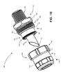
- Fig. 1B is an isometric, schematic view of the electrical cable fitting of Fig. 1A in a partially assembled configuration
- Fig. 1C is a cross-sectional view of the electrical fitting of Fig. 1A in a fully assembled configuration
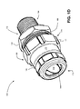
- Fig. 1D is an isometric, schematic view of the electrical cable fitting of Fig. 1A in a fully assembled configuration
- Figs. 2A-2C are schematic, cross-sectional, side, and isometric views, respectively, of an exemplary fitting body of Fig. 1A ;
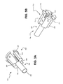
- Figs. 3A and 3B are rear and front isometric views, respectively, of an exemplary sealing cartridge of Fig. 1A ;
- Figs. 4A and 4B are rear and front isometric views, respectively, of an exemplary sealing sleeve of Fig. 1A .
- the described electrical cable fittings may include a main nut, a fitting body, and a hub nut each having a central bore therein.
- an angled tubular sleeve is inserted within the body and a resilient, tubular clamping ring is inserted within the main nut.
- the clamping ring is provided within a tapered or angled configuration designed to engage or interact with an inner surface of the fitting body during assembly of the fitting.
- the angled sleeve is inserted between the braiding and the inner insulator on the prepared cable end until the braiding abuts an end of the sleeve.
- the main nut is then threaded onto the body, causing the clamping ring to be received within the fitting body and further causing the clamping ring to engage the braiding thereby clamping the cable within the fitting between the clamping ring and the conical sleeve.
- a portion of the fitting body may be provided with one or more slots or apertures therein.
- the slots may allow visual inspection of the clamped engagement of the clamping ring, the cable braiding, and the angled sleeve, following assembly of the main nut to the fitting body, but prior to assembly of the hub nut to the main nut.
- Fig. 1A is an exploded cross-sectional view of an exemplary embodiment of an electrical cable fitting 100 consistent with implementations described herein.
- Fig. 1B is an isometric view of cable fitting 100 in a partially assembled configuration.
- Fig. 1C is a cross-sectional view of fitting 100 in an assembled configuration.
- Fig. 1D is an isometric view of cable fitting 100 in an assembled configuration. As illustrated in Figs.
- fitting 100 may include a fitting body 102, a tubular sleeve 104, a clamping ring 106, a main nut 108, a compression bushing 110, a gland nut 112, a sealing sleeve 114, a sealing cartridge 116, a hub nut 118, and an O-ring 120.
- the relative terms “rearward” and “forward” are used to designate various portions or components of fitting 100 in reference to a direction of insertion of an electrical cable therein. It should be understood that these terms are descriptive only and that in some implementations, the terms may be reversed, such as in reference to a removal of the electrical cable from fitting 100.
- fitting body 102 includes an elongated hollow generally tubular member having an enlarged cable receiving end 122, an intermediate portion 124, and a smaller conductor egressing end 126 opposing cable receiving end 122.
- Cable receiving end 122 may include external threads 128 formed thereon for engaging internal threads 129 in main nut 108 in the manner described below.
- Conductor egressing end 126 includes a sleeve receiving portion 130 configured to engage a rearward end 400 of sealing sleeve 114 during assembly of fitting 100.
- Intermediate portion 124 includes an external annular flange 133 and annular rib 135.
- flange 133 may engage a portion of main nut 108 and act as a positive stop during assembly of fitting 100. Further, as shown in Fig. 1B , flange 133 and rib 135 may together engage O-ring 120 to seal fitting 100 from outside environmental moisture.
- Fitting body 102 includes an internal central bore 134 extending along a central longitudinal axis (depicted as a dashed line in Fig. 1A ) between cable receiving end 122 and conductor egressing end 126 for receiving tubular sleeve 104 and clamping ring 106 therein.
- central bore 134 may include an angled annular portion 136 proximate to intermediate portion 124 for engaging clamping ring 106 during assembly of fitting 100.
- Figs. 2A-2C depict cross-sectional, side, and isometric views, respectively, of an exemplary fitting body 102.
- fitting body 102 may include one or more apertures 138 therein (two of which are shown in Fig. 1A ) for enabling visual confirmation of cable clamping within central bore 134.
- Apertures 138 may be spaced apart in a radial configuration to enable visible access to central bore 134 from any of a number of positions about fitting 100, upon insertion of an electrical cable 180 ( Fig. 1C ) into fitting body 102, but prior to insertion of fitting body 102 into hub nut 118.
- apertures 138 may be positioned in line with rib 135. That is, portions of annular rib 135 may be removed to form apertures 138. Any suitable numbers of apertures 138, e.g., three or four apertures 138, may be formed to facilitate efficient visual access to bore 134, e.g., in a full 360° within fitting body 102. In this manner, following insertion of electrical cable 180 within fitting body 102, an examination of a clamping relationship of clamping ring 106 and tubular sleeve 104 may be made via apertures 138.
- annular rib 135 may include a grooved or keyed configuration to mate with a correspondingly grooved portion of hub nut 118 during assembly of fitting 100.
- sleeve receiving portion 130 of fitting body 102 includes an internal tubular portion 140 projecting radially inwardly from central bore 134 and having an inside diameter smaller than the inside diameter of the remainder of fitting body 102.
- a rearward end of internal tubular portion 140 is configured to receive/engage a forward end of tubular sleeve 104 during assembly of fitting 100, as described below.
- the forward end of internal tubular portion 140 includes an annular groove 142 formed therein for receiving rearward end 400 of sealing sleeve 114, as described below.
- the forward end of tubular portion 140 may have an internal diameter sized to receive exposed conductors 181 of electrical cable 180 ( Fig. 1C ) and may have a diameter that is smaller than the outside diameter of a rearward portion of sealing cartridge 116, thus effectively retaining sealing cartridge 116 within sealing sleeve 114 upon assembly (or partial assembly) of fitting 100.
- Tubular sleeve 104 includes a generally cylindrical configuration having rearward cable receiving end 144, and a forward cable egressing end 146 and a central bore 147 formed therethrough.
- cable receiving end 144 includes an angled or beveled configuration.
- cable receiving end 144 may include an angle of approximately 30-60° relative to the axial direction of fitting 100.
- the angled nature of cable receiving end 144 may enable tubular sleeve 104 to become efficiently interposed between conductive braiding 182 and center insulation 184 of electrical cable 180 during assembly of fitting 100.
- the pointed end of cable receiving end 144 may be efficiently driven between braiding 182 and insulation 184 of cable 180, with center insulation 184 (and conductors 181 embedded therein) passing into central bore 147 and braiding 182 passing over the outer surface of tubular sleeve 104.
- Forward cable egressing end 146 includes a flanged base 148 having an outside diameter approximately similar to the inside diameter of intermediate portion 124 of fitting body 102.
- flanged base 148 of tubular sleeve 104 is configured to seat onto the rearward end of internal tubular portion 140 and frictionally engage the internal tubular surface of intermediate portion 124 to retain tubular sleeve 104 within fitting body 102 prior to and during assembly.
- forward cable egressing end 146 further includes a conical outer surface 150 configured to engage clamping ring 106 during final assembly of fitting 100. More particularly, a rearwardmost portion of cable egressing end 146 may have an outside diameter smaller than a forwardmost portion of cable egressing end 146, thereby providing the conical configuration.
- a total length of tubular sleeve 104 may be provided such that the pointed end of cable receiving end 144 of tubular sleeve 104 projects from main nut 108 and gland nut 112 upon final assembly of fitting 100.
- the length of tubular sleeve 104 may be sufficient to cause the point of cable receiving end 144 to project from main nut 108 when fitting 100 is in an intermediate assembled configuration, in which threads 128 in fitting body 102 are threaded with threads 129 in main nut 108.
- electrical cable 180 may be easily inserted into fitting 100, by placing the exposed pointed end of tubular sleeve 104 between the braiding 182 and the insulation 184 of cable 180 and pushing cable 180 forwardly into fitting 100.
- central bore 147 in cable egressing end 146 may include an sealing barrier 152 formed therein.
- integrated sealing barrier 152 may be provided within bore 147 of tubular sleeve 104 and may include a tubular bore 154 formed therein for resiliently receiving a portion of an electrical cable inserted therethrough (see, e.g., conductors 181 of cable 180 in Fig. 1C ).
- sealing barrier 152 may be formed of a resilient material, such as latex, rubber, etc. As described below, during assembly of fitting 100, sealing barrier 152 may engage inserted electrical cable 180 and prevent the injected or distributed sealing compound from flowing into tubular sleeve 104 rearward of barrier 152.
- sealing barrier 152 may be formed or positioned within tubular sleeve 104 prior to assembly of fitting 100, e.g., during the manufacture of tubular sleeve 104.
- Clamping ring 106 includes a forward end 156 and a rearward end 158 and is configured to engage angled portion 136 of fitting body 102 and outer surface 150 of tubular sleeve 104 during assembly of fitting 100 to clampingly engage braiding 182 of cable 180 therebetween.
- clamping ring 106 includes a generally cylindrical configuration formed of a resilient material, such as a plastic, a polymer, or a rubber.
- rearward end 158 of clamping ring 106 includes a outer flange 160 for engaging a corresponding notch 162 in an inner surface of main nut 108 (described below).
- an outside diameter of flange 160 may be slightly larger than an inside diameter of notch 162 in main nut 108, thereby enabling clamping ring 106 to be press-fit into notch 162 prior to final assembly of fitting 100.
- the outside surface of clamping ring 106 may include a tapered or angled configuration, in which an intermediate outside portion 164 includes an outside diameter larger than a forward outside portion 166.
- the inside surface of clamping ring 106 may include an opposing tapered configuration, in which an intermediate inside portion 168 includes an inside diameter that is smaller than an inside diameter of the forward inside portion 170.
- clamping ring 106 may include one or more slots, slits, or holes for enabling clamping ring 106 to deflect or deform inwardly upon bias against angled portion 136 of fitting body 102. For example, a number of axial slots may be formed in forward end 156 of clamping ring 106.
- main nut 108 may include an elongate hollow generally tubular member having a rearward cable receiving end 172, an intermediate portion 173, and a forward end 174.
- rearward cable receiving end 172, intermediate portion 173, and forward end 174 may be formed in a substantially annularly notched configuration, such that rearward cable receiving end 172 has smaller inside and outside diameters than intermediate portion 173, and intermediate portion 173 has smaller inside and outside diameters than forward end 174.
- an inside diameter of rearward cable receiving end 172 may be sized to accommodate electrical cable 180 inserted therethrough.
- An inside diameter of intermediate portion 173 may be sized to accommodate cable receiving end 122 of fitting body 102, as shown in Fig. 1B .
- a shoulder 170 may be formed at an internal transition between rearward cable receiving end 172 and intermediate portion 173. As described briefly above, and as shown in Fig. 1B , shoulder 170 may include notch 162 for receiving and engaging flange 160 in clamping ring 106 rearward end 158.
- rearward cable receiving end 172 of main nut 108 may include external threads 175 formed thereon for engaging internal threads 176 in gland nut 112. Additionally, an axial length of intermediate portion 173 may provide an area for marking certifications and branding. A forward portion of intermediate portion 173 may be provided with internal threads 129 for engaging external threads 128 in fitting body 102 during an intermediate assembly of fitting 100.
- clamping ring 106 may be in an uncompressed state or relaxed state, thereby allowing braiding 182 of electrical cable 180 to be slid or pushed over tubular sleeve 104, as described above, and yet maintain fitting body 102 in a retained relationship with respect to main nut 108.
- Forward end 174 of main nut 108 may include a tool engaging outer surface 177.
- outer surface 177 may include a hexagonal configuration on at least a portion thereof for engaging a torque applying tool, such as a wrench.
- other engagement surfaces may be used, such as knurling, notching, etc.
- forward end 174 of main nut 108 may include internal threads 179 for engaging external threads 186 provided on a rearward end 188 of hub nut 118, during final assembly of fitting 100, as described below.
- gland nut 112 may include a substantially tubular configuration having an forwardly angled inner surface 190 for engaging compression bushing 110 and urging it toward rearward end 172 of main nut 108 upon tightening of gland nut 112 relative to main nut 108, e.g., via an outer tool engaging surface 192 on gland nut 112.
- internal threads 176 are provided in gland nut 112 for engaging external threads 175 in main nut 108 to secure compression bushing 110 within fitting 100.
- compression bushing 110 may include a substantially frustoconically-shaped elastomeric material having a bore 194 therethrough.
- the frustoconical shape may be configured to engage angled surface 190 in gland nut 112.
- an internal diameter of bore 194 may shrink.
- bushing 110, and main nut 108 compression of bushing 110 may seal and secure cable 180 within fitting 100.
- bushing 110 may adapt to retain cables having a variety of sizes.
- Sealing cartridge 116 may have a generally tubular configuration to be received within sealing sleeve 114, as described below.
- Figs. 3A and 3B are front and rear isometric views, respectively, of an exemplary sealing cartridge 116.
- Sealing cartridge 116 may include a central bore 300 formed therethrough, a conductor separating portion 302, and a sealant administration portion 304.
- Conductor separating portion 302 may include an annular shoulder 306 and a number of radially spaced conductor maintaining notches or slots 308 formed axially in a periphery of conductor separating portion 302.
- annular shoulder 306 is formed at a rearward end of cartridge 116 and may be configured to engage a corresponding shoulder portion 404 in sealing sleeve 114, during insertion of sealing cartridge 116 into sealing sleeve 114.
- each of slots 308 may having a generally cylindrical configuration, although other non-cylindrical shapes or cross-sections may also be used.
- conductor separating portion 302 may include a number of rearwardly projecting portions 312 corresponding to the number of slots 308.
- Rearwardly projecting portions 312 may be configured to extend slots 308 beyond an internal length of central bore 300 in cartridge 116, such that a sealant receiving chamber 314 is formed between rearwardly projecting portions 312.
- sealant receiving chamber 314 Upon assembly, sealant receiving chamber 314 is positioned between electrical cable conductors 181 (three of which are shown in Fig. 1C ) received within slots 308. As described below, sealant receiving chamber 314 allows for efficient distribution of sealing compound around and between conductors 181 during assembly of fitting 100.
- sealant administration portion 304 may form a tube for administering a sealing compound (also referred to as a sealant) to sealant receiving chamber 314 via central bore 300.
- a sealing compound also referred to as a sealant
- an outside diameter of sealant administration portion 304 may be sized so as to align with a radially inward portion of slots 308, thereby allowing electrical cable conductors 181 received within slots 308 to lay substantially flat against sealant administration portion 304.
- sealing cartridge 116 may provide a modular mechanism for handling electrical cables having different numbers of conductors in a common fitting design.
- Figs. 4A and 4B are rear and front isometric views of an exemplary sealing sleeve 114.
- sealing sleeve 114 may include rearward end 400 and a forward end 402 having a generally tubular configuration.
- Rearward end 400 may include a shoulder portion 404 having larger inside and outside diameters relative to the remainder of sealing sleeve 114, as described above.
- an inside diameter of shoulder portion 404 may be sized to receive annular shoulder 306 in cartridge 116.
- annular groove 142 in internal tubular portion 140 of fitting body 102 may receive rearward end 400 of sealing sleeve 114.
- an axial length of shoulder portion 404 may be sized substantially similarly to an axial distance from conductor egressing end 126 of fitting body 102 and a rearwardmost portion of annular groove 142.
- an inside diameter of forward end 402 of sealing sleeve 114 may be substantially similar to an outside diameter of conductor separating portion 302 of sealing cartridge 116, such that sealing sleeve 114 may axially receive sealing cartridge 116 upon placement of electrical cable conductors 181 within slots 308.
- electrical cable conductors 181 (extending from central bore 134 in fitting body 102) may be positioned within slots 308 in sealing cartridge 116.
- Cartridge 116 may be seated within sealing sleeve 114, and sealing sleeve 114 may then be axially received within annular groove 142 in internal tubular portion 140 of fitting body 102.
- fitting 100 may be positioned vertically during assembly, such that sealing sleeve 114 and conductors 181 project upwardly from fitting body 102.
- Sealing compound (not shown) may be inserted or injected into central bore 300 via sealant administration portion 304 and allowed to flow into sealant receiving chamber 314, abut sealing barrier 152, and flow around and between electrical cable conductors 181 received within slots 308 while filling sealing sleeve 114.
- the vertical orientation of fitting 100 provides a gravity assisted flow of sealing compound during assembly.
- each of sealing sleeve 114 and sealing cartridge 116 may be formed of a transparent material, such as a transparent plastic, to allow visible confirmation that complete distribution of the sealing compound between and around conductors 181 has been accomplished. Following visual confirmation of such distribution, the fitting body 102 may be secured between hub nut 118 and the main nut 108.
- hub nut 118 may include an elongated hollow generally tubular member that includes rearward end 188, an intermediate portion 195, and a forward end 196. As shown, rearward cable receiving end 188, intermediate portion 195, and forward end 196 may be formed in a substantially annularly notched configuration, such that rearward end 188 has a larger inside diameter than intermediate portion 195, and intermediate portion 195 has larger inside diameter than forward end 196.
- rearward end 188 includes external threads 186 for engaging internal threads 179 in main nut 108. Additionally, as shown in Figs. 1A and 1B , inside diameter of rearward end 188 may include annular rib 197 positioned to correspond with annular rib 135 in fitting body 102 to engage O-ring 120 during assembly of fitting 100.
- Intermediate portion 195 of hub nut 118 may include an inside diameter sized to accommodate forward end 126 of fitting body 102. Further, intermediate portion 195 may include an outer tool engagement surface, such as a hexagonal configuration for engaging a tool during tightening of hub nut 118 relative to main nut 108 or on a housing or other structure (not shown) for receiving fitting 100.
- Forward end 196 of hub nut 118 may include an inside diameter sized to accommodate sealing sleeve 114, as shown in Fig. 1B .
- hub nut 118 may be slid along conductors 181 and onto fitting body 102. External threads 186 in hub nut 118 may then engage internal threads 179 in main nut 108 to secure fitting body 102 and main nut 108 to hub nut 118.
- Tightening of main nut 108 relative to hub nut 118 may cause compression/engagement of clamping ring 106 onto cable braiding 182 of cable 180, thereby securing cable 180 within fitting 100.
- Such engagement may further cause O-ring 120 to be compressed between flange 133 and annular ribs 135/197 thereby effecting a liquid-proof seal between hub nut 118 and fitting body 102.
- forward end 196 of hub nut 118 may further include external threads 198 formed on an outer surface thereof for engaging corresponding threads in a housing (e.g., junction box, transformer, etc.) or other structure for receiving fitting 100.
- a housing e.g., junction box, transformer, etc.
- fitting 100 may be initially provided (e.g., from a manufacturing facility) as a number of pre-assembled sub-assemblies.
- a first sub-assembly may include main nut 108, clamping ring 106, compression bushing 110, and gland nut 112
- a second sub-assembly may include fitting body 102, tubular sleeve 104, O-ring 120, sealing sleeve 114, sealing cartridge 116, and hub nut 118.
- an installer may initially thread a prepared end of cable 180 (e.g., in which a portion of the outer insulator of cable 180 has been removed and conductors 181 extend from an exposed portion of conductive braiding 182 and center insulation 184) through the first sub-assembly and into tubular sleeve 104 of the second sub-assembly. As described above, continued insertion of the cable 180 may cause the angled portion of cable receiving end 144 to separate the braiding 182 from center insulation 184.
- the first sub-assembly may be threaded to the second sub-assembly, such as by engaging threads 129 in fitting body 102 with threads 179 in main nut 108.
- hub nut 118 may be removed from the second sub-assembly to allow visual confirmation that braiding 182 has fully seated within fitting body 102 via apertures 138 in fitting body. Sealant may then be injected into sealing sleeve and permitted to cure and the entire fitting 100 may be fully assembled, by reinstalling hub nut 118 onto fitting body and securing hub nut 118 to main nut 108 via threads 186 in hub nut 118 and threads 179 in main nut 108.
- fitting 100 By providing fitting 100 as two pre-assembled sub-assemblies, field installation may be simplified.
Landscapes
- Installation Of Indoor Wiring (AREA)
- Insulating Bodies (AREA)
Applications Claiming Priority (2)
| Application Number | Priority Date | Filing Date | Title |
|---|---|---|---|
| US201261676036P | 2012-07-26 | 2012-07-26 | |
| US13/826,534 US8979590B2 (en) | 2012-07-26 | 2013-03-14 | Cable gland for electrical cable fitting |
Publications (3)
| Publication Number | Publication Date |
|---|---|
| EP2690736A2 true EP2690736A2 (de) | 2014-01-29 |
| EP2690736A3 EP2690736A3 (de) | 2014-03-05 |
| EP2690736B1 EP2690736B1 (de) | 2020-03-04 |
Family
ID=48874902
Family Applications (1)
| Application Number | Title | Priority Date | Filing Date |
|---|---|---|---|
| EP13178232.8A Active EP2690736B1 (de) | 2012-07-26 | 2013-07-26 | Kabeleinfassung für Elektrokabelarmatur |
Country Status (3)
| Country | Link |
|---|---|
| US (1) | US8979590B2 (de) |
| EP (1) | EP2690736B1 (de) |
| CA (1) | CA2821530C (de) |
Cited By (4)
| Publication number | Priority date | Publication date | Assignee | Title |
|---|---|---|---|---|
| WO2018073580A1 (en) * | 2016-10-18 | 2018-04-26 | Jdr Cable Systems Ltd | Cable termination assembly |
| EP3376620A4 (de) * | 2015-11-12 | 2019-02-20 | Autonetworks Technologies, Ltd. | Dichtungsstruktur für kabel und dichtungselement |
| WO2019220146A1 (en) * | 2018-05-17 | 2019-11-21 | Hubbell Limited | Cable gland |
| CN111788749A (zh) * | 2017-10-18 | 2020-10-16 | 通贝国际有限公司 | 密封剂填充的缆线密封套 |
Families Citing this family (16)
| Publication number | Priority date | Publication date | Assignee | Title |
|---|---|---|---|---|
| SG178839A1 (en) * | 2009-08-21 | 2012-04-27 | Cmp Products Ltd | Filler assembly for cable gland |
| US10193321B2 (en) | 2009-08-21 | 2019-01-29 | Cmp Products Limited | Filler assembly for cable gland |
| BR112015026719B1 (pt) | 2013-04-30 | 2021-11-16 | Schlumberger Technology B. V. | Conjunto de cabeça para um cabo, sistema de fundo de poço, e método para conectar um cabo com uma ferramenta |
| US10923897B2 (en) | 2017-03-20 | 2021-02-16 | Pentair Flow Services Ag | Cable sealing gland |
| US20190109450A1 (en) * | 2017-10-05 | 2019-04-11 | Schlumberger Technology Corporation | Cable termination assembly and processes for making and using same |
| JP6891800B2 (ja) * | 2017-12-22 | 2021-06-18 | 住友電気工業株式会社 | 電力ケーブルの端末構造 |
| TWI694650B (zh) * | 2018-09-11 | 2020-05-21 | 英屬開曼群島商康而富控股股份有限公司 | 具有密封組件的電纜保持裝置 |
| EP3660995B1 (de) | 2018-11-28 | 2023-01-11 | WISKA Hoppmann GmbH | Integral hergestellte kabelverschraubung |
| CN113795453B (zh) * | 2019-01-22 | 2023-10-03 | 邦德派公司 | 三层车辆升降机 |
| US11715944B1 (en) | 2019-01-22 | 2023-08-01 | Titan3 Technology LLC | Expandable cord protector |
| WO2020206627A1 (en) * | 2019-04-10 | 2020-10-15 | 3M Innovative Properties Company | Cable preparation inspection device, system and method |
| GB2589084B (en) * | 2019-11-12 | 2024-08-07 | Hubbell Ltd | Sealing cables |
| US20220128180A1 (en) * | 2020-10-26 | 2022-04-28 | Robroy Industries - Texas, LLC | Transition Adapter |
| US12126152B2 (en) * | 2021-04-29 | 2024-10-22 | APG Vision LLC | Ball mount with integrated cable gland |
| GB2614307B (en) * | 2021-12-24 | 2025-09-03 | Electrix International Ltd | A conduit connection system |
| US12331823B2 (en) * | 2022-05-27 | 2025-06-17 | Schaeffler Technologies AG & Co. KG | Rotary actuator |
Family Cites Families (25)
| Publication number | Priority date | Publication date | Assignee | Title |
|---|---|---|---|---|
| US3552777A (en) | 1968-02-23 | 1971-01-05 | United Air Lines Inc | Self-locking device for couplings |
| US3538488A (en) | 1969-05-20 | 1970-11-03 | Us Navy | Contact member |
| US3603912A (en) | 1969-08-25 | 1971-09-07 | Thomas & Betts Corp | Raceway terminator |
| JPH01294384A (ja) | 1988-05-20 | 1989-11-28 | Yazaki Corp | コネクタ |
| JP2544953Y2 (ja) | 1992-03-06 | 1997-08-20 | 日本エー・エム・ピー株式会社 | コネクタ |
| GB2265765A (en) | 1992-04-04 | 1993-10-06 | Hawke Cable Glands Ltd | Sealed coupling |
| US6984791B1 (en) | 1993-03-19 | 2006-01-10 | Cooper Technologies Company | Visual latching indicator arrangement for an electrical bushing and terminator |
| US6504103B1 (en) | 1993-03-19 | 2003-01-07 | Cooper Industries, Inc. | Visual latching indicator arrangement for an electrical bushing and terminator |
| JP3074433B2 (ja) | 1994-03-17 | 2000-08-07 | 矢崎総業株式会社 | 二重係止確認可能なコネクタ |
| US5556287A (en) | 1994-05-04 | 1996-09-17 | United Technologies Automotive, Inc. | Visual indication of fully seated position of bolt-driven connector |
| JP2905411B2 (ja) | 1994-10-19 | 1999-06-14 | 矢崎総業株式会社 | コネクタ |
| US5780775A (en) | 1997-03-20 | 1998-07-14 | Yu; Tsung-I | Power strip with inspection window |
| US5929383A (en) | 1997-04-07 | 1999-07-27 | Thomas & Betts Corporation | Rotationally unrestrained grounding coupling for external grounding of fittings |
| US6921283B2 (en) | 2001-08-27 | 2005-07-26 | Trompeter Electronics, Inc. | BNC connector having visual indication |
| US6561841B2 (en) | 2001-08-27 | 2003-05-13 | Trompeter Electronics, Inc. | Connector assembly having visual indicator |
| US6836402B1 (en) | 2003-07-02 | 2004-12-28 | Pei-Chin Huang | Transparent window structure for multiple socket |
| US7121903B2 (en) | 2004-09-27 | 2006-10-17 | Yazaki Corporation | Terminal |
| US7182647B2 (en) | 2004-11-24 | 2007-02-27 | Cooper Technologies Company | Visible break assembly including a window to view a power connection |
| US7144279B2 (en) | 2004-12-30 | 2006-12-05 | Homac Mfg. Company | Electrical connector including viewing windows and associated methods |
| US7568933B2 (en) | 2005-03-10 | 2009-08-04 | Honda Motor Co., Ltd. | Connector for providing waterproof connection and method of examining its connection state |
| US7976339B2 (en) | 2007-01-11 | 2011-07-12 | Ideal Industries, Inc. | Cable connector with bushing that permits visual verification |
| US7497723B2 (en) | 2007-06-14 | 2009-03-03 | Nordson Corporation | High-voltage electrical connector with visual indicator |
| US7963782B2 (en) | 2008-02-25 | 2011-06-21 | Cooper Technologies Company | Separable connector system with a position indicator |
| US7914326B2 (en) | 2008-10-13 | 2011-03-29 | Ideal Industries, Inc. | Coaxial cable connector |
| US8408925B2 (en) | 2010-02-03 | 2013-04-02 | Thomas & Betts International, Inc. | Visible open for switchgear assembly |
-
2013
- 2013-03-14 US US13/826,534 patent/US8979590B2/en active Active
- 2013-07-22 CA CA2821530A patent/CA2821530C/en active Active
- 2013-07-26 EP EP13178232.8A patent/EP2690736B1/de active Active
Non-Patent Citations (1)
| Title |
|---|
| None |
Cited By (8)
| Publication number | Priority date | Publication date | Assignee | Title |
|---|---|---|---|---|
| EP3376620A4 (de) * | 2015-11-12 | 2019-02-20 | Autonetworks Technologies, Ltd. | Dichtungsstruktur für kabel und dichtungselement |
| WO2018073580A1 (en) * | 2016-10-18 | 2018-04-26 | Jdr Cable Systems Ltd | Cable termination assembly |
| GB2555113B (en) * | 2016-10-18 | 2020-10-14 | Jdr Cable Systems Ltd | Cable termination assembly |
| CN111788749A (zh) * | 2017-10-18 | 2020-10-16 | 通贝国际有限公司 | 密封剂填充的缆线密封套 |
| CN111788749B (zh) * | 2017-10-18 | 2021-09-28 | 通贝国际有限公司 | 密封剂填充的缆线密封套 |
| WO2019220146A1 (en) * | 2018-05-17 | 2019-11-21 | Hubbell Limited | Cable gland |
| CN112385106A (zh) * | 2018-05-17 | 2021-02-19 | 豪倍有限公司 | 线缆接头 |
| US11929598B2 (en) | 2018-05-17 | 2024-03-12 | Hubbell Limited | Cable gland |
Also Published As
| Publication number | Publication date |
|---|---|
| CA2821530C (en) | 2015-12-01 |
| EP2690736B1 (de) | 2020-03-04 |
| CA2821530A1 (en) | 2014-01-26 |
| US8979590B2 (en) | 2015-03-17 |
| US20140030903A1 (en) | 2014-01-30 |
| EP2690736A3 (de) | 2014-03-05 |
Similar Documents
| Publication | Publication Date | Title |
|---|---|---|
| CA2821530C (en) | Cable gland for electrical cable fitting | |
| US8845361B2 (en) | Explosion-proof electrical fitting | |
| US8777660B2 (en) | Electric connector with a cable clamping portion | |
| US9461452B2 (en) | Cable glands | |
| US7914326B2 (en) | Coaxial cable connector | |
| US5621191A (en) | Cable gland | |
| US9172157B2 (en) | Post-less coaxial cable connector with formable outer conductor | |
| US8944846B2 (en) | Electrical signal connector | |
| US9059580B2 (en) | Curing system for sealing an electrical fitting | |
| US20130023151A1 (en) | Coaxial cable connector with conductive seal | |
| US8137136B1 (en) | Electrical disconnect for hazardous areas | |
| CA2781205A1 (en) | Cable connector with bushing element | |
| US9455526B2 (en) | Conductor connectors for power cables | |
| US7059900B2 (en) | Coaxial cable splice connector assemblies | |
| TWI590538B (zh) | 同軸纜線連接器及其製造方法 | |
| US8986034B2 (en) | Restraint and lock for electrical connector | |
| GB2563901A (en) | Coaxial cable connector |
Legal Events
| Date | Code | Title | Description |
|---|---|---|---|
| PUAI | Public reference made under article 153(3) epc to a published international application that has entered the european phase |
Free format text: ORIGINAL CODE: 0009012 |
|
| AK | Designated contracting states |
Kind code of ref document: A2 Designated state(s): AL AT BE BG CH CY CZ DE DK EE ES FI FR GB GR HR HU IE IS IT LI LT LU LV MC MK MT NL NO PL PT RO RS SE SI SK SM TR |
|
| AX | Request for extension of the european patent |
Extension state: BA ME |
|
| PUAL | Search report despatched |
Free format text: ORIGINAL CODE: 0009013 |
|
| AK | Designated contracting states |
Kind code of ref document: A3 Designated state(s): AL AT BE BG CH CY CZ DE DK EE ES FI FR GB GR HR HU IE IS IT LI LT LU LV MC MK MT NL NO PL PT RO RS SE SI SK SM TR |
|
| AX | Request for extension of the european patent |
Extension state: BA ME |
|
| RIC1 | Information provided on ipc code assigned before grant |
Ipc: H02G 3/06 20060101ALN20140129BHEP Ipc: H02G 15/076 20060101ALI20140129BHEP Ipc: H02G 15/007 20060101ALN20140129BHEP Ipc: H02G 15/04 20060101AFI20140129BHEP |
|
| 17P | Request for examination filed |
Effective date: 20140905 |
|
| RBV | Designated contracting states (corrected) |
Designated state(s): AL AT BE BG CH CY CZ DE DK EE ES FI FR GB GR HR HU IE IS IT LI LT LU LV MC MK MT NL NO PL PT RO RS SE SI SK SM TR |
|
| 17Q | First examination report despatched |
Effective date: 20150225 |
|
| STAA | Information on the status of an ep patent application or granted ep patent |
Free format text: STATUS: EXAMINATION IS IN PROGRESS |
|
| GRAP | Despatch of communication of intention to grant a patent |
Free format text: ORIGINAL CODE: EPIDOSNIGR1 |
|
| RIC1 | Information provided on ipc code assigned before grant |
Ipc: H02G 3/06 20060101ALN20190308BHEP Ipc: H02G 15/04 20060101AFI20190308BHEP Ipc: H02G 15/076 20060101ALI20190308BHEP Ipc: H02G 15/007 20060101ALN20190308BHEP |
|
| STAA | Information on the status of an ep patent application or granted ep patent |
Free format text: STATUS: GRANT OF PATENT IS INTENDED |
|
| RIC1 | Information provided on ipc code assigned before grant |
Ipc: H02G 3/06 20060101ALN20190318BHEP Ipc: H02G 15/076 20060101ALI20190318BHEP Ipc: H02G 15/007 20060101ALN20190318BHEP Ipc: H02G 15/04 20060101AFI20190318BHEP |
|
| RIC1 | Information provided on ipc code assigned before grant |
Ipc: H02G 15/04 20060101AFI20190327BHEP Ipc: H02G 15/076 20060101ALI20190327BHEP Ipc: H02G 3/06 20060101ALN20190327BHEP Ipc: H02G 15/007 20060101ALN20190327BHEP |
|
| INTG | Intention to grant announced |
Effective date: 20190418 |
|
| GRAJ | Information related to disapproval of communication of intention to grant by the applicant or resumption of examination proceedings by the epo deleted |
Free format text: ORIGINAL CODE: EPIDOSDIGR1 |
|
| STAA | Information on the status of an ep patent application or granted ep patent |
Free format text: STATUS: EXAMINATION IS IN PROGRESS |
|
| GRAP | Despatch of communication of intention to grant a patent |
Free format text: ORIGINAL CODE: EPIDOSNIGR1 |
|
| STAA | Information on the status of an ep patent application or granted ep patent |
Free format text: STATUS: GRANT OF PATENT IS INTENDED |
|
| INTC | Intention to grant announced (deleted) | ||
| RIC1 | Information provided on ipc code assigned before grant |
Ipc: H02G 15/007 20060101ALN20190827BHEP Ipc: H02G 15/076 20060101ALI20190827BHEP Ipc: H02G 15/04 20060101AFI20190827BHEP Ipc: H02G 3/06 20060101ALN20190827BHEP |
|
| INTG | Intention to grant announced |
Effective date: 20190911 |
|
| GRAS | Grant fee paid |
Free format text: ORIGINAL CODE: EPIDOSNIGR3 |
|
| GRAJ | Information related to disapproval of communication of intention to grant by the applicant or resumption of examination proceedings by the epo deleted |
Free format text: ORIGINAL CODE: EPIDOSDIGR1 |
|
| GRAL | Information related to payment of fee for publishing/printing deleted |
Free format text: ORIGINAL CODE: EPIDOSDIGR3 |
|
| STAA | Information on the status of an ep patent application or granted ep patent |
Free format text: STATUS: EXAMINATION IS IN PROGRESS |
|
| GRAJ | Information related to disapproval of communication of intention to grant by the applicant or resumption of examination proceedings by the epo deleted |
Free format text: ORIGINAL CODE: EPIDOSDIGR1 |
|
| GRAL | Information related to payment of fee for publishing/printing deleted |
Free format text: ORIGINAL CODE: EPIDOSDIGR3 |
|
| GRAP | Despatch of communication of intention to grant a patent |
Free format text: ORIGINAL CODE: EPIDOSNIGR1 |
|
| GRAR | Information related to intention to grant a patent recorded |
Free format text: ORIGINAL CODE: EPIDOSNIGR71 |
|
| STAA | Information on the status of an ep patent application or granted ep patent |
Free format text: STATUS: GRANT OF PATENT IS INTENDED |
|
| GRAA | (expected) grant |
Free format text: ORIGINAL CODE: 0009210 |
|
| STAA | Information on the status of an ep patent application or granted ep patent |
Free format text: STATUS: THE PATENT HAS BEEN GRANTED |
|
| INTC | Intention to grant announced (deleted) | ||
| RIC1 | Information provided on ipc code assigned before grant |
Ipc: H02G 15/04 20060101AFI20200116BHEP Ipc: H02G 3/06 20060101ALN20200116BHEP Ipc: H02G 15/007 20060101ALN20200116BHEP Ipc: H02G 15/076 20060101ALI20200116BHEP |
|
| RIC1 | Information provided on ipc code assigned before grant |
Ipc: H02G 3/06 20060101ALN20200123BHEP Ipc: H02G 15/04 20060101AFI20200123BHEP Ipc: H02G 15/076 20060101ALI20200123BHEP Ipc: H02G 15/007 20060101ALN20200123BHEP |
|
| AK | Designated contracting states |
Kind code of ref document: B1 Designated state(s): AL AT BE BG CH CY CZ DE DK EE ES FI FR GB GR HR HU IE IS IT LI LT LU LV MC MK MT NL NO PL PT RO RS SE SI SK SM TR |
|
| INTG | Intention to grant announced |
Effective date: 20200127 |
|
| REG | Reference to a national code |
Ref country code: GB Ref legal event code: FG4D |
|
| REG | Reference to a national code |
Ref country code: CH Ref legal event code: EP |
|
| REG | Reference to a national code |
Ref country code: AT Ref legal event code: REF Ref document number: 1241478 Country of ref document: AT Kind code of ref document: T Effective date: 20200315 |
|
| REG | Reference to a national code |
Ref country code: DE Ref legal event code: R096 Ref document number: 602013066401 Country of ref document: DE |
|
| REG | Reference to a national code |
Ref country code: IE Ref legal event code: FG4D |
|
| PG25 | Lapsed in a contracting state [announced via postgrant information from national office to epo] |
Ref country code: FI Free format text: LAPSE BECAUSE OF FAILURE TO SUBMIT A TRANSLATION OF THE DESCRIPTION OR TO PAY THE FEE WITHIN THE PRESCRIBED TIME-LIMIT Effective date: 20200304 Ref country code: RS Free format text: LAPSE BECAUSE OF FAILURE TO SUBMIT A TRANSLATION OF THE DESCRIPTION OR TO PAY THE FEE WITHIN THE PRESCRIBED TIME-LIMIT Effective date: 20200304 Ref country code: NO Free format text: LAPSE BECAUSE OF FAILURE TO SUBMIT A TRANSLATION OF THE DESCRIPTION OR TO PAY THE FEE WITHIN THE PRESCRIBED TIME-LIMIT Effective date: 20200604 |
|
| REG | Reference to a national code |
Ref country code: NL Ref legal event code: MP Effective date: 20200304 |
|
| PG25 | Lapsed in a contracting state [announced via postgrant information from national office to epo] |
Ref country code: GR Free format text: LAPSE BECAUSE OF FAILURE TO SUBMIT A TRANSLATION OF THE DESCRIPTION OR TO PAY THE FEE WITHIN THE PRESCRIBED TIME-LIMIT Effective date: 20200605 Ref country code: BG Free format text: LAPSE BECAUSE OF FAILURE TO SUBMIT A TRANSLATION OF THE DESCRIPTION OR TO PAY THE FEE WITHIN THE PRESCRIBED TIME-LIMIT Effective date: 20200604 Ref country code: HR Free format text: LAPSE BECAUSE OF FAILURE TO SUBMIT A TRANSLATION OF THE DESCRIPTION OR TO PAY THE FEE WITHIN THE PRESCRIBED TIME-LIMIT Effective date: 20200304 Ref country code: LV Free format text: LAPSE BECAUSE OF FAILURE TO SUBMIT A TRANSLATION OF THE DESCRIPTION OR TO PAY THE FEE WITHIN THE PRESCRIBED TIME-LIMIT Effective date: 20200304 Ref country code: SE Free format text: LAPSE BECAUSE OF FAILURE TO SUBMIT A TRANSLATION OF THE DESCRIPTION OR TO PAY THE FEE WITHIN THE PRESCRIBED TIME-LIMIT Effective date: 20200304 |
|
| REG | Reference to a national code |
Ref country code: LT Ref legal event code: MG4D |
|
| PG25 | Lapsed in a contracting state [announced via postgrant information from national office to epo] |
Ref country code: NL Free format text: LAPSE BECAUSE OF FAILURE TO SUBMIT A TRANSLATION OF THE DESCRIPTION OR TO PAY THE FEE WITHIN THE PRESCRIBED TIME-LIMIT Effective date: 20200304 |
|
| PG25 | Lapsed in a contracting state [announced via postgrant information from national office to epo] |
Ref country code: ES Free format text: LAPSE BECAUSE OF FAILURE TO SUBMIT A TRANSLATION OF THE DESCRIPTION OR TO PAY THE FEE WITHIN THE PRESCRIBED TIME-LIMIT Effective date: 20200304 Ref country code: PT Free format text: LAPSE BECAUSE OF FAILURE TO SUBMIT A TRANSLATION OF THE DESCRIPTION OR TO PAY THE FEE WITHIN THE PRESCRIBED TIME-LIMIT Effective date: 20200729 Ref country code: SM Free format text: LAPSE BECAUSE OF FAILURE TO SUBMIT A TRANSLATION OF THE DESCRIPTION OR TO PAY THE FEE WITHIN THE PRESCRIBED TIME-LIMIT Effective date: 20200304 Ref country code: EE Free format text: LAPSE BECAUSE OF FAILURE TO SUBMIT A TRANSLATION OF THE DESCRIPTION OR TO PAY THE FEE WITHIN THE PRESCRIBED TIME-LIMIT Effective date: 20200304 Ref country code: RO Free format text: LAPSE BECAUSE OF FAILURE TO SUBMIT A TRANSLATION OF THE DESCRIPTION OR TO PAY THE FEE WITHIN THE PRESCRIBED TIME-LIMIT Effective date: 20200304 Ref country code: IS Free format text: LAPSE BECAUSE OF FAILURE TO SUBMIT A TRANSLATION OF THE DESCRIPTION OR TO PAY THE FEE WITHIN THE PRESCRIBED TIME-LIMIT Effective date: 20200704 Ref country code: SK Free format text: LAPSE BECAUSE OF FAILURE TO SUBMIT A TRANSLATION OF THE DESCRIPTION OR TO PAY THE FEE WITHIN THE PRESCRIBED TIME-LIMIT Effective date: 20200304 Ref country code: CZ Free format text: LAPSE BECAUSE OF FAILURE TO SUBMIT A TRANSLATION OF THE DESCRIPTION OR TO PAY THE FEE WITHIN THE PRESCRIBED TIME-LIMIT Effective date: 20200304 Ref country code: LT Free format text: LAPSE BECAUSE OF FAILURE TO SUBMIT A TRANSLATION OF THE DESCRIPTION OR TO PAY THE FEE WITHIN THE PRESCRIBED TIME-LIMIT Effective date: 20200304 |
|
| REG | Reference to a national code |
Ref country code: AT Ref legal event code: MK05 Ref document number: 1241478 Country of ref document: AT Kind code of ref document: T Effective date: 20200304 |
|
| REG | Reference to a national code |
Ref country code: DE Ref legal event code: R097 Ref document number: 602013066401 Country of ref document: DE |
|
| PLBE | No opposition filed within time limit |
Free format text: ORIGINAL CODE: 0009261 |
|
| STAA | Information on the status of an ep patent application or granted ep patent |
Free format text: STATUS: NO OPPOSITION FILED WITHIN TIME LIMIT |
|
| PG25 | Lapsed in a contracting state [announced via postgrant information from national office to epo] |
Ref country code: DK Free format text: LAPSE BECAUSE OF FAILURE TO SUBMIT A TRANSLATION OF THE DESCRIPTION OR TO PAY THE FEE WITHIN THE PRESCRIBED TIME-LIMIT Effective date: 20200304 Ref country code: IT Free format text: LAPSE BECAUSE OF FAILURE TO SUBMIT A TRANSLATION OF THE DESCRIPTION OR TO PAY THE FEE WITHIN THE PRESCRIBED TIME-LIMIT Effective date: 20200304 Ref country code: AT Free format text: LAPSE BECAUSE OF FAILURE TO SUBMIT A TRANSLATION OF THE DESCRIPTION OR TO PAY THE FEE WITHIN THE PRESCRIBED TIME-LIMIT Effective date: 20200304 |
|
| 26N | No opposition filed |
Effective date: 20201207 |
|
| PG25 | Lapsed in a contracting state [announced via postgrant information from national office to epo] |
Ref country code: PL Free format text: LAPSE BECAUSE OF FAILURE TO SUBMIT A TRANSLATION OF THE DESCRIPTION OR TO PAY THE FEE WITHIN THE PRESCRIBED TIME-LIMIT Effective date: 20200304 Ref country code: MC Free format text: LAPSE BECAUSE OF FAILURE TO SUBMIT A TRANSLATION OF THE DESCRIPTION OR TO PAY THE FEE WITHIN THE PRESCRIBED TIME-LIMIT Effective date: 20200304 Ref country code: SI Free format text: LAPSE BECAUSE OF FAILURE TO SUBMIT A TRANSLATION OF THE DESCRIPTION OR TO PAY THE FEE WITHIN THE PRESCRIBED TIME-LIMIT Effective date: 20200304 |
|
| REG | Reference to a national code |
Ref country code: CH Ref legal event code: PL |
|
| GBPC | Gb: european patent ceased through non-payment of renewal fee |
Effective date: 20200726 |
|
| REG | Reference to a national code |
Ref country code: BE Ref legal event code: MM Effective date: 20200731 |
|
| PG25 | Lapsed in a contracting state [announced via postgrant information from national office to epo] |
Ref country code: CH Free format text: LAPSE BECAUSE OF NON-PAYMENT OF DUE FEES Effective date: 20200731 Ref country code: LI Free format text: LAPSE BECAUSE OF NON-PAYMENT OF DUE FEES Effective date: 20200731 Ref country code: LU Free format text: LAPSE BECAUSE OF NON-PAYMENT OF DUE FEES Effective date: 20200726 Ref country code: GB Free format text: LAPSE BECAUSE OF NON-PAYMENT OF DUE FEES Effective date: 20200726 |
|
| PG25 | Lapsed in a contracting state [announced via postgrant information from national office to epo] |
Ref country code: BE Free format text: LAPSE BECAUSE OF NON-PAYMENT OF DUE FEES Effective date: 20200731 |
|
| PG25 | Lapsed in a contracting state [announced via postgrant information from national office to epo] |
Ref country code: IE Free format text: LAPSE BECAUSE OF NON-PAYMENT OF DUE FEES Effective date: 20200726 |
|
| PG25 | Lapsed in a contracting state [announced via postgrant information from national office to epo] |
Ref country code: TR Free format text: LAPSE BECAUSE OF FAILURE TO SUBMIT A TRANSLATION OF THE DESCRIPTION OR TO PAY THE FEE WITHIN THE PRESCRIBED TIME-LIMIT Effective date: 20200304 Ref country code: MT Free format text: LAPSE BECAUSE OF FAILURE TO SUBMIT A TRANSLATION OF THE DESCRIPTION OR TO PAY THE FEE WITHIN THE PRESCRIBED TIME-LIMIT Effective date: 20200304 Ref country code: CY Free format text: LAPSE BECAUSE OF FAILURE TO SUBMIT A TRANSLATION OF THE DESCRIPTION OR TO PAY THE FEE WITHIN THE PRESCRIBED TIME-LIMIT Effective date: 20200304 |
|
| PG25 | Lapsed in a contracting state [announced via postgrant information from national office to epo] |
Ref country code: MK Free format text: LAPSE BECAUSE OF FAILURE TO SUBMIT A TRANSLATION OF THE DESCRIPTION OR TO PAY THE FEE WITHIN THE PRESCRIBED TIME-LIMIT Effective date: 20200304 Ref country code: AL Free format text: LAPSE BECAUSE OF FAILURE TO SUBMIT A TRANSLATION OF THE DESCRIPTION OR TO PAY THE FEE WITHIN THE PRESCRIBED TIME-LIMIT Effective date: 20200304 |
|
| REG | Reference to a national code |
Ref country code: DE Ref legal event code: R082 Ref document number: 602013066401 Country of ref document: DE Representative=s name: MAIWALD GMBH, DE Ref country code: DE Ref legal event code: R082 Ref document number: 602013066401 Country of ref document: DE Representative=s name: MAIWALD PATENTANWALTS- UND RECHTSANWALTSGESELL, DE |
|
| PGFP | Annual fee paid to national office [announced via postgrant information from national office to epo] |
Ref country code: DE Payment date: 20250722 Year of fee payment: 13 |
|
| PGFP | Annual fee paid to national office [announced via postgrant information from national office to epo] |
Ref country code: FR Payment date: 20250725 Year of fee payment: 13 |