EP2690785A2 - Verfahren, System und Vorrichtung zum galvanischen Trennen gategesteuerter Vorrichtungen - Google Patents
Verfahren, System und Vorrichtung zum galvanischen Trennen gategesteuerter Vorrichtungen Download PDFInfo
- Publication number
- EP2690785A2 EP2690785A2 EP13177183.4A EP13177183A EP2690785A2 EP 2690785 A2 EP2690785 A2 EP 2690785A2 EP 13177183 A EP13177183 A EP 13177183A EP 2690785 A2 EP2690785 A2 EP 2690785A2
- Authority
- EP
- European Patent Office
- Prior art keywords
- wireless
- gate
- controlled device
- signals
- wireless transceiver
- Prior art date
- Legal status (The legal status is an assumption and is not a legal conclusion. Google has not performed a legal analysis and makes no representation as to the accuracy of the status listed.)
- Granted
Links
Images


Classifications
-
- H—ELECTRICITY
- H03—ELECTRONIC CIRCUITRY
- H03K—PULSE TECHNIQUE
- H03K17/00—Electronic switching or gating, i.e. not by contact-making and –breaking
- H03K17/51—Electronic switching or gating, i.e. not by contact-making and –breaking characterised by the components used
- H03K17/56—Electronic switching or gating, i.e. not by contact-making and –breaking characterised by the components used by the use, as active elements, of semiconductor devices
- H03K17/687—Electronic switching or gating, i.e. not by contact-making and –breaking characterised by the components used by the use, as active elements, of semiconductor devices the devices being field-effect transistors
- H03K17/689—Electronic switching or gating, i.e. not by contact-making and –breaking characterised by the components used by the use, as active elements, of semiconductor devices the devices being field-effect transistors with galvanic isolation between the control circuit and the output circuit
Definitions
- the subject matter described herein relates generally to power systems and, more particularly, to galvanic isolation of gate-controlled devices used in power systems.
- direct current (DC) electrical power is generated from at least one renewable energy source or generated alternating current (AC) electrical power is inverted to DC electrical power and then converted back to AC.
- renewable energy sources may include wind, solar, geothermal, hydro, biomass, and/or any other renewable energy source.
- the DC electrical power must be converted to AC.
- At least some known power systems use a power converter to convert DC power to AC power. In some instances, the converter can be a parallel converter.
- power converters use gate-controlled devices such as, for example, insulated gate bipolar transistors (IGBT), injection-enhanced gate transistors (IEGT), silicon controlled rectifiers (SCR), gate turn off (GTO) thyristors, gate controlled thyristors (GCT), integrated gate commutated thyristors (IGCT), metal -oxide semiconductor field effect transistor (MOSFET), and the like.
- IGBT insulated gate bipolar transistors
- IEGT injection-enhanced gate transistors
- SCR silicon controlled rectifiers
- GTO gate turn off
- GCT gate controlled thyristors
- GCT gate controlled thyristors
- IGCT integrated gate commutated thyristors
- MOSFET metal -oxide semiconductor field effect transistor
- Gate-controlled devices ordinarily utilize a transformer as the galvanic isolation method to deliver the power to the gate drive circuitry of the gate-controlled device
- gate-controlled devices ordinarily utilize a signal isolated by light (such as fiber optic or optocoupler) as the galvanic isolation method to deliver the control signals to/from the gate drive circuitry.
- the galvanic isolation of the control signals utilizing fiber optic or optocoupler is expensive, and has limitations in terms of a tradeoff of the cost vs. performance analysis. For example an optocoupler usually has a voltage limitation making it impractical for high voltage isolation, and in contrast, fiber optics are capable of high voltage isolation but at a higher cost.
- Described herein are embodiments of methods, apparatus and systems for the galvanic isolation of the control signals to and from a gate-controlled device that overcome challenges in the art, some of which are described above.
- a method of galvanic isolation for a gate-controlled device comprises receiving, by a gate-controlled device, wireless receive signals, wherein said wireless receive signals are received by a wireless receiver associated with the gate-controlled device.
- an embodiment of an apparatus for galvanic isolation for an insulated gate bipolar transistor comprises an IGBT and a wireless transceiver associated with the IGBT.
- the wireless transceiver is configured to receive wireless control signals; and transmit wireless transmit signals.
- a system of galvanic isolation for a gate-controlled device comprises at least one gate-controlled device; a first wireless transceiver associated with the at least one gate-controlled device; a control card; and a second wireless transceiver associated with the control card, wherein wireless control signals transmitted by the second wireless transceiver from the control card are received by the first wireless transceiver and used to control the gate-fired device and wherein wireless transmit signals are transmitted by the first wireless transceiver and received by the second wireless transceiver.
- a power generation system includes a power converter system and at least one power generation unit.
- the power generation unit can be a renewable energy power generation unit that generates power from a renewable energy source.
- renewable energy sources may include wind, solar, geothermal, hydro, biomass, and/or any other renewable energy source.
- the power converter system can include a converter coupled to the power generation unit, and an inverter coupled to the converter by a DC bus.
- the inverter is coupled to an electrical distribution network for supplying electrical energy to the network.
- a control system controls the operation of the converter and the inverter.
- the inverter can be a poly-phase apparatus.
- the inverter can include three inverter phases, each phase including a plurality of parallel bridges.
- Each bridge can be comprised of two or more switches coupled together in series.
- these switches can be comprised of one or more gate-controlled devices such as, for example, insulated gate bipolar transistors (IGBT), injection-enhanced gate transistors (IEGT), silicon controlled rectifiers (SCR), gate turn off (GTO) thyristors, gate controlled thyristors (GCT), integrated gate commutated thyristors (IGCT), metal-oxide semiconductor field effect transistor (MOSFET), and the like.
- the control system can control each of the gate-controlled devices.
- FIG. 1 is a schematic diagram of an exemplary power generation system 100 that includes at least one power generation unit 102.
- Power generation unit 102 includes a wind turbine, a solar panel or array, a fuel cell, a geothermal generator, a hydropower generator, and/or any other device that generates electrical power. More specifically, in the exemplary embodiment, power generation unit 102 can be a device that generates direct current (DC) electrical power from at least one renewable energy source. Alternatively, power generation unit 102 is a gas turbine, a steam turbine, and/or any other device that generates DC or alternating current (AC) power from a renewable or non-renewable energy source.
- DC direct current
- AC alternating current
- power generation unit 102 is coupled to a power converter system 104, or a power converter 104.
- DC power generated by power generation unit 102 is transmitted to power converter system 104, and power converter system 104 converts the DC power to AC power.
- the AC power is transmitted to an electrical distribution network 106, or "grid.”
- Power converter system 104 adjusts an amplitude of the voltage and/or current of the converted AC power to an amplitude suitable for electrical distribution network 106, and provides AC power at a frequency and a phase that are substantially equal to the frequency and phase of electrical distribution network 106.
- power converter system 104 provides three phase AC power to electrical distribution network 106.
- power converter system 104 provides single phase AC power or any other number of phases of AC power to electrical distribution network 106.
- power converter system 104 includes a DC to DC, or "boost,” converter 108 and an inverter 110 coupled together by a DC bus 112.
- power converter system 104 may include an AC to DC converter 108 for use in converting AC power received from power generation unit 102 to DC power, and/or any other converter 108 that enables power converter system 104 to function as described herein.
- power converter system 104 does not include converter 108, and inverter 110 is coupled to power generation unit 102 by DC bus 112 and/or by any other device or conductor.
- inverter 110 is a DC to AC inverter 110 that converts DC power received from converter 108 into AC power for transmission to electrical distribution network 106.
- DC bus 112 includes at least one capacitor 114.
- DC bus 112 includes a plurality of capacitors 114 and/or any other electrical power storage devices that enable power converter system 104 to function as described herein. As current is transmitted through power converter system 104, a voltage is generated across DC bus 112 and energy is stored within capacitors 114.
- Power converter system 104 includes a control system 116 coupled to converter 108 and/or to inverter 110.
- control system 116 includes and/or is implemented by at least one processor.
- the processor includes any suitable programmable circuit such as, without limitation, one or more systems and microcontrollers, microprocessors, reduced instruction set circuits (RISC), application specific integrated circuits (ASIC), programmable logic circuits (PLC), field programmable gate arrays (FPGA), and/or any other circuit capable of executing the functions described herein.
- RISC reduced instruction set circuits
- ASIC application specific integrated circuits
- PLC programmable logic circuits
- FPGA field programmable gate arrays
- inverter 110 includes four inverter switches 202 coupled together for each phase of electrical power that power converter system 200 produces.
- inverter 110 includes any suitable number of inverter switches 202 for each phase of electrical power that enables inverter 110 and/or power converter system 200 to function as described herein.
- inverter switches 202 are insulated gate bipolar transistors (IGBTs).
- IGBTs insulated gate bipolar transistors
- inverter switches 202 are any other suitable transistor or any other suitable switching device.
- inverter 110 includes a first inverter phase 204, a second inverter phase 206, and a third inverter phase 208.
- First inverter phase 204 provides AC power corresponding to a first phase of electrical distribution network 106
- second inverter phase 206 provides AC power corresponding to a second phase of electrical distribution network 106
- third inverter phase 208 provides AC power corresponding to a third phase of electrical distribution network 106.
- first inverter phase 204 includes a first phase first bridge 210 and a first phase second bridge 212.
- Each of first phase first bridge 210 and first phase second bridge 212 includes two inverter switches 202 coupled together in series.
- first phase first bridge 210 The series-coupled inverter switches 202 of first phase first bridge 210 are coupled in parallel with the series-coupled inverter switches 202 of first phase second bridge 212 (i.e., first phase first bridge 210 is coupled in parallel with first phase second bridge 212).
- second inverter phase 206 and third inverter phase 208 are configured in a similar manner to first inverter phase 204. Accordingly, second inverter phase 206 includes a second phase first bridge 214 coupled in parallel with a second phase second bridge 216, and third inverter phase 208 includes a third phase first bridge 218 coupled in parallel with a third phase second bridge 220. Each of second phase first bridge 214, second phase second bridge 216, third phase first bridge 218, and third phase second bridge 220 includes two inverter switches 202 coupled together in series. Alternatively, first inverter phase 204, second inverter phase 206, and/or third inverter phase 208 may include any suitable number and/or configuration of bridges and/or inverter switches 202.
- a first phase first conductor 222 is coupled between the two inverter switches 202 of first phase first bridge 210 and a first phase second conductor 224 is coupled between the two inverter switches 202 of first phase second bridge 212.
- First phase first conductor 222 transmits current from first phase first bridge 210 to a first inductor 226 that includes a first winding 228 and a second winding 230.
- a "winding" includes at least one conductor arranged in one or more loops or "turns" such that the winding is substantially shaped as a coil.
- first phase first conductor 222 is coupled to first winding 228 of first inductor 226.
- a current sensor 232 is coupled to first phase first conductor 222 for use in measuring the current transmitted through conductor 222 and through first winding 228.
- First phase second conductor 224 transmits current from first phase second bridge 212 to second winding 230.
- a current sensor 232 is coupled to first phase second conductor 224 for use in measuring the current transmitted through conductor 224 and through second winding 230.
- first winding 228 and second winding 230 are positioned about a common inductor core 234 such that first winding 228 and second winding 230 are magnetically coupled to inductor core 234 when current is transmitted through first winding 228 and second winding 230.
- FIG. 2 illustrates inductor core 234 separated into two components, this is merely for clarity of illustration.
- inductor core 234 can be a single continuous metal or metallic structure, and first winding 228 and second winding 230 can be positioned about separate sections or portions of inductor core 234.
- the dotted lines shown in FIG. 2 indicate that each section of inductor core 234 is connected to, and formed integrally with, each other section.
- An output of first winding 228 and an output of second winding 230 are coupled to a first phase output conductor 236 that transmits current from first winding 228 and second winding 230 to electrical distribution network 106.
- a second phase first conductor 238 is coupled between the two inverter switches 202 of second phase first bridge 214 and a second phase second conductor 240 is coupled between the two inverter switches 202 of second phase second bridge 216.
- Second phase first conductor 238 transmits current from second phase first bridge 214 to a second inductor 242 that includes a first winding 244 and a second winding 246. More specifically, second phase first conductor 238 is coupled to first winding 244 of second inductor 242.
- a current sensor 232 is coupled to second phase first conductor 238 for use in measuring the current transmitted through conductor 238 and through first winding 244.
- Second phase second conductor 240 transmits current from second phase second bridge 216 to second winding 246.
- a current sensor 232 is coupled to second phase second conductor 240 for use in measuring the current transmitted through conductor 240 and through second winding 246.
- first winding 244 and second winding 246 are positioned about a common inductor core 248 such that first winding 244 and second winding 246 are magnetically coupled to inductor core 248 when current is transmitted through first winding 244 and second winding 246.
- An output of first winding 244 and an output of second winding 246 are coupled to a second phase output conductor 250 that transmits current from first winding 244 and second winding 246 to electrical distribution network 106.
- a third phase first conductor 252 is coupled between the two inverter switches 202 of third phase first bridge 218 and a third phase second conductor 254 is coupled between the two inverter switches 202 of third phase second bridge 220.
- Third phase first conductor 252 transmits current from third phase first bridge 218 to a third inductor 256 that includes a first winding 258 and a second winding 260. More specifically, third phase first conductor 252 is coupled to first winding 258 of third inductor 256.
- a current sensor 232 is coupled to third phase first conductor 252 for use in measuring the current transmitted through conductor 252 and through first winding 258.
- Third phase second conductor 254 transmits current from third phase second bridge 220 to second winding 260.
- a current sensor 232 is coupled to third phase second conductor 254 for use in measuring the current transmitted through conductor 254 and through second winding 260.
- first winding 258 and second winding 260 are positioned about a common inductor core 262 such that first winding 258 and second winding 260 are magnetically coupled to inductor core 262 when current is transmitted through first winding 258 and second winding 260.
- An output of first winding 258 and an output of second winding 260 are coupled to a third phase output conductor 264 that transmits current from first winding 258 and second winding 260 to electrical distribution network 106.
- control system 116 can include one or more control cards (not shown in FIG. 1 ) for interfacing with various components of power generation system 100.
- the one or more control cards can interface with one or more gate-controlled devices such as switches 202 ( FIG. 2 ) to send control signals to the gate-controlled devices and to receive condition or status signals from the gate-controlled devices.
- gate-controlled devices such as switches 202 ( FIG. 2 )
- signals to and from the gate-controlled devices are galvanically isolated.
- FIG. 3 illustrates a prior art converter system 300 utilizing gate-controlled devices 302 having signals isolated by light (such as fiber optic or optocoupler) 304 as the galvanic isolation method to deliver the control signals to/from the gate drive circuitry.
- each gate-controlled device 302 having five signals galvanically isolated with light from the main control card 306, and another control card 308 galvanically isolated with light from the main control card 306, for a total of 27 separate control signals galvanically isolated with light from the main control card 306.
- the optocouplers 304 add additional equipment and costs to the system 300 as well as potential failure points.
- each gate-controlled device 302 must be "hard-wired” (e.g., electrically conductive wiring and/or fiber optic cable) from the gate-controlled device 302 to the control card 306, which may be difficult, expensive and add time to the installation process.
- the main control card 306 must also be optically isolated and “hard-wired” to any other control cards 308.
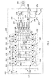
- FIG. 4 illustrates an exemplary converter system 400 utilizing gate-controlled devices 302 with control signals isolated by wireless receivers and transmitters, generally embodied as transceivers 402.
- Mobile cellular phones use various digital modulation schemes, with standard chipsets produced in very high volumes.
- the technology of mobile cellular phones has advanced at this time to provide very low cost chipsets for wireless communication, with nominal data rates between 100 Mbit/s and 1 Gigabit/s.
- These low-cost chipsets combined with algorithms designed to transfer information and extract that information in very noisy environments can be used to provide galvanic isolation for control signals used for a gate-controlled devices 302.
- Ordinary mobile cellular phones available today utilize channel access methods that allow several transmitters to send information simultaneously over a single communication channel, allowing several users to share a band of frequencies.
- These channel access methods can include, for example, frequency division multiple access (FDMA), time-division multiple access (TDMA), spread-spectrum multiple access (SSMA), space-division multiple access (SDMA), and derivatives and/or variants of each.
- FDMA frequency division multiple access
- TDMA time-division multiple access
- SSMA spread-spectrum multiple access
- SDMA space-division multiple access
- CDMA code division multiple access
- CDMA utilizes spread-spectrum technology and a special coding scheme to allow multiple signals to be multiplexed over the same physical channel. CDMA effectively rejects narrow band interference, and is resistant to multipath interference.
- FIG. 4 illustrates a system 400 for galvanic isolation for a gate-controlled device 302.
- One embodiment of the system 400 comprises at least one gate-controlled device 302, a first wireless transceiver 402 associated with the at least one gate-controlled device 302; a control card 306; and a second wireless transceiver 404 associated with the control card 306.
- Wireless control signals transmitted by the second wireless transceiver 404 from the control card 306 are received by the first wireless transceiver 402 and used to control the gate-fired device 302 and wherein wireless transmit signals are transmitted by the first wireless transceiver 402 and received by the second wireless transceiver 402.
- Embodiments of the system 400 may optionally comprise one or more additional control cards 308 having a third wireless transceiver 406 associated with the one or more additional control cards.
- the third wireless transceiver 406 may communicate with the second wireless transceiver of the main control card 404 and/or with the first wireless transceiver 402 associated with the gate-controlled device 302.
- separate receivers and transmitters may replace one or more of the wireless transceivers 402, 404, 406. Therefore, as used herein, "wireless transceiver" is intended to encompass a singular device that operates as a radio frequency (RF) receiver and transmitter or a separate RF receiver and a separate RF transmitter that are associated with a single device such as a gate-controlled device 302.
- RF radio frequency
- the gate-controlled device 302 can include an insulated gate bipolar transistor (IGBT), injection-enhanced gate transistor (IEGT), silicon controlled rectifier (SCR), gate turn off (GTO) thyristor, gate controlled thyristor (GCT), integrated gate commutated thyristor (IGCT), or metal-oxide semiconductor field effect transistor (MOSFET), and the like, or combinations thereof if there are a plurality of gate-controlled devices 302.
- IGBT insulated gate bipolar transistor
- IEGT injection-enhanced gate transistor
- SCR silicon controlled rectifier
- GTO gate turn off
- GCT gate controlled thyristor
- IGCT gate controlled thyristor
- IGCT integrated gate commutated thyristor
- MOSFET metal-oxide semiconductor field effect transistor
- the wireless transmit signals transmitted from the gate-controlled device 302 can comprise one or more of voltage sensing, temperature sensing, current sensing, desaturation sensing signals and the like.
- the wireless transceivers such as the first wireless transceiver 402, the second wireless transceiver 404 and the third wireless transceiver 406 transmit and receive signals using digital wireless technology including code division multiple access (CDMA) as a channel access method.
- CDMA code division multiple access
- the wireless transceivers 402, 404, 406 may use frequency division multiple access (FDMA), time-division multiple access (TDMA), spread-spectrum multiple access (SSMA), space-division multiple access (SDMA), and derivatives and/or variants of each as the channel access method.
- FDMA frequency division multiple access
- TDMA time-division multiple access
- SSMA spread-spectrum multiple access
- SDMA space-division multiple access
- the gate-controlled device 302 comprises an IGBT.
- the IGBT with an associated wireless transceiver 402 can comprise an apparatus for galvanic isolation of the IGBT.
- the wireless transceiver can be configured to receive wireless control signals; and transmit wireless transmit signals.
- the wireless transceivers 402, 404, 406 need shielding from interference such as electromagnetic interference (EMI).
- EMI electromagnetic interference
- the use of cellular technology chipsets may require avoiding interference to and from the ambient electromagnetic environment outside of the wind turbine.
- Most channel access methods are already required to adhere to strict standards and specifications developed by the wireless communications industry, and the EMI signature of the power conversion equipment is already designed with this in mind.
- the crisp signature(s) associated with the carrier frequency (or frequencies) of the wireless transmissions described herein must be attenuated in order to meet codes and regulations.
- FIG. 5 is a schematic view of an exemplary wind turbine generator 500.
- the wind turbine 500 includes a nacelle 502 housing a generator (not shown in FIG. 5 ).
- Nacelle 502 is mounted on a mast 504 (a portion of mast 504 being shown in FIG. 5 .
- Mast 504 may be any height that facilitates operation of wind turbine 500 as described herein.
- Wind turbine 500 also includes a rotor 506 that includes three rotor blades 508 attached to a rotating hub 510.
- wind turbine 500 includes any number of blades 508 that facilitate operation of wind turbine 500 as described herein.
- a typical location for a power converter for a wind turbine generator 500 that can benefit from embodiments of the present invention is near the base of the tower mast 504 of the wind turbine 500 shown in FIG. 5 .
- both the metal cabinet of the power converter as well as the tower mast 504 structure can contribute to shield the high frequency energy of the wireless transmissions described herein to and from the outside world.
- FIG. 6A is an exemplary flowchart illustrating an embodiment of a method of galvanic isolation for a gate-controlled device.
- the process comprises step 602, receiving, by a gate-controlled device, wireless receive signals, wherein said wireless receive signals are received by a wireless receiver associated with the gate-controlled device.
- FIG. 6B is an exemplary flowchart illustrating another embodiment of a method of galvanic isolation for a gate-controlled device.
- the process comprises step 604, receiving, by a gate-controlled device, wireless control signals, wherein the wireless control signals are received by a wireless transceiver associated with the gate-controlled device.
- the gate-controlled device can includes an insulated gate bipolar transistor (IGBT), injection-enhanced gate transistor (IEGT), silicon controlled rectifier (SCR), gate turn off (GTO) thyristor, gate controlled thyristor (GCT), integrated gate commutated thyristor (IGCT), metal-oxide semiconductor field effect transistor (MOSFET), and the like.
- IGBT insulated gate bipolar transistor
- IEGT injection-enhanced gate transistor
- SCR silicon controlled rectifier
- GTO gate turn off
- GCT gate controlled thyristor
- IGCT gate controlled thyristor
- IGCT integrated gate commutated thyristor
- the wireless control signals are received from a main control card having a wireless transmitter.
- the wireless control signals are received by a wireless transceiver utilizing digital wireless technology such as CDMA, FDMA, TDMA, SSMA, and derivatives and/or variants of each as the channel access method, and the like.
- the gate-controlled device is controlled in accordance with the received wireless control signals.
- wireless transmit signals are transmitted by the gate-controlled device, wherein the wireless transmit signals are transmitted by the wireless transceiver associated with the gate-controlled device.
- the wireless transmit signals comprise one or more of voltage sensing, temperature sensing, current sensing, desaturation sensing signals, and the like.
- the wireless transmit signals are transmitted to a main control card having a wireless receiver.
- the wireless transmit signals are transmitted to a main control card having a wireless transceiver utilizing digital wireless technology such as CDMA, FDMA, TDMA, SSMA, and derivatives and/or variants of each as the channel access method, and the like.
- a technical effect of the systems and methods described herein may include at least one of providing a solution to galvanically isolate control signals to a gate-controlled device, particularly in a power generation environment.
Landscapes
- Inverter Devices (AREA)
- Power Conversion In General (AREA)
Applications Claiming Priority (1)
| Application Number | Priority Date | Filing Date | Title |
|---|---|---|---|
| US13/558,864 US9002265B2 (en) | 2012-07-26 | 2012-07-26 | Method, system and apparatus for galvanic isolation of gate-controlled devices |
Publications (3)
| Publication Number | Publication Date |
|---|---|
| EP2690785A2 true EP2690785A2 (de) | 2014-01-29 |
| EP2690785A3 EP2690785A3 (de) | 2014-12-31 |
| EP2690785B1 EP2690785B1 (de) | 2019-03-13 |
Family
ID=48874804
Family Applications (1)
| Application Number | Title | Priority Date | Filing Date |
|---|---|---|---|
| EP13177183.4A Active EP2690785B1 (de) | 2012-07-26 | 2013-07-19 | Verfahren, System und Vorrichtung zum galvanischen Trennen gategesteuerter Vorrichtungen |
Country Status (2)
| Country | Link |
|---|---|
| US (1) | US9002265B2 (de) |
| EP (1) | EP2690785B1 (de) |
Cited By (3)
| Publication number | Priority date | Publication date | Assignee | Title |
|---|---|---|---|---|
| DK201400640A1 (en) * | 2014-11-04 | 2016-05-17 | Wind Solutions As Kk | Monitoring unit for a power converter |
| EP3352363A4 (de) * | 2015-09-18 | 2019-05-01 | Kabushiki Kaisha Toshiba | Steuerungsvorrichtung für leistungswandler |
| EP3866333A1 (de) * | 2020-02-14 | 2021-08-18 | Hamilton Sundstrand Corporation | Steuerungselektronik mit faseroptischer multiplexierung mit geteilter leistung |
Families Citing this family (5)
| Publication number | Priority date | Publication date | Assignee | Title |
|---|---|---|---|---|
| US9595889B2 (en) * | 2013-02-15 | 2017-03-14 | Eaton Corporation | System and method for single-phase and three-phase current determination in power converters and inverters |
| US9057353B2 (en) * | 2013-03-15 | 2015-06-16 | Michael S. Aubuchon, Sr. | Shaft-less radial vane turbine generator |
| EP3167466B1 (de) * | 2014-07-09 | 2024-08-21 | Auckland UniServices Limited | Induktives stromversorgungssystem für elektrofahrzeuge |
| DK4113821T3 (da) * | 2016-11-23 | 2024-10-21 | Kimidrive Llc | Pakkebaseret netværk af drivenheder med variabel frekvens |
| US11670967B1 (en) | 2022-05-09 | 2023-06-06 | Hamilton Sundstrand Corporation | Multi-environmental circuit devices |
Family Cites Families (16)
| Publication number | Priority date | Publication date | Assignee | Title |
|---|---|---|---|---|
| EP0661862A1 (de) | 1993-12-15 | 1995-07-05 | International Business Machines Corporation | Koppeleinrichtung zum Übertragen von Daten zwischen einer DUE bzw. einem Computer und einem öffentlichen Fernsprechwahlnetz, mit einem infrarot-Sender und -Empfänger, sowie einem Sigma-Delta Coder |
| US7417554B2 (en) | 2004-10-12 | 2008-08-26 | Gaton Corporation | Wireless system for one or more electrical switching apparatus |
| US7253602B2 (en) | 2004-10-12 | 2007-08-07 | Eaton Corporation | Self-powered power bus sensor employing wireless communication |
| WO2006069568A1 (en) | 2004-12-27 | 2006-07-06 | Danfoss Drives A/S | Method for detecting earth-fault conditions in motor a controller |
| US7565253B2 (en) | 2005-09-01 | 2009-07-21 | Hubbell Incorporated | High-voltage power supply control system and wireless controller and method therefor |
| US7598625B2 (en) | 2007-06-08 | 2009-10-06 | Honeywell International Inc. | Network-based aircraft secondary electric power distribution system |
| DE102007032179A1 (de) * | 2007-07-10 | 2009-01-22 | Repower Systems Ag | Windenergieanlage mit erweitertem Drehzahlbereich |
| KR100973587B1 (ko) | 2008-01-02 | 2010-08-02 | 한국과학기술원 | 다중 홉 직교주파수분할다중접속 기반무선접속통신시스템에서 cdma코드를 이용한 자원 요청및 할당방법 |
| US7956566B2 (en) * | 2008-01-22 | 2011-06-07 | International Rectifier Corporation | Driver IC with HV-isolation, especially hybrid electric vehicle motor drive concept |
| GB2456823B (en) | 2008-01-25 | 2013-07-24 | Control Tech Ltd | A DC motor drive |
| US20100270859A1 (en) * | 2009-04-24 | 2010-10-28 | Zhengda Gong | Distributed Ultracapacitor Monitoring System Based on iCAN Protocol |
| US8203232B2 (en) | 2009-12-10 | 2012-06-19 | Lear Corporation | Embedded wireless communications for electronic control unit having multiple ground references |
| US20120033392A1 (en) | 2010-08-09 | 2012-02-09 | Tyco Electronics Corporation | Modular Junction Box for a Photovoltaic Module |
| US8493893B2 (en) * | 2011-03-30 | 2013-07-23 | Cognipower, Llc | Single-transformer full-duplex digital isolator |
| US8611107B2 (en) * | 2011-04-27 | 2013-12-17 | Solarbridge Technologies, Inc. | Method and system for controlling a multi-stage power inverter |
| US9442478B2 (en) * | 2011-11-30 | 2016-09-13 | Infineon Technologies Ag | Systems, circuits and a method for generating a configurable feedback |
-
2012
- 2012-07-26 US US13/558,864 patent/US9002265B2/en active Active
-
2013
- 2013-07-19 EP EP13177183.4A patent/EP2690785B1/de active Active
Non-Patent Citations (1)
| Title |
|---|
| None |
Cited By (5)
| Publication number | Priority date | Publication date | Assignee | Title |
|---|---|---|---|---|
| DK201400640A1 (en) * | 2014-11-04 | 2016-05-17 | Wind Solutions As Kk | Monitoring unit for a power converter |
| US10969440B2 (en) | 2014-11-04 | 2021-04-06 | Kk Wind Solutions A/S | Monitoring unit for a power converter |
| EP3352363A4 (de) * | 2015-09-18 | 2019-05-01 | Kabushiki Kaisha Toshiba | Steuerungsvorrichtung für leistungswandler |
| EP3866333A1 (de) * | 2020-02-14 | 2021-08-18 | Hamilton Sundstrand Corporation | Steuerungselektronik mit faseroptischer multiplexierung mit geteilter leistung |
| US11121773B2 (en) | 2020-02-14 | 2021-09-14 | Hamilton Sundstrand Corporation | Split power-control electronics with fiber-optic multiplexing |
Also Published As
| Publication number | Publication date |
|---|---|
| EP2690785A3 (de) | 2014-12-31 |
| US9002265B2 (en) | 2015-04-07 |
| US20140030984A1 (en) | 2014-01-30 |
| EP2690785B1 (de) | 2019-03-13 |
Similar Documents
| Publication | Publication Date | Title |
|---|---|---|
| EP2690785B1 (de) | Verfahren, System und Vorrichtung zum galvanischen Trennen gategesteuerter Vorrichtungen | |
| Musasa et al. | Review on DC collection grids for offshore wind farms with high‐voltage DC transmission system | |
| EP2904682B1 (de) | System mit leistungselektronik zur gewinnung von gleichstrom mit mittlerer spannung | |
| US8050067B2 (en) | Method and control system for controlling power conversion in a power converter | |
| AU2009226528B2 (en) | A power feedback device | |
| EP2372862A2 (de) | Gleichstromübertragungssystem für Fernsolarfarmen | |
| Parker et al. | Cost and losses associated with offshore wind farm collection networks which centralise the turbine power electronic converters | |
| EP2290799A1 (de) | Bidirektionale mehrstufige AC-DC Wandleranordnungen | |
| EP2528180A2 (de) | Verfahren und Systeme zur Gleichstromleistungsübertragung | |
| EP2067229B1 (de) | Umsetzung von wechselspannungsleitungen in hvdc-leitungen | |
| US10153642B2 (en) | Multiphase generator-conversion systems | |
| CA2818149C (en) | Power converter and method of assembling the same | |
| Sano et al. | A boost conversion system consisting of multiple DC-DC converter modules for interfacing wind farms and HVDC transmission | |
| EP2747268B1 (de) | Spannungsgeführter und stromgeregelter Multilevelumrichter | |
| CN102299619B (zh) | 一种用于柔性直流输电阀子模块控制器的电磁抗干扰装置 | |
| CN107117059B (zh) | 电动汽车车载端充电装置、电动汽车 | |
| CN218071476U (zh) | 一种变压器磁耦合隔离装置 | |
| WO2014044561A1 (en) | Direct current power transmission networks operating at different voltages | |
| US9647571B2 (en) | Internal inverter communications | |
| US20140029322A1 (en) | Electric power converter and method for operating the same | |
| JP6987315B1 (ja) | 電力変換装置 | |
| JP2019041477A (ja) | 分散電源システムの制御装置、分散電源システム、分散電源システムの制御方法、及び分散電源システムの制御プログラム | |
| CN102882199A (zh) | 一种高速自关断器件的短路故障限流器 | |
| Shah et al. | PMSG based single active bridge interfaced grid tied off-shore wind energy conversion system | |
| RU2008142754A (ru) | Система для выработки электрической энергии |
Legal Events
| Date | Code | Title | Description |
|---|---|---|---|
| PUAI | Public reference made under article 153(3) epc to a published international application that has entered the european phase |
Free format text: ORIGINAL CODE: 0009012 |
|
| AK | Designated contracting states |
Kind code of ref document: A2 Designated state(s): AL AT BE BG CH CY CZ DE DK EE ES FI FR GB GR HR HU IE IS IT LI LT LU LV MC MK MT NL NO PL PT RO RS SE SI SK SM TR |
|
| AX | Request for extension of the european patent |
Extension state: BA ME |
|
| PUAL | Search report despatched |
Free format text: ORIGINAL CODE: 0009013 |
|
| AK | Designated contracting states |
Kind code of ref document: A3 Designated state(s): AL AT BE BG CH CY CZ DE DK EE ES FI FR GB GR HR HU IE IS IT LI LT LU LV MC MK MT NL NO PL PT RO RS SE SI SK SM TR |
|
| AX | Request for extension of the european patent |
Extension state: BA ME |
|
| RIC1 | Information provided on ipc code assigned before grant |
Ipc: H03K 17/689 20060101AFI20141126BHEP |
|
| 17P | Request for examination filed |
Effective date: 20150630 |
|
| RBV | Designated contracting states (corrected) |
Designated state(s): AL AT BE BG CH CY CZ DE DK EE ES FI FR GB GR HR HU IE IS IT LI LT LU LV MC MK MT NL NO PL PT RO RS SE SI SK SM TR |
|
| STAA | Information on the status of an ep patent application or granted ep patent |
Free format text: STATUS: EXAMINATION IS IN PROGRESS |
|
| 17Q | First examination report despatched |
Effective date: 20170321 |
|
| GRAP | Despatch of communication of intention to grant a patent |
Free format text: ORIGINAL CODE: EPIDOSNIGR1 |
|
| STAA | Information on the status of an ep patent application or granted ep patent |
Free format text: STATUS: GRANT OF PATENT IS INTENDED |
|
| INTG | Intention to grant announced |
Effective date: 20180827 |
|
| GRAS | Grant fee paid |
Free format text: ORIGINAL CODE: EPIDOSNIGR3 |
|
| GRAA | (expected) grant |
Free format text: ORIGINAL CODE: 0009210 |
|
| STAA | Information on the status of an ep patent application or granted ep patent |
Free format text: STATUS: THE PATENT HAS BEEN GRANTED |
|
| AK | Designated contracting states |
Kind code of ref document: B1 Designated state(s): AL AT BE BG CH CY CZ DE DK EE ES FI FR GB GR HR HU IE IS IT LI LT LU LV MC MK MT NL NO PL PT RO RS SE SI SK SM TR |
|
| REG | Reference to a national code |
Ref country code: GB Ref legal event code: FG4D |
|
| REG | Reference to a national code |
Ref country code: CH Ref legal event code: EP Ref country code: AT Ref legal event code: REF Ref document number: 1109077 Country of ref document: AT Kind code of ref document: T Effective date: 20190315 |
|
| REG | Reference to a national code |
Ref country code: IE Ref legal event code: FG4D |
|
| REG | Reference to a national code |
Ref country code: DE Ref legal event code: R096 Ref document number: 602013052165 Country of ref document: DE |
|
| REG | Reference to a national code |
Ref country code: NL Ref legal event code: MP Effective date: 20190313 |
|
| REG | Reference to a national code |
Ref country code: LT Ref legal event code: MG4D |
|
| PG25 | Lapsed in a contracting state [announced via postgrant information from national office to epo] |
Ref country code: NO Free format text: LAPSE BECAUSE OF FAILURE TO SUBMIT A TRANSLATION OF THE DESCRIPTION OR TO PAY THE FEE WITHIN THE PRESCRIBED TIME-LIMIT Effective date: 20190613 Ref country code: SE Free format text: LAPSE BECAUSE OF FAILURE TO SUBMIT A TRANSLATION OF THE DESCRIPTION OR TO PAY THE FEE WITHIN THE PRESCRIBED TIME-LIMIT Effective date: 20190313 Ref country code: FI Free format text: LAPSE BECAUSE OF FAILURE TO SUBMIT A TRANSLATION OF THE DESCRIPTION OR TO PAY THE FEE WITHIN THE PRESCRIBED TIME-LIMIT Effective date: 20190313 Ref country code: LT Free format text: LAPSE BECAUSE OF FAILURE TO SUBMIT A TRANSLATION OF THE DESCRIPTION OR TO PAY THE FEE WITHIN THE PRESCRIBED TIME-LIMIT Effective date: 20190313 |
|
| PG25 | Lapsed in a contracting state [announced via postgrant information from national office to epo] |
Ref country code: LV Free format text: LAPSE BECAUSE OF FAILURE TO SUBMIT A TRANSLATION OF THE DESCRIPTION OR TO PAY THE FEE WITHIN THE PRESCRIBED TIME-LIMIT Effective date: 20190313 Ref country code: NL Free format text: LAPSE BECAUSE OF FAILURE TO SUBMIT A TRANSLATION OF THE DESCRIPTION OR TO PAY THE FEE WITHIN THE PRESCRIBED TIME-LIMIT Effective date: 20190313 Ref country code: HR Free format text: LAPSE BECAUSE OF FAILURE TO SUBMIT A TRANSLATION OF THE DESCRIPTION OR TO PAY THE FEE WITHIN THE PRESCRIBED TIME-LIMIT Effective date: 20190313 Ref country code: GR Free format text: LAPSE BECAUSE OF FAILURE TO SUBMIT A TRANSLATION OF THE DESCRIPTION OR TO PAY THE FEE WITHIN THE PRESCRIBED TIME-LIMIT Effective date: 20190614 Ref country code: BG Free format text: LAPSE BECAUSE OF FAILURE TO SUBMIT A TRANSLATION OF THE DESCRIPTION OR TO PAY THE FEE WITHIN THE PRESCRIBED TIME-LIMIT Effective date: 20190613 Ref country code: RS Free format text: LAPSE BECAUSE OF FAILURE TO SUBMIT A TRANSLATION OF THE DESCRIPTION OR TO PAY THE FEE WITHIN THE PRESCRIBED TIME-LIMIT Effective date: 20190313 |
|
| REG | Reference to a national code |
Ref country code: AT Ref legal event code: MK05 Ref document number: 1109077 Country of ref document: AT Kind code of ref document: T Effective date: 20190313 |
|
| PG25 | Lapsed in a contracting state [announced via postgrant information from national office to epo] |
Ref country code: PT Free format text: LAPSE BECAUSE OF FAILURE TO SUBMIT A TRANSLATION OF THE DESCRIPTION OR TO PAY THE FEE WITHIN THE PRESCRIBED TIME-LIMIT Effective date: 20190713 Ref country code: AL Free format text: LAPSE BECAUSE OF FAILURE TO SUBMIT A TRANSLATION OF THE DESCRIPTION OR TO PAY THE FEE WITHIN THE PRESCRIBED TIME-LIMIT Effective date: 20190313 Ref country code: ES Free format text: LAPSE BECAUSE OF FAILURE TO SUBMIT A TRANSLATION OF THE DESCRIPTION OR TO PAY THE FEE WITHIN THE PRESCRIBED TIME-LIMIT Effective date: 20190313 Ref country code: IT Free format text: LAPSE BECAUSE OF FAILURE TO SUBMIT A TRANSLATION OF THE DESCRIPTION OR TO PAY THE FEE WITHIN THE PRESCRIBED TIME-LIMIT Effective date: 20190313 Ref country code: EE Free format text: LAPSE BECAUSE OF FAILURE TO SUBMIT A TRANSLATION OF THE DESCRIPTION OR TO PAY THE FEE WITHIN THE PRESCRIBED TIME-LIMIT Effective date: 20190313 Ref country code: RO Free format text: LAPSE BECAUSE OF FAILURE TO SUBMIT A TRANSLATION OF THE DESCRIPTION OR TO PAY THE FEE WITHIN THE PRESCRIBED TIME-LIMIT Effective date: 20190313 Ref country code: SK Free format text: LAPSE BECAUSE OF FAILURE TO SUBMIT A TRANSLATION OF THE DESCRIPTION OR TO PAY THE FEE WITHIN THE PRESCRIBED TIME-LIMIT Effective date: 20190313 Ref country code: CZ Free format text: LAPSE BECAUSE OF FAILURE TO SUBMIT A TRANSLATION OF THE DESCRIPTION OR TO PAY THE FEE WITHIN THE PRESCRIBED TIME-LIMIT Effective date: 20190313 |
|
| PG25 | Lapsed in a contracting state [announced via postgrant information from national office to epo] |
Ref country code: SM Free format text: LAPSE BECAUSE OF FAILURE TO SUBMIT A TRANSLATION OF THE DESCRIPTION OR TO PAY THE FEE WITHIN THE PRESCRIBED TIME-LIMIT Effective date: 20190313 Ref country code: PL Free format text: LAPSE BECAUSE OF FAILURE TO SUBMIT A TRANSLATION OF THE DESCRIPTION OR TO PAY THE FEE WITHIN THE PRESCRIBED TIME-LIMIT Effective date: 20190313 |
|
| REG | Reference to a national code |
Ref country code: DE Ref legal event code: R097 Ref document number: 602013052165 Country of ref document: DE |
|
| PG25 | Lapsed in a contracting state [announced via postgrant information from national office to epo] |
Ref country code: AT Free format text: LAPSE BECAUSE OF FAILURE TO SUBMIT A TRANSLATION OF THE DESCRIPTION OR TO PAY THE FEE WITHIN THE PRESCRIBED TIME-LIMIT Effective date: 20190313 Ref country code: IS Free format text: LAPSE BECAUSE OF FAILURE TO SUBMIT A TRANSLATION OF THE DESCRIPTION OR TO PAY THE FEE WITHIN THE PRESCRIBED TIME-LIMIT Effective date: 20190713 |
|
| PLBE | No opposition filed within time limit |
Free format text: ORIGINAL CODE: 0009261 |
|
| STAA | Information on the status of an ep patent application or granted ep patent |
Free format text: STATUS: NO OPPOSITION FILED WITHIN TIME LIMIT |
|
| PG25 | Lapsed in a contracting state [announced via postgrant information from national office to epo] |
Ref country code: DK Free format text: LAPSE BECAUSE OF FAILURE TO SUBMIT A TRANSLATION OF THE DESCRIPTION OR TO PAY THE FEE WITHIN THE PRESCRIBED TIME-LIMIT Effective date: 20190313 |
|
| 26N | No opposition filed |
Effective date: 20191216 |
|
| PG25 | Lapsed in a contracting state [announced via postgrant information from national office to epo] |
Ref country code: SI Free format text: LAPSE BECAUSE OF FAILURE TO SUBMIT A TRANSLATION OF THE DESCRIPTION OR TO PAY THE FEE WITHIN THE PRESCRIBED TIME-LIMIT Effective date: 20190313 Ref country code: MC Free format text: LAPSE BECAUSE OF FAILURE TO SUBMIT A TRANSLATION OF THE DESCRIPTION OR TO PAY THE FEE WITHIN THE PRESCRIBED TIME-LIMIT Effective date: 20190313 |
|
| REG | Reference to a national code |
Ref country code: CH Ref legal event code: PL |
|
| GBPC | Gb: european patent ceased through non-payment of renewal fee |
Effective date: 20190719 |
|
| PG25 | Lapsed in a contracting state [announced via postgrant information from national office to epo] |
Ref country code: TR Free format text: LAPSE BECAUSE OF FAILURE TO SUBMIT A TRANSLATION OF THE DESCRIPTION OR TO PAY THE FEE WITHIN THE PRESCRIBED TIME-LIMIT Effective date: 20190313 |
|
| REG | Reference to a national code |
Ref country code: BE Ref legal event code: MM Effective date: 20190731 |
|
| PG25 | Lapsed in a contracting state [announced via postgrant information from national office to epo] |
Ref country code: GB Free format text: LAPSE BECAUSE OF NON-PAYMENT OF DUE FEES Effective date: 20190719 |
|
| PG25 | Lapsed in a contracting state [announced via postgrant information from national office to epo] |
Ref country code: LU Free format text: LAPSE BECAUSE OF NON-PAYMENT OF DUE FEES Effective date: 20190719 Ref country code: BE Free format text: LAPSE BECAUSE OF NON-PAYMENT OF DUE FEES Effective date: 20190731 Ref country code: CH Free format text: LAPSE BECAUSE OF NON-PAYMENT OF DUE FEES Effective date: 20190731 Ref country code: LI Free format text: LAPSE BECAUSE OF NON-PAYMENT OF DUE FEES Effective date: 20190731 |
|
| PG25 | Lapsed in a contracting state [announced via postgrant information from national office to epo] |
Ref country code: FR Free format text: LAPSE BECAUSE OF NON-PAYMENT OF DUE FEES Effective date: 20190731 |
|
| PG25 | Lapsed in a contracting state [announced via postgrant information from national office to epo] |
Ref country code: IE Free format text: LAPSE BECAUSE OF NON-PAYMENT OF DUE FEES Effective date: 20190719 |
|
| PG25 | Lapsed in a contracting state [announced via postgrant information from national office to epo] |
Ref country code: CY Free format text: LAPSE BECAUSE OF FAILURE TO SUBMIT A TRANSLATION OF THE DESCRIPTION OR TO PAY THE FEE WITHIN THE PRESCRIBED TIME-LIMIT Effective date: 20190313 |
|
| PG25 | Lapsed in a contracting state [announced via postgrant information from national office to epo] |
Ref country code: HU Free format text: LAPSE BECAUSE OF FAILURE TO SUBMIT A TRANSLATION OF THE DESCRIPTION OR TO PAY THE FEE WITHIN THE PRESCRIBED TIME-LIMIT; INVALID AB INITIO Effective date: 20130719 Ref country code: MT Free format text: LAPSE BECAUSE OF FAILURE TO SUBMIT A TRANSLATION OF THE DESCRIPTION OR TO PAY THE FEE WITHIN THE PRESCRIBED TIME-LIMIT Effective date: 20190313 |
|
| PG25 | Lapsed in a contracting state [announced via postgrant information from national office to epo] |
Ref country code: MK Free format text: LAPSE BECAUSE OF FAILURE TO SUBMIT A TRANSLATION OF THE DESCRIPTION OR TO PAY THE FEE WITHIN THE PRESCRIBED TIME-LIMIT Effective date: 20190313 |
|
| P01 | Opt-out of the competence of the unified patent court (upc) registered |
Effective date: 20230530 |
|
| REG | Reference to a national code |
Ref country code: DE Ref legal event code: R082 Ref document number: 602013052165 Country of ref document: DE Representative=s name: ZIMMERMANN & PARTNER PATENTANWAELTE MBB, DE Ref country code: DE Ref legal event code: R082 Ref document number: 602013052165 Country of ref document: DE Ref country code: DE Ref legal event code: R081 Ref document number: 602013052165 Country of ref document: DE Owner name: GENERAL ELECTRIC RENOVABLES ESPANA, S.L., ES Free format text: FORMER OWNER: GENERAL ELECTRIC COMPANY, SCHENECTADY, NY, US |
|
| REG | Reference to a national code |
Ref country code: DE Ref legal event code: R082 Ref document number: 602013052165 Country of ref document: DE Representative=s name: ZIMMERMANN & PARTNER PATENTANWAELTE MBB, DE |
|
| PGFP | Annual fee paid to national office [announced via postgrant information from national office to epo] |
Ref country code: DE Payment date: 20250620 Year of fee payment: 13 |