EP2690814A1 - Appareil à antennes multiples avec différents modèles d'entrelacement - Google Patents
Appareil à antennes multiples avec différents modèles d'entrelacement Download PDFInfo
- Publication number
- EP2690814A1 EP2690814A1 EP20130190242 EP13190242A EP2690814A1 EP 2690814 A1 EP2690814 A1 EP 2690814A1 EP 20130190242 EP20130190242 EP 20130190242 EP 13190242 A EP13190242 A EP 13190242A EP 2690814 A1 EP2690814 A1 EP 2690814A1
- Authority
- EP
- European Patent Office
- Prior art keywords
- signal
- data
- modulated signal
- section
- modulated
- Prior art date
- Legal status (The legal status is an assumption and is not a legal conclusion. Google has not performed a legal analysis and makes no representation as to the accuracy of the status listed.)
- Ceased
Links
- 238000000034 method Methods 0.000 claims abstract description 178
- 230000005540 biological transmission Effects 0.000 description 324
- 238000012545 processing Methods 0.000 description 243
- 230000009467 reduction Effects 0.000 description 154
- 238000004891 communication Methods 0.000 description 58
- 239000011159 matrix material Substances 0.000 description 57
- 238000004364 calculation method Methods 0.000 description 51
- 238000010586 diagram Methods 0.000 description 50
- 230000000694 effects Effects 0.000 description 43
- 238000000926 separation method Methods 0.000 description 40
- 238000001514 detection method Methods 0.000 description 39
- 230000014509 gene expression Effects 0.000 description 33
- 230000007480 spreading Effects 0.000 description 32
- 238000003892 spreading Methods 0.000 description 32
- 238000012937 correction Methods 0.000 description 21
- 230000006872 improvement Effects 0.000 description 17
- 238000007476 Maximum Likelihood Methods 0.000 description 16
- 230000007274 generation of a signal involved in cell-cell signaling Effects 0.000 description 14
- 238000003780 insertion Methods 0.000 description 14
- 230000037431 insertion Effects 0.000 description 14
- 230000007423 decrease Effects 0.000 description 13
- 238000007689 inspection Methods 0.000 description 13
- 238000001228 spectrum Methods 0.000 description 12
- 238000005516 engineering process Methods 0.000 description 11
- 238000005562 fading Methods 0.000 description 8
- 230000008707 rearrangement Effects 0.000 description 8
- 230000008859 change Effects 0.000 description 7
- 238000006243 chemical reaction Methods 0.000 description 7
- 230000006870 function Effects 0.000 description 7
- 238000004088 simulation Methods 0.000 description 7
- 238000003860 storage Methods 0.000 description 7
- 238000004422 calculation algorithm Methods 0.000 description 6
- 239000000969 carrier Substances 0.000 description 6
- 239000013598 vector Substances 0.000 description 6
- 102220486681 Putative uncharacterized protein PRO1854_S10A_mutation Human genes 0.000 description 5
- 125000004122 cyclic group Chemical group 0.000 description 5
- 238000013461 design Methods 0.000 description 5
- 238000004458 analytical method Methods 0.000 description 4
- 230000003247 decreasing effect Effects 0.000 description 4
- 238000004519 manufacturing process Methods 0.000 description 4
- 238000013500 data storage Methods 0.000 description 3
- 101100421907 Arabidopsis thaliana SOT14 gene Proteins 0.000 description 2
- 101100421911 Arabidopsis thaliana SOT18 gene Proteins 0.000 description 2
- 101100421917 Arabidopsis thaliana SOT6 gene Proteins 0.000 description 2
- 101100149853 Arabidopsis thaliana SOT8 gene Proteins 0.000 description 2
- 102220470087 Ribonucleoside-diphosphate reductase subunit M2_S20A_mutation Human genes 0.000 description 2
- 230000003321 amplification Effects 0.000 description 2
- 238000007796 conventional method Methods 0.000 description 2
- 230000000593 degrading effect Effects 0.000 description 2
- 239000000284 extract Substances 0.000 description 2
- 238000013507 mapping Methods 0.000 description 2
- 238000003199 nucleic acid amplification method Methods 0.000 description 2
- 229920006395 saturated elastomer Polymers 0.000 description 2
- 101100421903 Arabidopsis thaliana SOT10 gene Proteins 0.000 description 1
- 101100421909 Arabidopsis thaliana SOT16 gene Proteins 0.000 description 1
- 101100421916 Arabidopsis thaliana SOT5 gene Proteins 0.000 description 1
- 101000741965 Homo sapiens Inactive tyrosine-protein kinase PRAG1 Proteins 0.000 description 1
- 108010003272 Hyaluronate lyase Proteins 0.000 description 1
- 102100038659 Inactive tyrosine-protein kinase PRAG1 Human genes 0.000 description 1
- 241000276489 Merlangius merlangus Species 0.000 description 1
- 230000008901 benefit Effects 0.000 description 1
- 230000015556 catabolic process Effects 0.000 description 1
- 238000006731 degradation reaction Methods 0.000 description 1
- 230000012447 hatching Effects 0.000 description 1
- 238000005457 optimization Methods 0.000 description 1
- 230000010363 phase shift Effects 0.000 description 1
- 230000008569 process Effects 0.000 description 1
- 238000011946 reduction process Methods 0.000 description 1
- 238000004904 shortening Methods 0.000 description 1
- 230000003595 spectral effect Effects 0.000 description 1
Images




























Classifications
-
- H—ELECTRICITY
- H04—ELECTRIC COMMUNICATION TECHNIQUE
- H04B—TRANSMISSION
- H04B7/00—Radio transmission systems, i.e. using radiation field
- H04B7/02—Diversity systems; Multi-antenna system, i.e. transmission or reception using multiple antennas
- H04B7/04—Diversity systems; Multi-antenna system, i.e. transmission or reception using multiple antennas using two or more spaced independent antennas
- H04B7/0413—MIMO systems
-
- H—ELECTRICITY
- H04—ELECTRIC COMMUNICATION TECHNIQUE
- H04B—TRANSMISSION
- H04B7/00—Radio transmission systems, i.e. using radiation field
- H04B7/02—Diversity systems; Multi-antenna system, i.e. transmission or reception using multiple antennas
- H04B7/04—Diversity systems; Multi-antenna system, i.e. transmission or reception using multiple antennas using two or more spaced independent antennas
- H04B7/08—Diversity systems; Multi-antenna system, i.e. transmission or reception using multiple antennas using two or more spaced independent antennas at the receiving station
- H04B7/0837—Diversity systems; Multi-antenna system, i.e. transmission or reception using multiple antennas using two or more spaced independent antennas at the receiving station using pre-detection combining
- H04B7/0842—Weighted combining
- H04B7/0848—Joint weighting
- H04B7/0851—Joint weighting using training sequences or error signal
-
- H—ELECTRICITY
- H04—ELECTRIC COMMUNICATION TECHNIQUE
- H04L—TRANSMISSION OF DIGITAL INFORMATION, e.g. TELEGRAPHIC COMMUNICATION
- H04L1/00—Arrangements for detecting or preventing errors in the information received
- H04L1/004—Arrangements for detecting or preventing errors in the information received by using forward error control
- H04L1/0056—Systems characterized by the type of code used
- H04L1/0057—Block codes
-
- H—ELECTRICITY
- H04—ELECTRIC COMMUNICATION TECHNIQUE
- H04L—TRANSMISSION OF DIGITAL INFORMATION, e.g. TELEGRAPHIC COMMUNICATION
- H04L1/00—Arrangements for detecting or preventing errors in the information received
- H04L1/004—Arrangements for detecting or preventing errors in the information received by using forward error control
- H04L1/0056—Systems characterized by the type of code used
- H04L1/0071—Use of interleaving
-
- H—ELECTRICITY
- H04—ELECTRIC COMMUNICATION TECHNIQUE
- H04L—TRANSMISSION OF DIGITAL INFORMATION, e.g. TELEGRAPHIC COMMUNICATION
- H04L1/00—Arrangements for detecting or preventing errors in the information received
- H04L1/12—Arrangements for detecting or preventing errors in the information received by using return channel
- H04L1/16—Arrangements for detecting or preventing errors in the information received by using return channel in which the return channel carries supervisory signals, e.g. repetition request signals
- H04L1/18—Automatic repetition systems, e.g. Van Duuren systems
- H04L1/1812—Hybrid protocols; Hybrid automatic repeat request [HARQ]
- H04L1/1819—Hybrid protocols; Hybrid automatic repeat request [HARQ] with retransmission of additional or different redundancy
-
- H—ELECTRICITY
- H04—ELECTRIC COMMUNICATION TECHNIQUE
- H04L—TRANSMISSION OF DIGITAL INFORMATION, e.g. TELEGRAPHIC COMMUNICATION
- H04L25/00—Baseband systems
- H04L25/02—Details ; arrangements for supplying electrical power along data transmission lines
- H04L25/03—Shaping networks in transmitter or receiver, e.g. adaptive shaping networks
- H04L25/03006—Arrangements for removing intersymbol interference
- H04L25/03178—Arrangements involving sequence estimation techniques
- H04L25/03305—Joint sequence estimation and interference removal
-
- H—ELECTRICITY
- H04—ELECTRIC COMMUNICATION TECHNIQUE
- H04L—TRANSMISSION OF DIGITAL INFORMATION, e.g. TELEGRAPHIC COMMUNICATION
- H04L25/00—Baseband systems
- H04L25/02—Details ; arrangements for supplying electrical power along data transmission lines
- H04L25/03—Shaping networks in transmitter or receiver, e.g. adaptive shaping networks
- H04L25/03006—Arrangements for removing intersymbol interference
- H04L25/03178—Arrangements involving sequence estimation techniques
- H04L25/03312—Arrangements specific to the provision of output signals
- H04L25/03324—Provision of tentative decisions
-
- H—ELECTRICITY
- H04—ELECTRIC COMMUNICATION TECHNIQUE
- H04L—TRANSMISSION OF DIGITAL INFORMATION, e.g. TELEGRAPHIC COMMUNICATION
- H04L25/00—Baseband systems
- H04L25/02—Details ; arrangements for supplying electrical power along data transmission lines
- H04L25/03—Shaping networks in transmitter or receiver, e.g. adaptive shaping networks
- H04L25/03891—Spatial equalizers
-
- H—ELECTRICITY
- H04—ELECTRIC COMMUNICATION TECHNIQUE
- H04L—TRANSMISSION OF DIGITAL INFORMATION, e.g. TELEGRAPHIC COMMUNICATION
- H04L27/00—Modulated-carrier systems
- H04L27/26—Systems using multi-frequency codes
- H04L27/2601—Multicarrier modulation systems
- H04L27/2626—Arrangements specific to the transmitter only
- H04L27/2627—Modulators
- H04L27/2634—Inverse fast Fourier transform [IFFT] or inverse discrete Fourier transform [IDFT] modulators in combination with other circuits for modulation
-
- H—ELECTRICITY
- H04—ELECTRIC COMMUNICATION TECHNIQUE
- H04L—TRANSMISSION OF DIGITAL INFORMATION, e.g. TELEGRAPHIC COMMUNICATION
- H04L27/00—Modulated-carrier systems
- H04L27/26—Systems using multi-frequency codes
- H04L27/2601—Multicarrier modulation systems
- H04L27/2647—Arrangements specific to the receiver only
- H04L27/2649—Demodulators
- H04L27/26524—Fast Fourier transform [FFT] or discrete Fourier transform [DFT] demodulators in combination with other circuits for demodulation
-
- H—ELECTRICITY
- H04—ELECTRIC COMMUNICATION TECHNIQUE
- H04L—TRANSMISSION OF DIGITAL INFORMATION, e.g. TELEGRAPHIC COMMUNICATION
- H04L1/00—Arrangements for detecting or preventing errors in the information received
- H04L1/0078—Avoidance of errors by organising the transmitted data in a format specifically designed to deal with errors, e.g. location
- H04L1/0086—Unequal error protection
-
- H—ELECTRICITY
- H04—ELECTRIC COMMUNICATION TECHNIQUE
- H04L—TRANSMISSION OF DIGITAL INFORMATION, e.g. TELEGRAPHIC COMMUNICATION
- H04L1/00—Arrangements for detecting or preventing errors in the information received
- H04L1/02—Arrangements for detecting or preventing errors in the information received by diversity reception
- H04L1/06—Arrangements for detecting or preventing errors in the information received by diversity reception using space diversity
- H04L1/0618—Space-time coding
-
- H—ELECTRICITY
- H04—ELECTRIC COMMUNICATION TECHNIQUE
- H04L—TRANSMISSION OF DIGITAL INFORMATION, e.g. TELEGRAPHIC COMMUNICATION
- H04L25/00—Baseband systems
- H04L25/02—Details ; arrangements for supplying electrical power along data transmission lines
- H04L25/03—Shaping networks in transmitter or receiver, e.g. adaptive shaping networks
- H04L25/03006—Arrangements for removing intersymbol interference
- H04L2025/0335—Arrangements for removing intersymbol interference characterised by the type of transmission
- H04L2025/03375—Passband transmission
- H04L2025/03414—Multicarrier
-
- H—ELECTRICITY
- H04—ELECTRIC COMMUNICATION TECHNIQUE
- H04L—TRANSMISSION OF DIGITAL INFORMATION, e.g. TELEGRAPHIC COMMUNICATION
- H04L25/00—Baseband systems
- H04L25/02—Details ; arrangements for supplying electrical power along data transmission lines
- H04L25/03—Shaping networks in transmitter or receiver, e.g. adaptive shaping networks
- H04L25/03006—Arrangements for removing intersymbol interference
- H04L2025/03592—Adaptation methods
- H04L2025/03598—Algorithms
- H04L2025/03611—Iterative algorithms
-
- H—ELECTRICITY
- H04—ELECTRIC COMMUNICATION TECHNIQUE
- H04L—TRANSMISSION OF DIGITAL INFORMATION, e.g. TELEGRAPHIC COMMUNICATION
- H04L25/00—Baseband systems
- H04L25/02—Details ; arrangements for supplying electrical power along data transmission lines
- H04L25/03—Shaping networks in transmitter or receiver, e.g. adaptive shaping networks
- H04L25/03006—Arrangements for removing intersymbol interference
- H04L25/03178—Arrangements involving sequence estimation techniques
- H04L25/03203—Trellis search techniques
- H04L25/03229—Trellis search techniques with state-reduction using grouping of states
-
- H—ELECTRICITY
- H04—ELECTRIC COMMUNICATION TECHNIQUE
- H04L—TRANSMISSION OF DIGITAL INFORMATION, e.g. TELEGRAPHIC COMMUNICATION
- H04L5/00—Arrangements affording multiple use of the transmission path
- H04L5/0001—Arrangements for dividing the transmission path
- H04L5/0014—Three-dimensional division
- H04L5/0023—Time-frequency-space
Definitions
- the present invention relates to a multi-antenna reception apparatus, multi-antenna reception method, multi-antenna transmission apparatus and multi-antenna communication system, and more particularly, to a technology for receiving different modulated signals transmitted simultaneously from a plurality of antennas on the transmitting side using a plurality of antennas and reconstructing transmission data corresponding to the respective modulated signals from the received signal composed of a plurality of modulated signals multiplexed in a propagation path.
- the received signal obtained at each receive antenna consists of a plurality of modulated signals mixed together in the propagation space, and therefore reconstructing the data corresponding to each modulated signal requires a variation (hereinafter, referred to as a "channel fluctuation") of each modulated signal in the propagation path to be estimated. Therefore, the transmission apparatus inserts known signals such as pilot symbols in the modulated signal beforehand and the reception apparatus estimates a channel fluctuation in the propagation space between each transmit antenna and each receive antenna based on the known signals inserted in the modulated signal. Each modulated signal is demodulated using this channel fluctuation estimated value.
- Multi-antenna transmission apparatus 1 inputs transmission signal A and transmission signal B to modulated signal generation section 3.
- Modulated signal generation section 3 applies digital modulation processing such as QPSK (Quadrature Phase Shift Keying) and 16QAM (Quadrature Amplitude Modulation) to transmission signals A, B and sends out baseband signals 4, 5 obtained in this way to radio section 6.
- Radio section 6 applies radio processing such as up-conversion and amplification to baseband signals 4, 5 and sends out modulated signals 7, 8 obtained in this way to antennas 9, 10. In this way, multi-antenna transmission apparatus 1 sends modulated signal 7 of transmission signal A from antenna 9 and modulated signal 8 of transmission signal B from antenna 10 simultaneously.
- Multi-antenna reception apparatus 2 inputs received signal 12 received from antenna 11 to radio section 13 and also inputs received signal 16 received form antenna 15 to radio section 17.
- Radio sections 13, 17 apply radio processing such as down-conversion to received signals 12, 16 and send out baseband signals 14, 18 obtained in this way to demodulation section 19.
- Non-Patent Document 1 describes a method of carrying out an inverse matrix calculation on a channel estimation matrix to obtain received digital signals 20, 21 and a method of carrying out a maximum likelihood detection (MLD) to obtain received digital signals 20, 21.
- MLD maximum likelihood detection
- the transmission apparatus has a plurality of antennas AN1, AN2 and sends signals simultaneously from antennas AN1, AN2.
- the reception apparatus receives the plurality of signals sent simultaneously by antenna AN3.
- the reception apparatus estimates transmission path variations h1(t) and h2(t), separates original transmission signal A and transmission signal B from the combined received signal using the estimated values and then demodulates each symbol.
- a further aspect of the multi-antenna transmission apparatus of the present invention further comprisesanOFDM modulationsectionwhichOFDM-modulates each transmission signal after interleaving, wherein the interleaver selects an interleaving pattern in which data is arranged from low frequency subcarriers to high frequency subcarriers as a first interleaving pattern and selects an interleaving pattern in which data is arranged from high frequency subcarriers to low frequency subcarriers as a second interleaving pattern.
- Another aspect of the multi-antenna communication system of the present invention is a multi-antenna communication system comprising a multi-antenna transmission apparatus which is provided with a plurality of antennas and transmits different modulated signals from the respective antennas simultaneously and a multi-antenna reception apparatus which is provided with a plurality of antennas and reconstructs a data sequence which corresponds to respective modulated signals by demodulating the received signals received by the plurality of antennas, wherein the multi-antenna reception apparatus comprises a provisional decision section that provisionally decides all or one of the modulated signals from the received signal, a signal point reduction section that reduces candidate signal points about the subject modulated signal using the provisional decision result about the modulated signals other than the subject modulated signal and a main decision section that obtains digital data about the subject modulated signal by calculating a signal point distance between the reduced candidate signal points and the reception point of the received signal, and the multi-antenna transmission apparatus transmits a smaller number of modulates signals at the time of re
- a provisional decision is carried out on all or at least one of the modulated signals from a received signal consisting of a plurality of simultaneously transmitted modulated signals multiplexed in a propagation path, candidate signal points about the subject modulated signal are reduced using the provisional decision result about the modulated signals other than the subject modulated signal and digital data about the subject modulated signal is obtained based on the reduced candidate signal points and reception point of the received signal, and therefore it is possible to realize a communication capable of obtaining the reception quality close to a maximum ratio combining, without degrading the data transmission efficiency compared to the transmission method using STBC, which could not be accomplished using conventional technologies, and further achieve this with a relatively small number of calculations.
- Modulation sections 202A, 202B apply modulation processing such as QPSK and 16QAM to coded data S1A, S1B and insert symbols for channel estimation at a timing according to frame configuration signal S10, thereby form baseband signals S2A, S2B and send these signals to spreading sections 203A, 203B.
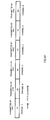
- FIG.3 shows a frame configuration example of each baseband signal.
- Spreading sections 203A, 203B obtain spread baseband signals S3A, S3B by multiplying the baseband signals by a spreading code and send these signals to radio sections 204A, 204B.
- Spreading section 203A and spreading section 203B use different spreading codes.
- Radio sections 204A, 204B form modulated signals Ta, Tb by applying radio processing such as up-conversion and amplification to spread baseband signals S3A, S3B and supply these signals to antennas AN1, AN2.
- Channel fluctuation estimation section 403-1A of modulated signal A obtains channel fluctuation estimated value h11 by estimating a channel fluctuation of modulated signal A (modulated signal Ta transmitted from antenna AN1) based on a channel estimation symbol. A channel fluctuation between antenna AN1 and antenna AN3 is estimated from this.
- Channel fluctuation estimation section 403-1B of modulated signal B obtains channel fluctuation estimated value h21 by estimating a channel fluctuation of modulated signal B (modulated signal Tb transmitted from antenna AN2) based on a channel estimation symbol. A channel fluctuation between antenna AN2 and antenna AN3 is estimated from this.
- Separation section 501 substitutes baseband signals R1-2, R2-2 and channel fluctuation estimated values h11, h21, h12, h22 into Expression (1) and performs an inverse matrix calculation of Expression (1) and thereby obtains estimated baseband signal 502 of transmission digital signal TA and estimated baseband signal 505 of transmission digital signal TB. In this way, separation section 501 performs signal separation using an inverse matrix calculation instead of carrying out a maximum likelihood detection (MLD), and can thereby perform signal separation with a smaller circuit scale compared with the case where a maximum likelihood detection is carried out. Separation section 501 sends estimated baseband signal 502 of transmission digital signal TA to soft decision section 503 and sends estimated baseband signal 505 of transmission digital signal TB to soft decision section 506.
- MLD maximum likelihood detection
- Signal point reduction section 508 estimates 16 candidate signal points 801 to 816 as shown in FIG.8 based on channel fluctuation value h12 of modulated signal A and channel fluctuation value h22 of modulated signal B. Next, signal point reduction section 508 narrows down the number of candidate signal points to 4 as shown in FIG.9 using decision value 507 of modulated signal B obtained by soft decision section 506.
- FIG.9 shows an example of candidate signal point reduction when decision value 507 of modulated signal B is (0,0), that is, 2 bits transmitted with modulated signal B are decided to be (0,0). Then, signal point reduction section 508 sends information on signal points 801, 806, 811, 816 to soft decision section 512 as signal point information 509.
- Soft decision section 512 inputs information on candidate signal points 801, 806, 811, 816 in FIG.9 as signal point information 509, 511 and inputs received baseband signals R1-2, R2-2. Soft decision section 512 makes a soft decision using candidate signal points 801, 806, 811, 816 about both of received baseband signals R1-2, R2-2.
- soft decision section 512 calculates the square of a Euclid distance between received signal point 800 and candidate signal points 801, 806, 811, 816, and thereby obtains a branch metric (this is called "Bx").
- soft decision section 518 obtains a path metric from the branch metric which is the sum of branch metric Bv and branch metric Bw and when, for example, a convolutional code is used, soft decision section 518 obtains received data RB of modulated signal B by performing decoding according to a Viterbi algorithm.
- Multi-antenna reception apparatus 120 receives two modulated signals A, B simultaneously transmitted from two antennas AN1, AN2 at two antennas AN3, AN4.
- Multi-antenna reception apparatus 120 estimates channel fluctuations between transmit antennas AN1, AN2 and receive antenna AN3, AN4 based on known signals inserted in modulated signals A, B by channel fluctuation estimation sections 403-1A, 403-1B, 403-2A, 403-2B.
- this embodiment proposes a multi-antenna reception apparatus that makes simpler the configuration of the part which makes a provisional decision to reduce candidate signal points and can thereby obtain received data with a good error rate characteristic in a simpler configuration.
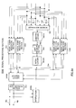
- FIG.12 which shows parts corresponding to those in FIG.5 assigned the same reference numerals shows the configuration of signal processing section 1200 of the multi-antenna reception apparatus of this embodiment.
- signal processing section 1200 in FIG.12 has a configuration without soft decision section 506 ( FIG.5 ) to decide estimated baseband signal 505 of modulated signal B separated by separation section 501.
- Received data RB of modulated signal B obtained by soft decision section 518 is input to signal point reduction sections 1201, 1202.
- Signal point reduction sections 1201, 1202 reduce candidate signal points according to a method similar to that explained in Embodiment 1 using received data RB obtained by soft decision section 518 instead of decision value 507 from soft decision section 506 ( FIG.5 ). This allows the overall circuit configuration to be simplified by the amount of space corresponding to soft decision section 506.
- Signal processing section 1200 then reduces candidate signal points about modulated signal A using data RB of modulated signal B through signal point reduction sections 1201, 1202, decodes modulated signal A through soft decision section 512 to thereby obtain received data RA of modulated signal A. In this way, instead of decoding modulated signal A and modulated signal B simultaneously, signal processing section 1200 of this embodiment decodes them alternately such as decoding modulated signal A, decoding modulated signal B, decoding modulated signal A and so on.
- this embodiment makes provisional decisions on only some modulated signals, reduces candidate signal points using a final decision result (main decision result) for other modulated signals, and can thereby realize a multi-antenna reception apparatus in a much simpler configuration in addition to the effects of Embodiment 1.
- This embodiment proposes a multi-antenna reception apparatus that not only obtains received data with a good error rate characteristic with a smaller number of calculations by making a main decision after reducing candidate signal points but also applies an iteration (repetition) technology, and can thereby further improve the error rate characteristic.
- FIG.13 which shows parts corresponding to those in FIG.5 assigned the same reference numerals shows the configuration of signal processing section 1300 of the multi-antenna reception apparatus of this embodiment. That is, signal processing section 1300 is replaced by signal processing section 404 in FIG.4 and is used for multi-antenna reception apparatus 120.
- Signal processing section 1300 of this embodiment differs from signal processing section 404 in the FIG.5 explained in Embodiment 1 in that signal point reduction sections 1301, 1302 receive received data RB from soft decision section 518 in addition to decision value 507 from soft decision section 506 and that signal point reduction sections 1303, 1304 receive received data RA from soft decision section 512 in addition to decision value 504 from soft decision section 503.
- first soft decision and decoding is the same as the operation of signal processing section 404 in FIG.5 explained in Embodiment 1. That is, signal points are reduced based on provisional decision values (decision values 504, 507) obtained by soft decision sections 503, 504. On the other hand, soft decision and decoding from the second time onward are performed using received data RA, RB obtained by soft decision sections 512, 518.
- signal point reduction sections 1301, 1302 estimate 2 bits transmitted with modulated signal B using soft decision value 507 of modulated signal B respectively, reduces 16 candidate signal points in FIG.8 to 4 signal points in FIG.9 , sends signal point information (4 signal points) 509, 511 to soft decision section 512 and soft decision section 512 obtains received data RA using signal point information 509, 511.
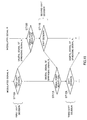
- step ST3A on modulated signal A by signal processing section 1300 signal point reduction sections 1301, 1302 estimate 2 bits transmitted with modulated signal B using received data RB obtained in step ST1B respectively, reduces 16 candidate signal points in FIG.8 to 4 signal points in FIG.9 (step ST2A), sends signal point information (4 signal points) 509, 511 to soft decision section 512 and soft decision section 512 obtains received data RA using signal point information 509, 511 (step ST3A).
- signal point reduction sections 1301, 1302 estimate 2 bits transmitted with modulated signal B using received data RB obtained in step ST3B respectively, reduces 16 candidate signal points in FIG.8 to 4 signal points in FIG.9 (step ST4A), sends signal point information (4 signal points) 509, 511 to soft decision section 512 and soft decision section 512 obtains received data RA using signal point information 509, 511 (step ST5A).
- soft decision sections 512, 518 After performing first soft decision and decoding, soft decision sections 512, 518 outputs first received data RA, RB respectively. Next, after performing second soft decision and decoding, soft decision sections 512, 518 output second received data RA, RB instead of first received data RA, RB. That is, after nth soft decision and decoding, soft decision sections 512, 518 output received data RA, RB which are nth soft decision and decoding results instead of (n-1)th received data RA, RB.
- this embodiment uses data RA, RB of the other modulated signal after error correcting decoding (after a main decision), performs iteration processing and obtains final received data RA, RB, and can thereby obtain received data RA, RB with an improved error rate characteristic compared to Embodiment 1.
- soft decision section 1705 may make a provisional decision without carrying out any inverse matrix calculation for separation of modulated signals, as shown in FIG.17 , for example.
- soft decision section 1705 obtains a branch metric from channel fluctuation signals h12, h22 of modulated signal A and despread baseband signal R2-2.
- soft decision section 1705 obtains a path metric from two branch metrics, sends decision value 1706 of modulated signal A to signal point reduction sections 1703, 1704 and sends decision value 1707 of modulated signal B to signal point reduction sections 1701, 1702.
- signal processing section 1800 corresponds to the configuration of signal processing section 1200 with iteration processing added.
- the decision value of the digital signal of modulated signal A obtained is accurate, the possibility of reducing wrong signal points becomes low when reducing signal points and the error rate characteristic of received data RB of modulated signal B obtained by soft decision section 518 improves when performing soft decision decoding on modulated signal B.
- the transmission speed it is preferable to adopt, for example, 16QAM (or 64QAM) as the modulation scheme of modulated signal B which has a greater modulation multivalue number than QPSK. This can improve both the reception quality and the transmission speed simultaneously.
- modulated signal A and modulated signal B can also obtain similar effects. For example, suppose the coding rate of modulated signal A is 1/4 and the coding rate of modulated signal B is 3/4. Then, since the reception quality of modulated signal A is better, the possibility that signal point reduction may be performed correctly increases and the reception quality of modulated signal B also improves.
- this embodiment causes the modulation scheme, coding rate, spreading factor or the like to differ from one modulated signal to another so that the reception quality varies from one modulated signal to another, and can thereby improve both the error rate characteristic and transmission speed simultaneously in addition to the effect of Embodiments 1 to 4.
- signal processing section 2400 returns an estimated baseband signal about transmission digital signal TA separated by separation section 501 to the original arrangement by deinterleaver 2401A, then sends it to soft decision section 503, and returns an estimated baseband signal about transmission digital signal TB to the original arrangement by deinterleaver 2401B, and then sends it to soft decision section 506. Furthermore, the decision value obtained by soft decision section 503 is sent to signal point reduction sections 1303, 1304 after being interleaved by interleaver 2402A and the decision value obtained by soft decision section 506 is sent to signal point reduction sections 1301, 1302 after being interleaved by interleaver 2402B.
- Examples of a method of making interleaving differ from one modulated signal to another include the following methods.
- signal processing section 3002 receives signals R1-2, R2-2 after the Fourier transform, channel fluctuation signal groups h11, h12 of modulated signal A and channel fluctuation signal groups h21, h22 of modulated signal B, decides signals R1-2, R2-2 after the Fourier transformusing channel fluctuation signal groups h11, h12, h21, h22 and thereby obtains received data RA of modulated signal A and received data RB of modulated signal B.
- This Embodiment proposes to reflect reliability in a provisional decision performed to reduce signal points in main decision processing after signal point reduction. This can further improve a data error rate characteristic obtained through the main decision processing.
- this embodiment proposes a method of weighting a branch metric of each symbol at main decision processing using the path metric value of each symbol when a soft decision is performed as a provisional decision.
- This embodiment will explain signal processing section 2400 in the configuration in FIG.24 explained in Embodiment 6 as an example. That is, a case where modulated signal A and modulated signal B interleaved in different interleaving patterns are received, separated and decoded will be explained as an example.
- this embodiment multiplies the branch metric by the value corresponding to reliability of signal point reduction, and can thereby improve reliability of the path metric. As a result, it is possible to improve the error rate characteristic of data obtained through the main decision.
- a difference between the minimum value of the path metric and the second smallest value of the path metric may also be reflected in the main decision.
- FIG.35 shows a frame configuration example of modulated signal A and modulated signal B transmitted from each antenna of the transmission apparatus.
- the transmission apparatus transmits STBC symbol 3303 regularly in addition to channel estimation symbol 3301, data symbols 3302, 3304, 3306 as modulated signal A from first antenna AN1 ( FIG.1 ).
- the transmission apparatus transmits STBC symbol 3309 regularly in addition to channel estimation symbols 3307, data symbols 3308, 3310, 3312 as modulated signal B from second antenna AN2.
- STBC symbol branch metric calculation section 4101 in signal processing section 3600 receives channel fluctuation estimated values h11, h21, h12, h22 and baseband signals R1-2, R2-2, obtains a branch metric of an STBC symbol and outputs STBC symbol branch metric signals 4102, 4103.
- Decoding section 4108 receives STBC symbol branch metric signal 4102, data symbol branch metric signal 4105, obtains a path metric, decodes it and thereby outputs decision value 504 about transmission digital signal TA. In the same way, decoding section 4109 receives STBC symbol branch metric signal 4103, data symbol branch metric signal 4107, obtains a path metric, decodes it and thereby outputs decision value 507 about transmission digital signal TB.
- the error rate characteristic of modulated signal B can be improved considerably when a path metric is obtained and soft decision decoding is performed.
- high reliability symbols (STBC symbol in FIG.40 and special symbols in FIG.44 ) of the branch metric to be inserted can also be called "pilot symbols to obtain a high reliability branch metric.”
- FIG.45(B) is divided into three portions (hereinafter, the divided blocks will be called "XB block", “YB block”, “ZB block") and at least one of the divided blocks is always transmitted from the other antenna.
- the antennas which transmit modulated signals are always switched at least once within a coded block, and therefore it is possible to change the steady state due to influences of direct waves and thereby lead to a state in which the error rate characteristic is improved.
- multi-antenna transmission apparatus 4700 inputs transmission digital signal TB to signal separation section 4712.
- Signal separation section 4712 separates transmission digital signal TB into digital signal 4713 and digital signal 4714, and sends digital signal 4713 to coding section 4715 for (Sb0,Sb2) and at the same time sends digital signal 4714 to coding section 4717 for (Sb1,Sb3).
- Coding section 4715 for (Sb0,Sb2) obtains coded bit sequence 4716 made up of coded bits Sb0, Sb2 by coding digital signal 4713 and sends this to interleaver 4719.
- Coding section 4717 for (Sb1,Sb3) obtains coded bit sequence 4718 made up of coded bits Sb1, Sb3 by coding digital signal 4714 and sends this to interleaver 4721.
- Interleavers 4708, 4710 obtain coded bit sequences 4709, 4711 by bit interleaving coded bit sequences 4705, 4707 respectively and send this to modulation section 202A.
- interleavers 4719, 4721 obtain coded bit sequences 4720, 4722 by bit interleaving coded bit sequences 4716, 4718 respectively and send this to modulation section 202B.
- deinterleaver 4914 rearranges the sequence of coded bits Sb0, Sb2 and sends coded bits Sb0, Sb2 after deinterleaving to decoding section 4915.
- Decoding section 4915 performs, for example, hard decision decoding on coded bits Sb0, Sb2 after deinterleaving and thereby outputs information 4916 on coded bits Sb0, Sb2 after error correction.
- signal point reduction sections 1301, 1302 likelihood decision section 4901, deinterleavers 4902, 4905, decoding sections 4903, 4906, information 4904, 4907 on coded bits Sa1, Sa3, Sb1, Sb3 with the improved reception quality is obtained.
- coded bit Sa0, Sa2 of modulated signal A and coded bit Sb0, Sb2 of modulated signal B are decoded (ST21A).
- signal points are reduced based on information on coded bits Sa0, Sa2, Sb0, Sb2 obtained (ST21B) and coded bits Sa1, Sa3 and coded bits Sb1, Sb3 are decoded (ST22B).
- signal points are reduced based on information on coded bits Sa1, Sa3, Sb1, Sb3 obtained (ST22A) and coded bits Sa0, Sa2 and coded bits Sb0, Sb2 are decoded (ST23A).
- similar processing will be repeated.
- the coding method can be a method of coding in the time axis direction as shown in FIG.54 or can be a method of coding in the frequency axis direction considering the horizontal axis in FIG.54 as the frequency axis.
- coding can also be performed in both the time axis and frequency axis directions.
- the reception quality can be improved by performing the above described operations a plurality of times.
- the flow chart of this processing is shown in FIG.53 .
- coded bits Sa0, Sa2 of modulated signal A and coded bits Sb0, Sb2 of modulated signal B are decoded (ST21A).
- signal points are reduced based on the information on coded bits Sa0, Sa2, Sb0, Sb2 obtained (ST21B) and coded bits Sa1, Sa3 and coded bits Sb1, Sb3 are decoded (ST22B).
- signal points are reduced based on the information on coded bits Sa1, Sa3, Sb1, Sb3 obtained (ST22A) and coded bits Sa0, Sa2 and coded bits Sb0, Sb2 are decoded (ST23A).
- similar processing will be repeated.
- FIG.59 shows an example of the reception state when pattern X (the interleaving pattern for coded bits Sa0, Sa2, Sb0, Sb2) is identical to pattern Y (the interleaving pattern for coded bits Sa1, Sa3, Sb1, Sb3).
- the coding method can be a method of coding in the time axis direction as shown in FIG.60 or coding in the frequency axis direction assuming the horizontal axis in FIG.60 as the frequency axis.
- coding can also be performed in both the time axis and frequency axis directions.
- interleaving method explained in this embodiment with drawings is only an example and the interleaving method is not limited to this. Ideally, random interleaving is suitable.
- Modulation sections 202A, 202B in FIG.23 perform modulation by assigning any one of 16 points in FIG.48(A), 48(B) according to coded bits bit-interleaved as shown above.
- the interleaving pattern of interleaver 2301A is basically made different from the interleaving pattern of interleaver 2301B as shown in FIG.23 so that the interleaving patterns differ from one modulated signal to another.
- This embodiment proposes to replace interleavers 2301A, 2301B with LDPC coders which have different generation matrices G_i (inspection matrices H_i) when LDPC is applied. This allows an effect similar to that when different interleavers are provided to be obtained so as to have different interleaving patterns.
- multi-antenna transmission apparatus 7000 receives a signal transmitted from the communication terminal in FIG.68 by antenna 7101.
- Received signal 7102 (corresponding to the modulated signal in FIG.69 ) is input to reception section 7103.
- Reception section 7103 obtains received digital signal 7104 by demodulating received signal 7102 and outputs this.
- Retransmission request detection section 7105 extracts retransmission request information 7106 from received digital signal 7104 and outputs this.
- This retransmission request information 7106 includes information on whether to retransmit modulated signal A or retransmit modulated signal B as described above.
- modulated signal of low reception field intensity is retransmitted, but when, for example, an error occurs in data 2B out of data 2A and data 2B, it is also possible to use a simple method of requesting retransmission of data 2B as another method.
- Retransmission information detection section 7304 receives channel fluctuation estimated values h11, h12, h21, h22, despread baseband signals R1-2, R2-2 and transmission method information 7302 and demodulates modulated signal A and outputs received digital signal RA of modulated signal A when transmission method information 7302 indicates a retransmission and that the retransmitted modulated signal is modulated signal A. Furthermore, when transmission method information 7302 indicates a retransmission and that the retransmitted modulated signal is modulated signal B, retransmission information detection section 7304 demodulates modulated signal B and outputs received digital signal RB of modulated signal B. This operation is performed, for example, in ⁇ 5>, ⁇ 9>, ⁇ 11> in FIG.71 .
- retransmission information detection section 7304 outputs RB (data 3B is output in the situation of ⁇ 9> in FIG.71 ), and signal processing section 7305 performs a demodulation operation using a signal point reduction using stored channel estimated values h11, h12, h21, h22, stored despread baseband signals R1-2, R2-2 and the received digital signal RB (data 3B in the situation of ⁇ 9> in FIG.71 ) of retransmitted modulated signal and outputs digital signal RA of modulated signal A (corresponds to data 3A in FIG.71 ).
- received digital signal RA of modulated signal A is input to signal point reduction sections 508, 510, 514, 516.
- signal point reduction sections 514, 516 use determined received digital signal RA of the modulated signal A to leave signal points of only modulated signal B as candidates as described in the above described embodiment and output reduced signal point information 515, 517 respectively.
- Soft decision section 518 performs soft decision decoding on modulated signal B and outputs received digital signal RB of modulated signal B.
- Data selection section 7401 selects received digital signal RB of this modulated signal B and outputs this as received digital signal 7402. At this time, signal point reduction sections 508, 510 and soft decision section 512 do not operate.
- reception quality improves significantly in a propagation environment in which the existence of direct waves is dominant.
- direct waves exist, as explained in Embodiment 10, good reception quality may not always be obtained even if reception field intensity is obtained.
- no significant improvement effect on the reception quality is obtained.
- the retransmitted modulated signal can be combined at a maximum ratio, that is, demodulated with strong field intensity, and therefore it is possible to obtain excellent quality.
- the signal which has not been retransmitted by demodulating the signal after canceling the retransmitted modulated signal from the signal in which both modulated signals are mixed (that is, stored signal), it is possible to demodulate the signal in a state of maximum ratio combining.
- a considerable improvement effect on the reception quality can be obtained even in an environment in which direct waves are dominant because both modulated signals can be demodulated in a state of maximum ratio combining.
- This embodiment has explained the case where two modulated signals A, B are transmitted at any time other than a retransmission and only one of the modulated signals is transmitted at the time of retransmission, but the point is that if the number of modulated signals to be transmitted at the time of retransmission is smaller than the number of modulated signals to be transmitted at any time other than a retransmission, the effects similar to those of the above described embodiments can be obtained.
- the terminal uses a channel estimated value obtained and stored in ⁇ 1>, baseband signal and retransmitted data 2A to cancel the modulated signal of data 2A from the stored baseband signal and demodulates data 2B from the signal after cancellation.
- the terminal uses the stored channel estimated value, baseband signal and retransmitted data 4A to cancel the modulated signal of data 4A from the stored baseband signal and demodulates data 4B from the signal after cancellation.
- This embodiment proposes a method of further improving reception quality through retransmissions by improving the method of transmitting retransmission data when adopting the retransmission method as shown in Embodiment 15 and Embodiment 16. More specifically, this embodiment applies a space-time block code or cycled delay diversity to Embodiment 15 and Embodiment 16.
- FIG.78 shows a configuration example of the multi-antenna transmission apparatus to realize this.
- multi-antenna transmission apparatus 7700 has the same configuration as that of multi-antenna transmission apparatus 7000 in FIG.70 except in that coded data S1A is also input to modulation section 202B in addition to modulation section 202A and coded data S1B is also input to modulation section 202A in addition to modulation section 202B.
- retransmission information detection section 7304 is designed to perform demodulation according to the rules of the space-time code or cycled delay diversity. Other operations are the same as those explained in Embodiment 15 and Embodiment 16.
- This embodiment proposes a multi-antenna reception apparatus and method capable of obtaining received digital data with a further improved error rate characteristic by improving the method of MLD (Maximum Likelihood Detection) carried out at soft decision sections 1101, 1705 of the signal processing section shown, for example, in FIG.11 , FIG.17 and improving the accuracy of a provisional decision.
- MLD Maximum Likelihood Detection
- candidate signal points are classified into two (a plurality of) sets and soft decision decoding is performed using a minimum square Euclid distance between the points of each set and the point of the received signal, and therefore it is possible to perform MLD with a reduction of the coding gain suppressed and improve the error rate characteristic at the time of a provisional decision. As a result, the received digital data with the further improved error rate characteristic can be obtained.
- coding sections 201A, 201B, modulation sections 202A, 202B in FIG.70 receive frame configuration signal S10, change the frame configuration based on a frame switching rule in FIG.80 and performs a retransmission.
- the base station transmits data 1A with modulated signal A and data 1B with modulated signal B in the frame configuration with no specific symbols inserted as shown in FIG.80(A) .
- the terminal receives the data without any error, it requests no retransmission as shown in ⁇ 2>.
- the base station transmits data 2A with modulated signal A and data 2B with modulated signal B in the frame configuration with specific symbols inserted as shown in FIG.80(B) which improves reception quality compared to that of the frame configuration in FIG.80(A) as shown in ⁇ 5>.
- the terminal receives this data without errors, it requests no retransmission as shown in ⁇ 6>.
- the base station transmits data 3A with modulated signal A and data 3B with modulated signal B in the frame configuration with no specific symbols inserted as shown in FIG.80(A) .
- the terminal receives this data with an error, it requests a retransmission as shown in ⁇ 8>.
- the data transmission speed decreases as the number of times specific symbols are inserted increases, but when compared to, for example, the modulation scheme is changed (using a modulation scheme whereby the amount of data transmitted with one symbol is decreased as the number of retransmissions increases), the reduction of the data transmission speed is significantly small.
- FIG.84 shows a configuration example of the reception apparatus in this case.
- the configuration example in FIG.84 corresponds to signal processing section 2400 in FIG.24 explained in Embodiment 6. What is different from FIG.24 is that it is provided with only deinterleavers 2401A, 2403A, only interleavers 2402A, 2405A and only soft decision sections 503, 512.
- interleaver 2301A of multi-antenna transmission apparatus 7900 interleaves these bits and then arranges 6 bits for each channel A, B.
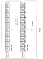
- This situation is shown in FIG.85-1 , FIG.85-2 .
- #1, #2, ⁇ , #12 show the data sequence before interleaving.
- #1 to #6 are symbols on channel A and #7 to #12 are symbols on channel B.
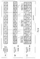
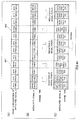
- Multi-antenna transmission apparatus 7900 applies interleaving using first 6 symbols #1 to #6 and applies interleaving using second 6 symbols #7 to #12 to input data as shown in FIG.85-1(A) . Then, the first 6 symbols are regarded as symbols on channel A and second 6 symbols are regarded as symbols on channel B.
- transmission frame configurations of channel A and channel B having different sequences are formed in the time axis direction.
- symbols A5 and B1 are transmitted from different antennas at the same time and likewise, symbols A3 and B5 are transmitted from different antennas at the same time.
- This concept can also be applied to a case where the number of channels is equal to or more than 3.
- a case where the number of transmit antennas is 3 and there are 3 transmit antennas will be explained.
- a case where block interleaving is applied to channel A for every x symbols, to channel B for every y symbols and to channel C for every z symbols is considered.
- x ⁇ y ⁇ z z and at least two values may be prime numbers. That is, when x, y are prime numbers, the block size becomes xyz which is the least common multiple thereof.
- a block interleaver for every x symbols performs interleaving in an interleaving pattern of block size xyz.
- Processing as shown in FIG.90(B), FIG.90(C), FIG.90(D) may also be realized, for example, by multi-antenna transmission apparatus 7900 in the configuration as shown in FIG.83 or may be realized by multi-antenna transmission apparatus 8400 in the configuration as shown in FIG.91.
- FIG.91 shows parts corresponding to those in FIG.83 assigned the same reference numerals.
- the difference between multi-antenna transmission apparatus 7900 in FIG.83 and multi-antenna transmission apparatus 8400 of FIG.91 is whether the interleaving processing in FIG.90(B), FIG.90(C), FIG.90(D) is performed by one interleaver 2301A or by interleavers 8401A, 8401B provided for their respective channels.
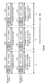
- interleaver 2301A outputs data in a sequence of B1, B11, B21, B2, B12, B22, ⁇ , B10, B20, B30 as shown in FIG.93(E) as digital signal S10B after interleaving.
- the receiving side applies deinterleaving processing as shown in FIG.94 to the signal interleaved and transmitted and performs soft decision decoding processing. Then, as explained in Embodiment 6, errors occur consecutively when a convolutional code or the like is used.
- Working Example 1 and Working Example 2 have explained the method of forming signals in interleaving patterns which differ between channels and improving reception quality when there are one coding section and one interleaver, but the interleaving pattern and the method of data arrangement are not limited to the methods in Working Example 1 and Working Example 2. Furthermore, when LDPC is applied as an error correcting code, as explained in Embodiment 14, it is also possible to realize the interleaving method whereby data on channel A is not interleaved while data on channel B is interleaved using one interleaver in the same way as in Working Example 1 and Working Example 2.
- This Working Example will explain an example of the multi-antenna transmission apparatus that makes an interleaving pattern of a modulated signal transmitted from each antenna differ from one modulated signal to another and the reception apparatus that receives and demodulates the modulated signals, explained in the embodiments so far such as Embodiment 6 and Embodiment 7, where identical data is transmitted with the respective modulated signals to improve reception quality.
- the reception apparatus of this Working Example can be configured as shown in FIG.4 , for example.
- Signal processing section 404 in FIG.4 can be configured as shown in FIG.97 .
- FIG.97 parts operating in the same way as those in FIG.24 are assigned the same reference numerals as those in FIG.24 .
- the difference in the configuration between signal processing section 9200 in FIG.97 and signal processing section 2400 in FIG.24 is that while signal processing section 2400 in FIG.24 is provided with two soft decision sections 503, 506 for a provisional decision and two soft decision sections 512, 518 for a main decision, signal processing section 9200 is provided with one soft decision sections 503 for a provisional decision and one soft decision section 512 for a main decision.
- Embodiment 6 As the method of generating different interleaving patterns, the method explained in Embodiment 6 can be applied. Furthermore, this Working Example has explained the case where the number of transmit antennas is 2 and the number 2 of receive antennas is 2 as an example, but the present invention is not limited to this and when, for example, the number of transmit antennas is 3, identical data is transmitted from three antennas but the present invention can be implemented in the same way by using different interleaving patterns,.
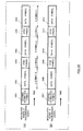
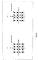
- FIG.98 56 pieces of data which composes a block are virtually assigned numbers indicating the sequence for convenience of explanation.
- FIG.98(A) shows the sequences before interleaving on channel A and channel B. However, actually, there are eight symbols without data.
- FIG.98(A) suppose no data exists in data #A2, #A5, #A9, #A13, #A44, #A48, #A52, #A55 on channel A.
- the method of transmitting modulated signals whereby an interleaving pattern is made to differ between the above described channels can also obtain effects similar to those described above when applied to an MIMO system whereby a transmission signal is converted to multi-beams and transmitted as described in, for example, a document " Eigen Beam Space Division Multiple (E-SDM) Scheme on MIMO Channel” Institute of Electronics, Information and Communication Engineers, TECHNICAL REPORT OF IEICE RCS2002-53, May, 2002 .
- E-SDM Eigen Beam Space Division Multiple
- channel analysis section 8611 calculates a plurality of reception channel signature vectors to separate the multiplexed transmission signal based on the channel condition information that is an estimation result on the propagation channel.
- Multiplexed signal separation section 8613 receives a received signal of reception array antenna 8612, multiplies the respective received signals by separate channel signature vectors and thereby separates the signal in which a plurality of transmission frames are multiplexed into a plurality of received signal frames.
- Signal processing section 8614 obtains received data by demodulating and decoding the separated received signal frames.
- signal processing section 8614 has the deinterleaving processing and signal point reduction process functions as described above. This makes it possible to obtain received data with a good error rate characteristic as shown in above described Embodiment 6 and Working Example 1 or the like.
- Embodiment 15 when the retransmission method explained in Embodiment 15 is applied to an MIMO system which performs beam forming as shown in FIG.101 , it is possible to improve signal quality in the MIMO system at the time of retransmission. That is, when carrying out a retransmission, the number of modulated signals to be transmitted is reduced compared to the previously transmitted modulated signals. For example, if beams of modulated signals A, B are formed and transmitted at the first transmission, beams are formed not from both modulated signal A, B at the time of retransmission but from only data of one of the modulated signals and retransmitted. By so doing, the number of beams decreases at the time of retransmission, and therefore it is possible to reduce interference among beams, and as a result, improve quality of the retransmission signal.
- the position of the beam at the time of retransmission may be changed from that of the last transmission. For example, if there is a retransmission request for retransmission of modulated signal B when modulated signal A is transmitted with beam 1 and modulated signal B is transmitted with beam 2 last time, modulated signal B is transmitted with beam 1 at the time of retransmission. In this way, the quality of modulated signal B can be further improved, which is preferable. That is, the fact that there has been no retransmission request for modulated signal A means that there is a high possibility that beam 1 rather than beam 2 may be the beam which allows transmission of higher quality. By sending a retransmission signal with a beam which allows transmission of higher quality at the time of retransmission in this way, the quality of the retransmission signal can be further improved.
- the multi-antenna reception apparatus further comprises a signal point reduction section that reduces candidate signal points for the subject modulated signal using digital data other than the subject modulated signal out of the digital data obtained by said main decision section.
- the multi-antenna reception apparatus further comprises a signal point reduction section that reduces the candidate signal points for the subject modulated signal using the digital data other than the subject modulated signal out of the digital data obtained by said main decision section, wherein the candidate signal points are reduced by recursively using the digital data obtained by said main decision section sequentially.
- each modulated signal is separated by an inverse matrix calculation of a channel fluctuation matrix and each modulated signal after the separation is decided for each modulated signal and in said main decision step, a calculation including a maximum likelihood detection is carried out.
- the multi-antenna transmission apparatus further comprises a space-time code insertion section that inserts space-time codes between data symbols.
- the multi-antenna transmission apparatus comprises an LDPC (Low Density Parity Check) coder instead of said interleaver, wherein signals transmitted from said respective antennas are interleaved in different interleaving patterns by changing a generation matrix of said LDPC coder.
- LDPC Low Density Parity Check
- Another aspect of the multi-antenna transmission apparatus is that said interleaver applies interleaving processing for every xth symbol to transmission signals transmitted from a first antenna out of said plurality of antennas and applies interleaving processing for every yth (x ⁇ y) symbol to transmission signals transmitted from a second antenna.
- An even further aspect of the multi-antenna transmission apparatus is that said interleaver further applies interleaving processing whereby an offset is provided in the frequency direction or in the time direction between block interleaving on the transmission signal transmitted from the first antenna and block interleaving on the transmission signal transmitted from the second antenna.
Landscapes
- Engineering & Computer Science (AREA)
- Computer Networks & Wireless Communication (AREA)
- Signal Processing (AREA)
- Power Engineering (AREA)
- Physics & Mathematics (AREA)
- Discrete Mathematics (AREA)
- General Physics & Mathematics (AREA)
- Mathematical Physics (AREA)
- Radio Transmission System (AREA)
- Detection And Prevention Of Errors In Transmission (AREA)
- Error Detection And Correction (AREA)
Priority Applications (1)
| Application Number | Priority Date | Filing Date | Title |
|---|---|---|---|
| EP16181167.4A EP3119021B1 (fr) | 2003-11-21 | 2004-11-17 | Appareil à antennes multiples avec différents modèles d'entrelacement |
Applications Claiming Priority (8)
| Application Number | Priority Date | Filing Date | Title |
|---|---|---|---|
| JP2003391860 | 2003-11-21 | ||
| JP2004003885 | 2004-01-09 | ||
| JP2004071780 | 2004-03-12 | ||
| JP2004139241 | 2004-05-07 | ||
| JP2004146887 | 2004-05-17 | ||
| JP2004180277 | 2004-06-17 | ||
| JP2004318521 | 2004-11-01 | ||
| EP04818932.8A EP1684454A4 (fr) | 2003-11-21 | 2004-11-17 | Procede, dispositif, appareil de transmission et systeme de communication multi-antenne |
Related Parent Applications (1)
| Application Number | Title | Priority Date | Filing Date |
|---|---|---|---|
| EP04818932.8A Division EP1684454A4 (fr) | 2003-11-21 | 2004-11-17 | Procede, dispositif, appareil de transmission et systeme de communication multi-antenne |
Related Child Applications (1)
| Application Number | Title | Priority Date | Filing Date |
|---|---|---|---|
| EP16181167.4A Division EP3119021B1 (fr) | 2003-11-21 | 2004-11-17 | Appareil à antennes multiples avec différents modèles d'entrelacement |
Publications (1)
| Publication Number | Publication Date |
|---|---|
| EP2690814A1 true EP2690814A1 (fr) | 2014-01-29 |
Family
ID=34624139
Family Applications (3)
| Application Number | Title | Priority Date | Filing Date |
|---|---|---|---|
| EP20130190242 Ceased EP2690814A1 (fr) | 2003-11-21 | 2004-11-17 | Appareil à antennes multiples avec différents modèles d'entrelacement |
| EP04818932.8A Withdrawn EP1684454A4 (fr) | 2003-11-21 | 2004-11-17 | Procede, dispositif, appareil de transmission et systeme de communication multi-antenne |
| EP16181167.4A Expired - Lifetime EP3119021B1 (fr) | 2003-11-21 | 2004-11-17 | Appareil à antennes multiples avec différents modèles d'entrelacement |
Family Applications After (2)
| Application Number | Title | Priority Date | Filing Date |
|---|---|---|---|
| EP04818932.8A Withdrawn EP1684454A4 (fr) | 2003-11-21 | 2004-11-17 | Procede, dispositif, appareil de transmission et systeme de communication multi-antenne |
| EP16181167.4A Expired - Lifetime EP3119021B1 (fr) | 2003-11-21 | 2004-11-17 | Appareil à antennes multiples avec différents modèles d'entrelacement |
Country Status (5)
| Country | Link |
|---|---|
| US (3) | US7864903B2 (fr) |
| EP (3) | EP2690814A1 (fr) |
| JP (2) | JP4490922B2 (fr) |
| CN (2) | CN1883145B (fr) |
| WO (1) | WO2005050885A1 (fr) |
Families Citing this family (100)
| Publication number | Priority date | Publication date | Assignee | Title |
|---|---|---|---|---|
| JP4323985B2 (ja) * | 2003-08-07 | 2009-09-02 | パナソニック株式会社 | 無線送信装置及び無線送信方法 |
| KR100714972B1 (ko) * | 2004-08-17 | 2007-05-04 | 삼성전자주식회사 | 하이브리드 자동재전송요구 시스템에서 최적의 시공간부호를 설계하기 위한 방법 |
| JP4464836B2 (ja) * | 2005-01-14 | 2010-05-19 | パナソニック株式会社 | マルチアンテナ通信装置の通信方法及びマルチアンテナ通信装置 |
| US20060251181A1 (en) * | 2005-03-22 | 2006-11-09 | Beceem Communications, Inc. | Method and system for signal detection using a reduced transmitter constellation |
| JP4212567B2 (ja) * | 2005-03-31 | 2009-01-21 | 株式会社東芝 | 受信装置および復調方法 |
| US8842693B2 (en) | 2005-05-31 | 2014-09-23 | Qualcomm Incorporated | Rank step-down for MIMO SCW design employing HARQ |
| KR100790359B1 (ko) * | 2005-06-08 | 2008-01-02 | 한국전자통신연구원 | 공간/코드블록코딩 송신 다이버시티 장치 및 그 방법, 그를 이용한 cdma다이버시티 송신기와, 그에 따른 cdma이동국 수신기 |
| US7738356B2 (en) * | 2005-06-28 | 2010-06-15 | Broadcom Corporation | Multiple stream cyclic-shifted delay transmitter |
| JP4753737B2 (ja) * | 2005-07-18 | 2011-08-24 | 三洋電機株式会社 | 無線装置 |
| WO2007021122A1 (fr) * | 2005-08-19 | 2007-02-22 | Samsung Electronics Co., Ltd. | Procede de mappage de sous-porteuse variable et son dispositif |
| JP5002215B2 (ja) | 2005-08-24 | 2012-08-15 | パナソニック株式会社 | Mimo受信装置及びmimo受信方法 |
| US7539265B2 (en) * | 2005-11-09 | 2009-05-26 | Chung Shan Institute Of Science And Technology, Armaments Bureau, M.N.D. | Multiple-input multiple-output code division multiple access (MIMO-CDMA) wireless communication equipment |
| KR100739182B1 (ko) * | 2005-12-08 | 2007-07-13 | 엘지전자 주식회사 | 시공간 harq 기법을 제공하는 이동 통신 단말기 및 그방법 |
| KR101241895B1 (ko) | 2006-04-10 | 2013-03-11 | 엘지전자 주식회사 | 다수의 반송파를 이용한 반복 전송 방법 |
| JP4912232B2 (ja) * | 2006-08-03 | 2012-04-11 | パナソニック株式会社 | マルチアンテナ受信装置 |
| WO2008016024A1 (fr) * | 2006-07-31 | 2008-02-07 | Panasonic Corporation | Dispositif récepteur à plusieurs antennes |
| JP2008035442A (ja) * | 2006-07-31 | 2008-02-14 | Matsushita Electric Ind Co Ltd | マルチアンテナ受信装置、マルチアンテナ送信装置及びマルチアンテナ通信システム |
| KR20080035424A (ko) * | 2006-10-19 | 2008-04-23 | 엘지전자 주식회사 | 데이터 전송 방법 |
| TWI323596B (en) * | 2006-12-13 | 2010-04-11 | Inst Information Industry | Channel estimation device, method, application program, and computer readable medium for estimating channel by a previous channel signal |
| US8228782B2 (en) | 2006-12-22 | 2012-07-24 | Lg Electronics Inc. | Sequence generation and transmission method based on time and frequency domain transmission unit |
| US8509710B2 (en) * | 2007-02-06 | 2013-08-13 | Qualcomm Incorporated | MIMO transmission with explicit and implicit cyclic delays |
| US8780771B2 (en) * | 2007-02-06 | 2014-07-15 | Qualcomm Incorporated | Cyclic delay diversity and precoding for wireless communication |
| JP4079197B1 (ja) * | 2007-02-06 | 2008-04-23 | 松下電器産業株式会社 | 受信装置とこれを用いた受信システム |
| US8379738B2 (en) * | 2007-03-16 | 2013-02-19 | Samsung Electronics Co., Ltd. | Methods and apparatus to improve performance and enable fast decoding of transmissions with multiple code blocks |
| KR101414611B1 (ko) * | 2007-04-19 | 2014-07-07 | 엘지전자 주식회사 | 다중 안테나 시스템에서 신호 송신 방법 |
| KR101414310B1 (ko) | 2007-06-19 | 2014-07-01 | 파나소닉 인텔렉츄얼 프로퍼티 코포레이션 오브 아메리카 | 기지국 장치, 이동국 장치, 데이터 송신 방법, 데이터 수신 방법 및 집적 회로 |
| JP5089270B2 (ja) * | 2007-06-29 | 2012-12-05 | パナソニック株式会社 | マルチアンテナ送信装置 |
| JP4871801B2 (ja) * | 2007-07-09 | 2012-02-08 | キヤノン株式会社 | 通信装置、通信方法、当該通信方法をコンピュータに実行させるためのコンピュータプログラム |
| US8386878B2 (en) * | 2007-07-12 | 2013-02-26 | Samsung Electronics Co., Ltd. | Methods and apparatus to compute CRC for multiple code blocks |
| CN103607216B (zh) * | 2007-09-12 | 2016-05-18 | 夏普株式会社 | 无线通信方法、无线通信系统和无线发送装置 |
| US20090177852A1 (en) * | 2008-01-09 | 2009-07-09 | Mediatek Inc. | Data block receiver and method for decoding data block |
| CN101483503B (zh) * | 2008-01-10 | 2013-01-16 | 华为技术有限公司 | 多输入多输出系统数据发送、接收方法及装置 |
| EP2247016A4 (fr) * | 2008-02-21 | 2011-02-23 | Sharp Kk | Dispositif de réception, dispositif d'émission, système de communication et procédé de communication |
| WO2009104574A1 (fr) * | 2008-02-21 | 2009-08-27 | シャープ株式会社 | Dispositif d'émission, dispositif de réception, système de communication et procédé de communication |
| US8345794B2 (en) * | 2008-04-29 | 2013-01-01 | Qualcomm Incorporated | Encoded control channel information interleaving |
| JP5031670B2 (ja) * | 2008-06-02 | 2012-09-19 | 株式会社日立製作所 | 送信装置、基地局及びシンボル送信方法 |
| ES2431337T3 (es) | 2008-06-04 | 2013-11-26 | Sony Corporation | Nueva estructura de trama para sistemas de múltiples portadoras |
| US8730853B2 (en) | 2008-09-05 | 2014-05-20 | Mediatek Inc. | Methods for responding to co-located coexistence (CLC) request from a mobile electronic device and communications apparatuses capable of controlling multi-radio coexistence |
| CN101771418B (zh) * | 2009-01-07 | 2014-11-05 | 华为技术有限公司 | 编码方法及其装置 |
| US10411846B1 (en) * | 2009-03-24 | 2019-09-10 | Marvell International Ltd. | Multi-radio device for WLAN |
| US8773969B1 (en) | 2009-03-24 | 2014-07-08 | Marvell International Ltd. | Multi-radio device for WLAN |
| JP5347709B2 (ja) * | 2009-05-18 | 2013-11-20 | 富士通株式会社 | 無線装置 |
| US8223896B2 (en) * | 2009-07-28 | 2012-07-17 | Telefonaktiebolaget L M Ericsson (Publ) | Soft bit value generation in a sequence estimator |
| JP5672684B2 (ja) * | 2009-09-29 | 2015-02-18 | ソニー株式会社 | 無線伝送システム、無線通信装置、無線伝送方法 |
| CN102986155B (zh) | 2010-06-17 | 2015-09-02 | 松下电器(美国)知识产权公司 | 预编码方法、发送装置 |
| WO2011158496A1 (fr) | 2010-06-17 | 2011-12-22 | パナソニック株式会社 | Procédé de précodage, et dispositif d'émission |
| JP5623248B2 (ja) | 2010-09-10 | 2014-11-12 | パナソニックインテレクチュアル プロパティ コーポレーション オブアメリカPanasonic Intellectual Property Corporation of America | 送信方法、送信装置、受信方法および受信装置 |
| EP2618509A4 (fr) | 2010-09-15 | 2017-11-01 | Fujitsu Limited | Procédé et système de communication sans fil, station de base et station mobile |
| JP5578617B2 (ja) | 2010-10-18 | 2014-08-27 | パナソニック インテレクチュアル プロパティ コーポレーション オブ アメリカ | 送信方法、送信装置、受信方法および受信装置 |
| US8953713B2 (en) | 2010-11-08 | 2015-02-10 | Qualcomm Incorporated | System and method for uplink multiple input multiple output transmission |
| US8842542B2 (en) | 2012-02-08 | 2014-09-23 | Qualcomm Incorporated | Method and apparatus for scheduling resources for uplink MIMO communication |
| US9084207B2 (en) | 2010-11-08 | 2015-07-14 | Qualcomm Incorporated | System and method for uplink multiple input multiple output transmission |
| US9007888B2 (en) | 2010-11-08 | 2015-04-14 | Qualcomm Incorporated | System and method for uplink multiple input multiple output transmission |
| US9516609B2 (en) | 2010-11-08 | 2016-12-06 | Qualcomm Incorporated | System and method for uplink multiple input multiple output transmission |
| US9380490B2 (en) | 2010-11-08 | 2016-06-28 | Qualcomm Incorporated | System and method for uplink multiple input multiple output transmission |
| US8948305B2 (en) | 2010-11-16 | 2015-02-03 | Panasonic Intellectual Property Corporation Of America | Transmission method, transmission apparatus, reception method and reception apparatus |
| CN103004121B (zh) | 2010-12-10 | 2016-01-27 | 松下电器(美国)知识产权公司 | 信号生成方法及信号生成装置 |
| JP5578619B2 (ja) | 2010-12-10 | 2014-08-27 | パナソニック インテレクチュアル プロパティ コーポレーション オブ アメリカ | 送信装置および受信装置 |
| KR102067618B1 (ko) | 2010-12-10 | 2020-01-17 | 선 페이턴트 트러스트 | 송신장치 |
| AU2016210741B2 (en) * | 2010-12-10 | 2018-06-21 | Sun Patent Trust | Precoding method, and transmitting device |
| CN107612597B (zh) | 2011-02-18 | 2021-01-05 | 太阳专利托管公司 | 信号生成方法及信号生成装置 |
| US8971439B2 (en) | 2011-02-21 | 2015-03-03 | Panasonic Intellectual Property Corporation Of America | Precoding method, precoding device |
| JP2012178727A (ja) * | 2011-02-25 | 2012-09-13 | Sharp Corp | 受信装置、送信装置、受信方法、送信方法、プログラムおよび無線通信システム |
| JP5991572B2 (ja) | 2011-02-28 | 2016-09-14 | サン パテント トラスト | 送信方法および送信装置 |
| CN106850019B (zh) | 2011-04-19 | 2021-06-01 | 太阳专利托管公司 | 发送方法及发送装置、接收方法及接收装置 |
| JP5739521B2 (ja) | 2011-04-19 | 2015-06-24 | パナソニック インテレクチュアル プロパティ コーポレーション オブアメリカPanasonic Intellectual Property Corporation of America | 信号生成方法及び信号生成装置 |
| JP5657782B2 (ja) | 2011-04-19 | 2015-01-21 | パナソニック インテレクチュアル プロパティ コーポレーション オブアメリカPanasonic Intellectual Property Corporation of America | 信号生成方法及び信号生成装置 |
| EP3232590B1 (fr) | 2011-04-19 | 2018-12-05 | Sun Patent Trust | Procédé et dispositif de communication |
| US20120300877A1 (en) | 2011-05-27 | 2012-11-29 | Yutaka Murakami | Precoding method, transmitting device, and receiving device |
| WO2012176461A1 (fr) | 2011-06-24 | 2012-12-27 | パナソニック株式会社 | Dispositif de transmission, procédé de transmission, dispositif de réception et procédé de réception |
| US9179405B2 (en) | 2011-06-24 | 2015-11-03 | Panasonic Intellectual Property Corporation Of America | Transmission device, transmission method, receiving device and receiving method |
| JP5627780B2 (ja) | 2011-06-24 | 2014-11-19 | パナソニック インテレクチュアル プロパティ コーポレーション オブアメリカPanasonic Intellectual Property Corporation of America | 送信装置、送信方法、受信装置および受信方法 |
| ES2565822T3 (es) | 2011-06-24 | 2016-04-07 | Panasonic Intellectual Property Corporation Of America | Dispositivo de transmisión, método de transmisión, dispositivo de recepción y método de recepción |
| WO2012176457A1 (fr) | 2011-06-24 | 2012-12-27 | パナソニック株式会社 | Dispositif de transmission, procédé de transmission, dispositif de réception et procédé de réception |
| EP2755339B1 (fr) | 2011-09-08 | 2017-12-27 | Sun Patent Trust | Procédé de génération de signal et appareil de génération de signal |
| JP6447911B2 (ja) | 2012-05-22 | 2019-01-09 | サン パテント トラスト | 送信方法、受信方法、送信装置及び受信装置 |
| WO2013175763A1 (fr) * | 2012-05-25 | 2013-11-28 | パナソニック株式会社 | Dispositif de communication et procédé de communication |
| WO2014087674A1 (fr) | 2012-12-07 | 2014-06-12 | パナソニック株式会社 | Procédé de génération de signal, dispositif de transmission, procédé de réception, et dispositif de réception |
| EP2930870B1 (fr) | 2012-12-07 | 2021-04-28 | Sun Patent Trust | Dispositif d'émission, procédé d'émission, dispositif de réception, procédé de réception, circuit intégré et programme |
| KR102356963B1 (ko) * | 2013-01-11 | 2022-02-08 | 선 페이턴트 트러스트 | 데이터 처리방법, 프리코딩 방법, 통신장치 |
| WO2014132469A1 (fr) * | 2013-02-27 | 2014-09-04 | 株式会社国際電気通信基礎技術研究所 | Appareil terminal, appareil radio réalisant une communication radio avec celui-ci, et système de communication radio comprenant ceux-ci |
| US9225453B2 (en) * | 2013-04-09 | 2015-12-29 | Futurewei Technologies, Inc. | Optimizing optical systems using code division multiple access and/or orthogonal frequency-division multiplexing |
| US9525444B2 (en) * | 2013-07-19 | 2016-12-20 | Analog Devices Global | Adaptive element shuffler |
| CN104348764B (zh) * | 2013-07-31 | 2017-09-19 | 国际商业机器公司 | 在数据接收链路中分配计算单元的方法和装置 |
| RU2573243C2 (ru) * | 2013-10-28 | 2016-01-20 | Общество с ограниченной ответственностью "Топкон Позишионинг Системс" | Способ и устройство для измерения текущего отношения сигнал/шум при декодировании ldpc-кодов (варианты) |
| WO2015064081A1 (fr) | 2013-10-31 | 2015-05-07 | パナソニック インテレクチュアル プロパティ コーポレーション オブ アメリカ | Procédé d'émission |
| JP2017034295A (ja) * | 2013-12-13 | 2017-02-09 | シャープ株式会社 | 基地局装置、端末装置、送信方法、および受信方法 |
| EP3104540B1 (fr) | 2014-02-07 | 2021-09-15 | Panasonic Intellectual Property Corporation of America | Dispositif d'emission, procede d'emission, dispositif de reception et procede de reception |
| JP6643626B2 (ja) | 2015-02-09 | 2020-02-12 | サン パテント トラスト | 送信装置および受信装置 |
| WO2017001025A1 (fr) * | 2015-07-02 | 2017-01-05 | Huawei Technologies Co., Ltd. | Dispositif récepteur et procédés associés |
| WO2017135799A1 (fr) * | 2016-02-05 | 2017-08-10 | Samsung Electronics Co., Ltd. | Procédé d'accès multiple, et procédé de transmission, récepteur et émetteur correspondants |
| CN107070541B (zh) * | 2016-02-05 | 2021-07-09 | 北京三星通信技术研究有限公司 | 多址接入方法及相应的发射方法、接收机和发射机 |
| CN107370702B (zh) * | 2016-05-11 | 2021-08-31 | 北京三星通信技术研究有限公司 | 一种通信系统中的信号发射、接收方法和装置 |
| JP2019149592A (ja) * | 2016-07-15 | 2019-09-05 | シャープ株式会社 | 送信装置、受信装置、通信方法、および、集積回路 |
| US10771205B2 (en) * | 2016-08-12 | 2020-09-08 | Lg Electronics Inc. | Method and device for performing communication by using non-orthogonal code multiple access scheme in wireless communication system |
| JP2019054448A (ja) | 2017-09-15 | 2019-04-04 | 東芝メモリ株式会社 | メモリシステム |
| US10999054B2 (en) * | 2018-12-21 | 2021-05-04 | Motorola Solutions, Inc. | Method for synchronizing radio frequency carrier correction of dynamic radio frequency carriers |
| WO2021075105A1 (fr) * | 2019-10-17 | 2021-04-22 | ソニー株式会社 | Dispositif de radiocommunication |
| CN112737651B (zh) | 2020-12-31 | 2022-05-10 | 展讯通信(上海)有限公司 | 用于Wi-Fi的多输入多输出接收机和电子设备 |
| CN114338326B (zh) * | 2021-12-31 | 2024-03-22 | 北方联创通信有限公司 | 一种无线通信处理方法及装置 |
Citations (3)
| Publication number | Priority date | Publication date | Assignee | Title |
|---|---|---|---|---|
| US20020036980A1 (en) * | 1999-04-15 | 2002-03-28 | Lundby Stein S. | Interleaver and deinterleaver for use in a diversity transmission communication system |
| US20030012171A1 (en) * | 2001-06-25 | 2003-01-16 | Schmidl Timothy M. | Interleaver for transmit diversity |
| WO2003096599A1 (fr) * | 2002-05-10 | 2003-11-20 | Fraunhofer-Gesellschaft zur Förderung der angewandten Forschung e.V. | Procédé de diversité et dispositif |
Family Cites Families (33)
| Publication number | Priority date | Publication date | Assignee | Title |
|---|---|---|---|---|
| US4394642A (en) * | 1981-09-21 | 1983-07-19 | Sperry Corporation | Apparatus for interleaving and de-interleaving data |
| JP3242856B2 (ja) | 1997-02-17 | 2001-12-25 | シャープ株式会社 | スペクトル直接拡散通信システム |
| JPH10233758A (ja) | 1997-02-20 | 1998-09-02 | Nippon Telegr & Teleph Corp <Ntt> | 無線通信方法および装置 |
| JP3347335B2 (ja) * | 1997-11-10 | 2002-11-20 | 株式会社エヌ・ティ・ティ・ドコモ | インタリービング方法、インタリービング装置、及びインタリーブパターン作成プログラムを記録した記録媒体 |
| JP2000349654A (ja) * | 1999-03-31 | 2000-12-15 | Matsushita Electric Ind Co Ltd | 送信装置、受信装置及び送受信方法 |
| US6985434B2 (en) * | 2000-09-01 | 2006-01-10 | Nortel Networks Limited | Adaptive time diversity and spatial diversity for OFDM |
| US20020172294A1 (en) * | 2001-04-02 | 2002-11-21 | Jung-Fu Cheng | Methods and systems for selective interleaving in retransmissions and iterative demodulation of modulated signals with different interleaving |
| JP4271903B2 (ja) | 2001-06-13 | 2009-06-03 | 株式会社エヌ・ティ・ティ・ドコモ | 移動体通信システム及び移動体通信方法 |
| US6895547B2 (en) | 2001-07-11 | 2005-05-17 | International Business Machines Corporation | Method and apparatus for low density parity check encoding of data |
| JP2003032226A (ja) | 2001-07-17 | 2003-01-31 | Matsushita Electric Ind Co Ltd | 無線通信装置および無線通信方法 |
| US7115607B2 (en) | 2001-07-25 | 2006-10-03 | Amgen Inc. | Substituted piperazinyl amides and methods of use |
| KR100703295B1 (ko) * | 2001-08-18 | 2007-04-03 | 삼성전자주식회사 | 이동통신시스템에서 안테나 어레이를 이용한 데이터 송/수신 장치 및 방법 |
| EP1303032A3 (fr) | 2001-09-04 | 2005-02-09 | Philips Intellectual Property & Standards GmbH | Dispositif de commande pour un convertisseur résonnant |
| DE60112445T2 (de) | 2001-10-10 | 2006-04-06 | Matsushita Electric Industrial Co., Ltd., Kadoma | Modifikation eines Verschachtelermusters |
| EP1303051B1 (fr) * | 2001-10-10 | 2005-04-13 | Matsushita Electric Industrial Co., Ltd. | Décorrélation des interférences de trains de données entrelacées multiples |
| US7564827B2 (en) | 2001-10-19 | 2009-07-21 | Alcatel-Lucent Usa Inc. | Adaptive hybrid retransmission method for wireless communications |
| MXPA04005171A (es) * | 2001-11-29 | 2004-08-11 | Qualcomm Inc | Metodo y aparato para determinar la tasa de probabilidad logaritmica con precodificacion. |
| US7154936B2 (en) * | 2001-12-03 | 2006-12-26 | Qualcomm, Incorporated | Iterative detection and decoding for a MIMO-OFDM system |
| US6934901B2 (en) * | 2001-12-04 | 2005-08-23 | Intel Corporation | Block interleaver method and system |
| JP3490425B2 (ja) * | 2002-03-14 | 2004-01-26 | 松下電器産業株式会社 | 受信装置及び受信方法 |
| JP3658569B2 (ja) | 2002-03-27 | 2005-06-08 | 株式会社東芝 | 信号伝送システム、送信装置及び受信装置 |
| EP1494381B1 (fr) | 2002-04-09 | 2013-06-12 | Panasonic Mobile Communications Co., Ltd. | Procede et dispositif de communication par multiplexage par repartition orthogonale de la frequence (ofdm) |
| JP3796188B2 (ja) | 2002-04-09 | 2006-07-12 | パナソニック モバイルコミュニケーションズ株式会社 | Ofdm通信方法およびofdm通信装置 |
| WO2003088537A1 (fr) * | 2002-04-12 | 2003-10-23 | Matsushita Electric Industrial Co., Ltd. | Dispositif de communication multiporteuse et procede de communication multiporteuse |
| US7684329B2 (en) | 2002-05-06 | 2010-03-23 | Qualcomm Incorporated | Method and apparatus for augmenting physical layer ARQ in a wireless data communication system |
| JP3628311B2 (ja) * | 2002-06-14 | 2005-03-09 | 株式会社東芝 | ビタビ復号装置、通信システム及びビタビ復号方法 |
| ATE400103T1 (de) * | 2002-06-24 | 2008-07-15 | Mitsubishi Electric Inf Tech | Mimo-nachrichtenübertragungsverfahren mit beschleunigter kugeldecodierung |
| US7609777B2 (en) | 2002-08-30 | 2009-10-27 | Alcatel-Lucent Usa Inc. | Maximum likelihood a posteriori probability detector |
| US7317770B2 (en) | 2003-02-28 | 2008-01-08 | Nec Laboratories America, Inc. | Near-optimal multiple-input multiple-output (MIMO) channel detection via sequential Monte Carlo |
| US7822150B2 (en) | 2003-03-15 | 2010-10-26 | Alcatel-Lucent Usa Inc. | Spherical decoder for wireless communications |
| JP4077355B2 (ja) | 2003-04-16 | 2008-04-16 | 三菱電機株式会社 | 通信装置および通信方法 |
| KR100584439B1 (ko) * | 2003-11-05 | 2006-05-26 | 삼성전자주식회사 | 다중 안테나를 사용하는 직교주파수분할다중 시스템에서간섭신호 제거 장치 및 방법 |
| JP4460412B2 (ja) * | 2003-11-26 | 2010-05-12 | パナソニック株式会社 | 受信装置及び部分ビット判定方法 |
-
2004
- 2004-11-17 EP EP20130190242 patent/EP2690814A1/fr not_active Ceased
- 2004-11-17 EP EP04818932.8A patent/EP1684454A4/fr not_active Withdrawn
- 2004-11-17 US US10/579,745 patent/US7864903B2/en active Active
- 2004-11-17 WO PCT/JP2004/017096 patent/WO2005050885A1/fr not_active Ceased
- 2004-11-17 JP JP2005515629A patent/JP4490922B2/ja not_active Expired - Lifetime
- 2004-11-17 EP EP16181167.4A patent/EP3119021B1/fr not_active Expired - Lifetime
- 2004-11-17 CN CN2004800340101A patent/CN1883145B/zh not_active Expired - Lifetime
- 2004-11-17 CN CN201010297590.0A patent/CN101969325B/zh not_active Expired - Lifetime
-
2009
- 2009-11-09 JP JP2009256436A patent/JP4879309B2/ja not_active Expired - Fee Related
-
2010
- 2010-11-01 US US12/917,248 patent/US8144799B2/en active Active
-
2012
- 2012-02-17 US US13/399,848 patent/US8724729B2/en not_active Expired - Lifetime
Patent Citations (3)
| Publication number | Priority date | Publication date | Assignee | Title |
|---|---|---|---|---|
| US20020036980A1 (en) * | 1999-04-15 | 2002-03-28 | Lundby Stein S. | Interleaver and deinterleaver for use in a diversity transmission communication system |
| US20030012171A1 (en) * | 2001-06-25 | 2003-01-16 | Schmidl Timothy M. | Interleaver for transmit diversity |
| WO2003096599A1 (fr) * | 2002-05-10 | 2003-11-20 | Fraunhofer-Gesellschaft zur Förderung der angewandten Forschung e.V. | Procédé de diversité et dispositif |
Non-Patent Citations (7)
| Title |
|---|
| "Digital Communications (third edition)", 1 January 1995, MCGRAW-HILL, Singapore, article JOHN G. PROAKIS: "Digital Communications (third edition)", pages: 468 - 470, XP055217562 * |
| "Eigen Beam Space Division Multiple (E-SDM) Scheme on MIMO Channel", TECHNICAL REPORT OF IEICE RCS2002-53, May 2002 (2002-05-01) |
| "MIMO System Analysis in Rician Fading", TECHNICAL REPORT OF IEICE RCS2003-90, July 2003 (2003-07-01), pages 1 - 6 |
| "Multiple-antenna diversity techniques for transmission over fading channels", IEEE WCNC 1999, September 1999 (1999-09-01), pages 1038 - 1042 |
| "Space-Time Block Codes from Orthogonal Design", IEEE TRANSACTIONS ON INFORMATION THEORY, vol. 45, no. 5, July 1999 (1999-07-01), pages 1456 - 1467 |
| J. HOU; P. SIEGEL; L. MILSTEIN: "Performance Analysis and Code Optimization for Low Density Parity-Check Codes on Rayleigh Fading Channels", IEEE JSAC, vol. 19, no. 5, May 2001 (2001-05-01) |
| KOBAYASHI K ET AL: "Varying interleave patterns with iterative decoding for improved performance in MIMO systems", PIMRC 2004: 15 TH IEEE INTERNATIONAL SYMPOSIUM ON PERSONAL, INDOOR AND MOBILE RADIO COMMUNICATIONS, HELD IN BARCELONA, vol. 2, 5 September 2004 (2004-09-05) - 8 September 2004 (2004-09-08), PISCATAWAY, NJ, USA, pages 1429 - 1433, XP010754063, ISBN: 978-0-7803-8523-8, DOI: 10.1109/PIMRC.2004.1373934 * |
Also Published As
| Publication number | Publication date |
|---|---|
| EP3119021A2 (fr) | 2017-01-18 |
| EP1684454A1 (fr) | 2006-07-26 |
| WO2005050885A1 (fr) | 2005-06-02 |
| CN1883145B (zh) | 2010-12-08 |
| US20110044412A1 (en) | 2011-02-24 |
| EP3119021A3 (fr) | 2017-03-22 |
| US20120147989A1 (en) | 2012-06-14 |
| JP2010035223A (ja) | 2010-02-12 |
| CN1883145A (zh) | 2006-12-20 |
| US8144799B2 (en) | 2012-03-27 |
| US8724729B2 (en) | 2014-05-13 |
| JP4879309B2 (ja) | 2012-02-22 |
| JPWO2005050885A1 (ja) | 2007-06-14 |
| US7864903B2 (en) | 2011-01-04 |
| JP4490922B2 (ja) | 2010-06-30 |
| EP3119021B1 (fr) | 2018-05-02 |
| US20070140377A1 (en) | 2007-06-21 |
| CN101969325A (zh) | 2011-02-09 |
| CN101969325B (zh) | 2014-05-07 |
| EP1684454A4 (fr) | 2013-07-03 |
Similar Documents
| Publication | Publication Date | Title |
|---|---|---|
| EP3119021B1 (fr) | Appareil à antennes multiples avec différents modèles d'entrelacement | |
| US11894928B2 (en) | Wireless communication base station apparatus, wireless communication terminal, communication method of a wireless communication base station apparatus and communication method of a wireless communication terminal | |
| KR101285901B1 (ko) | Mimo 통신 시스템에서의 증분 리던던시 송신 | |
| US8472565B2 (en) | Apparatus for processing received signal, method thereof, and method for selecting mapping rule | |
| JP5731612B2 (ja) | Mimo無線通信システムにおけるアンテナマッピングのための装置及び方法 | |
| US8625692B2 (en) | Transmission/reception apparatus and method for improving throughput in a multi-input multi-output communication system | |
| US8340226B2 (en) | Multiantenna receiving device | |
| US20070268988A1 (en) | Method and system for optimal receive diversity combining | |
| US20110320920A1 (en) | Coding apparatus, receiving apparatus, wireless communication system, puncturing pattern selecting method and program thereof | |
| JP4510870B2 (ja) | 無線通信方法及び無線通信装置 | |
| US8279963B2 (en) | Data symbol mapping for multiple-input multiple-output hybrid automatic repeat request | |
| KR101346423B1 (ko) | 다중 안테나 시스템에서 데이터 전송 방법 | |
| CN101496331A (zh) | 多天线接收装置 | |
| JP2006186991A (ja) | 適応変調を用いたパケット伝送方法 | |
| KR20100007446A (ko) | 다중안테나 시스템에서 로그우도비를 생성하는 장치 및방법 |
Legal Events
| Date | Code | Title | Description |
|---|---|---|---|
| PUAI | Public reference made under article 153(3) epc to a published international application that has entered the european phase |
Free format text: ORIGINAL CODE: 0009012 |
|
| 17P | Request for examination filed |
Effective date: 20131025 |
|
| AC | Divisional application: reference to earlier application |
Ref document number: 1684454 Country of ref document: EP Kind code of ref document: P |
|
| AK | Designated contracting states |
Kind code of ref document: A1 Designated state(s): DE FR GB |
|
| RAP1 | Party data changed (applicant data changed or rights of an application transferred) |
Owner name: PANASONIC INTELLECTUAL PROPERTY CORPORATION OF AME |
|
| 17Q | First examination report despatched |
Effective date: 20150320 |
|
| RAP1 | Party data changed (applicant data changed or rights of an application transferred) |
Owner name: INTERDIGITAL PATENT HOLDINGS, INC. |
|
| STAA | Information on the status of an ep patent application or granted ep patent |
Free format text: STATUS: THE APPLICATION HAS BEEN REFUSED |
|
| 18R | Application refused |
Effective date: 20160426 |