EP2690821A1 - Procédé et appareil de mesure de mise en mémoire tampon de paquets - Google Patents
Procédé et appareil de mesure de mise en mémoire tampon de paquets Download PDFInfo
- Publication number
- EP2690821A1 EP2690821A1 EP12185284.2A EP12185284A EP2690821A1 EP 2690821 A1 EP2690821 A1 EP 2690821A1 EP 12185284 A EP12185284 A EP 12185284A EP 2690821 A1 EP2690821 A1 EP 2690821A1
- Authority
- EP
- European Patent Office
- Prior art keywords
- packets
- switching device
- packet switching
- packet
- memory
- Prior art date
- Legal status (The legal status is an assumption and is not a legal conclusion. Google has not performed a legal analysis and makes no representation as to the accuracy of the status listed.)
- Withdrawn
Links
Images


Classifications
-
- H—ELECTRICITY
- H04—ELECTRIC COMMUNICATION TECHNIQUE
- H04L—TRANSMISSION OF DIGITAL INFORMATION, e.g. TELEGRAPHIC COMMUNICATION
- H04L43/00—Arrangements for monitoring or testing data switching networks
- H04L43/08—Monitoring or testing based on specific metrics, e.g. QoS, energy consumption or environmental parameters
-
- H—ELECTRICITY
- H04—ELECTRIC COMMUNICATION TECHNIQUE
- H04L—TRANSMISSION OF DIGITAL INFORMATION, e.g. TELEGRAPHIC COMMUNICATION
- H04L43/00—Arrangements for monitoring or testing data switching networks
- H04L43/10—Active monitoring, e.g. heartbeat, ping or trace-route
- H04L43/106—Active monitoring, e.g. heartbeat, ping or trace-route using time related information in packets, e.g. by adding timestamps
-
- H—ELECTRICITY
- H04—ELECTRIC COMMUNICATION TECHNIQUE
- H04L—TRANSMISSION OF DIGITAL INFORMATION, e.g. TELEGRAPHIC COMMUNICATION
- H04L43/00—Arrangements for monitoring or testing data switching networks
- H04L43/50—Testing arrangements
-
- H—ELECTRICITY
- H04—ELECTRIC COMMUNICATION TECHNIQUE
- H04L—TRANSMISSION OF DIGITAL INFORMATION, e.g. TELEGRAPHIC COMMUNICATION
- H04L47/00—Traffic control in data switching networks
- H04L47/10—Flow control; Congestion control
- H04L47/22—Traffic shaping
-
- H—ELECTRICITY
- H04—ELECTRIC COMMUNICATION TECHNIQUE
- H04L—TRANSMISSION OF DIGITAL INFORMATION, e.g. TELEGRAPHIC COMMUNICATION
- H04L43/00—Arrangements for monitoring or testing data switching networks
- H04L43/08—Monitoring or testing based on specific metrics, e.g. QoS, energy consumption or environmental parameters
- H04L43/0876—Network utilisation, e.g. volume of load or congestion level
- H04L43/0882—Utilisation of link capacity
Definitions
- Data communication networks may include various computers, servers, nodes, routers, switches, hubs, proxies, and other devices coupled to and configured to pass data to one another. These devices are referred to herein as "network elements," and may provide a variety of network resources on a network.
- Data is communicated through data communication networks by passing protocol data units (such as packets, cells, frames, or segments) between the network elements over communication links on the network.
- protocol data units such as packets, cells, frames, or segments
- a particular protocol data unit may be handled by multiple network elements and cross multiple communication links as it travels between its source and its destination over the network.
- Hosts such as computers, telephones, cellular telephones, Personal Digital Assistants, and other types of consumer electronics connect to and transmit/receive data over the communication network and, hence, are users of the communication services offered by the communication network.
- a packet switching device such as a data switch or a router.
- a packet switching device receives data at a particular port, and outputs the data at one or more other ports onto other links on the network.
- a typical analysis of a packet switching device will look at a number of packets forwarded, a number of packets dropped, and an average latency (a measurement of how long it takes a packet to traverse a packet switching device). The commercial practice is to provide details on forwarding rates, loss rates, and latency.
- the present invention provides the capability to directly measure the buffering capacity of a packet switching device, such as how many packets can a device hold before it starts to drop packets.
- the resulting information can be used to graphically illustrate Quality of Service (QOS) principles, validate QOS characteristics, and highlight impacts associated with QOS settings that can be made.
- QOS Quality of Service
- Packet switched networks are typically bursty with lots of merging, exiting, and crossing traffic. Variable packet rates handled by the packet switches or routers lead to variable delay among packets going from one source location to a particular destination. This variable delay among packets is known as jitter. These techniques are also very good for explaining jitter measurements -- why is the jitter level for data traversing a box (or system) at a specific value.
- the method includes transmitting a plurality of packets to a packet switching device.
- the method further includes receiving packets from the packet switching device. Additionally, the method includes determining at a particular time, based on packets transmitted to said packet switching device and packets received from said packet switching device, a number of packets being held by said packet switching device.
- Other embodiments include a computer readable medium having computer readable code thereon for providing packet buffering measurement.
- the computer readable medium includes instructions for transmitting a plurality of packets to a packet switching device.
- the computer readable medium further includes instructions for receiving packets from the packet switching device.
- the computer readable medium includes instructions for determining at a particular time, based on packets transmitted to said packet switching device and packets received from said packet switching device, a number of packets being held by said packet switching device.
- Still other embodiments include a computerized system, configured to process all the method operations disclosed herein as embodiments of the invention.
- the computerized system e.g., a test system including a traffic generator and a traffic receiver
- each of the traffic generator and traffic receiver includes a memory system, a processor, and a communications interface in an interconnection mechanism connecting these components.
- the memory system is encoded with a process that provides packet buffering measurements as explained herein that when performed (e.g. when executing) on the processor, operates as explained herein within the test system to perform all of the method embodiments and operations explained herein as embodiments of the invention.
- any computerized device that performs or is programmed to perform the processing explained herein is an embodiment of the invention.
- a computer program product is one embodiment that has a computer-readable medium including computer program logic encoded thereon that when performed in a computerized device provides associated operations providing packet buffering measurements as explained herein.
- the computer program logic when executed on at least one processor with a computing system, causes the processor to perform the operations (e.g., the methods) indicated herein as embodiments of the invention.
- Such arrangements of the invention are typically provided as software, code and/or other data structures arranged or encoded on a computer readable medium such as an optical medium (e.g., CD-ROM), floppy or hard disk or other a medium such as firmware or microcode in one or more ROM or RAM or PROM chips or as an Application Specific Integrated Circuit (ASIC) or as downloadable software images in one or more modules, shared libraries, etc.
- the software or firmware or other such configurations can be installed onto a computerized device to cause one or more processors in the computerized device to perform the techniques explained herein as embodiments of the invention.
- Software processes that operate in a collection of computerized devices, such as in a group of data communications devices or other entities can also provide the system of the invention.
- the system of the invention can be distributed between many software processes on several data communications devices, or all processes could run on a small set of dedicated computers, or on one computer alone.
- the embodiments of the invention can be embodied strictly as a software program, as software and hardware, or as hardware and/or circuitry alone, such as within a data communications device.
- the features of the invention, as explained herein, may be employed in data communications devices and/or software systems for such devices such as those manufactured by Avaya, Inc. of Basking Ridge, New Jersey.
- the presently described method and apparatus for packet buffering measurements illustrates a way to directly estimate/measure the number of packets being held in the forwarding queues of a switch or router. This is accomplished by expanding upon time-stamp information typically embedded into packet flows for latency measurement purposes. Rather than simply examining the difference in the transmit time and the receive time (standard latency measure), the time-stamp information is used to keep a running total of the number of packets in flux (being held in buffers in the packet switching device under test) at any given moment in time.
- This concept is similar to superposition theory in circuit analysis -- by adding up the combined effect of many individual elements you can create a model for the function as a whole (in this case a packet-switching function).
- the presently described method and apparatus for packet buffering measurements provides a direct measurement of critical Quality of Service parameters, rather than characterizing the symptoms associated with that Quality of Service settings.
- Packet switching devices such as routers and switches are designed with a certain amount of memory.
- the memory is typically used to buffer packets when too many packets arrive at the packet switching device and can't be sent out immediately. At a later time, the packets can be taken out of memory and transmitted.
- the amount of memory in a packet switching device has an associated cost, therefore it is important to insure that the memory is used effectively. For example, if a packet switching device has five megabytes of memory, it is important to insure that all five megabytes are capable of being used if required.
- Conventional methods for determining the performance characteristics of a packet switching device include providing a flow of packets to the device, and measuring how many packets were forwarded by the device. This technique however fails to provide information relating to how much of the memory was used to hold the received packets.
- the presently described method and apparatus for packet buffering measurements allows a user to determine at any given point in time exactly how much memory is being used by the packet switching device. Also, if packets are being dropped, a determination can be made if it is it due to memory being fully utilized, or if packets are being dropped for some other reason such as misconfigured software setting or the like. Another example occurs when Quality of Service (QoS) queues are being set up by partitioning the memory wherein a first percentage of memory is used for a high priority queue and a second percentage of the memory used for a low priority queue and there is a desire to verify how those percentages are being used.
- QoS Quality of Service
- Latency is the measurement of how long does it take between the time the packet is first received at the packet switching device and the time the packet is transmitted by the packet switching device. Latency can vary based on QoS. While measuring latency is not overly cumbersome, explaining the cause of the latency number can be difficult. If it is known how many packets a system can buffer, and how the packets are going into the buffers and coming out of the buffers is examined, then a determination can be made that the latency is a certain value, and further the reason for this latency value. By accurately measuring the buffer depth, the latency measurement can be explained. For example, determinations can be made regarding is the device getting all the memory expected, how is it being used/distributed between high priority and low priority traffic, how is data going into the device, and how is data coming out of the device.
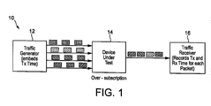
- the test system 10 includes a traffic generator 12 which provides packets to a packet switching device under test 14, and a traffic receiver 16 for receiving traffic from the packet switching device under test 14.
- the traffic generator 12 creates an oversubscription condition by sending traffic on a plurality of ports (four ports are used in this example but it should be understood that any number of ports could be used).
- the packets received by the packet switching device under test 14 are all destined for the same single port.
- Each packet transmitted by the traffic generator 12 has a transmit time embedded therein.
- the receiver 16 records the time that the packet was received as well as the transmit time of the packet. Other information may also be recorded such as the transmit port number, the QoS value (high or low priority) and the transmit port number.
- Each packet typically has a sequence number, and missing sequence numbers indicate which packets have been dropped (dropped packets are not re-transmitted).
- a timing diagram 50 is shown. On the left side of the timing diagram transmitted packets are shown, and on the rights side of the diagram received packets are shown.
- packets are transmitted on four ports.
- the packets are transmitted almost simultaneously, in order to produce an over subscription condition at the device under test (packet switching device).
- packet switching device Packet switching device
- packets sent from the second port of traffic generator to the device under test are processed by the device under test at a higher priority than traffic sent from first and fourth ports of the traffic generator and packets sent from the first port of traffic generator to the device under test are processed by the device under test at a higher priority than traffic from the fourth port of the traffic generator.
- the horizontal axis is the number of packets received.
- the vertical axis is a count of the number of packets.
- the vertical axis is a measure of latency represented in units of time.
- line 102 represents the number of packets buffered for each of the four ports. In this example, all four ports are receiving equal treatment (the same number of packets at approximately the same time), so the lines all lay directly on top of each other.
- Line 104 is the total number of buffered packets. As can be seen by line 104, the maximum number of packets is slightly over 300, and as shown in line 102, the maximum number of buffered packets for each stream is around 75 to 80 packets.
- line 106 shows the number of forwarded packets for the device. Because this is a non-QoS environment wherein each packet is treated equally, the line is linear. A little over 1,000 packets were forwarded, with a little over 250 for each of the four streams.
- Line 108 represents the measured packet loss
- dashed line 110 shows the number of buffered packets (see line 104 of Figure 3A ).
- the buffer will be drained to a low threshold (114), after which, the buffers will begin to fill again and packets are not continuously lost until the buffer reaches it's upper threshold again ((116) where this repeats, as the amount of lost packets increases until the buffer is drained to it's low threshold(118).
- Figure 3D is a graph showing the latency of the device. Latency is a measurement of how long it takes a packet to traverse the packet switching device. As packets are filling up the buffers, a high threshold is hit. These packets have to drain completely out of the buffer. Even though the buffer will start refilling at the low threshold point, the last packet received at the high threshold point will be transmitted at point 132. The time from a packet stored in a buffer at the high threshold point to zero defines the peak latency. From this graph a user can see why and when the latency hits a high point, why the line 130 has a saw-tooth shape.
- FIGS 4A through 4D four graphs are shown that relate to a QoS example device.
- the horizontal axis is the number of packets received.
- the vertical axis is a count of the number of packets.
- the vertical axis is a measure of latency represented in units of time. Here there are five streams of data at different priorities.
- a two-tiered Quality of Service implementation is represented.
- the highest priority streams (line 158 in Figure 4A ) pass through the system immediately such that no significant buffering is required; these streams require the least amount of buffering as they are held for the least amount of time.
- the second tier of service is represented by lines 150, 152, 154, and 156. Since the packet switch is oversubscribed, and these streams are treated at a lower priority, they must be held by buffers internal to the packet switch until such time that there is no high-priority traffic present. The switch buffers therefore fill up to a maximum value (represented by line 160) at which point no more packets can be held and packets start to drop.
- the highest priority streams (line 158 in Figure 4A ), have the greatest number of forwarded packets (line 170 in Figure 4B ), no lost packets in Figure 4C , and the lowest latency (line 228 in Figure 4D ).
- the second highest priority streams (lines 150 and 152 in Figure 4A ) have the second highest number of forwarded packets (lines 176 and 178 in Figure 4B ) but latency similar to the lowest priority packets which share the second-tier queue.
- the system described above also works with loss-less devices.
- the buffers will fill up.
- a message is sent to the traffic source telling it to pause its transmitter.
- packets versus packets can't be graphed, so the X axis of the resulting graph(s) becomes time.
- the resulting information can be used to determine whether a pause was sent to the transmitter at the right time.
- FIG. 5 A flow chart of a particular embodiment of the presently disclosed method 300 is depicted in Figure 5 .
- the rectangular elements are herein denoted "processing blocks" and represent computer software instructions or groups of instructions. Alternatively, the processing blocks represent steps performed by functionally equivalent circuits such as a digital signal processor circuit or an application specific integrated circuit (ASIC).
- ASIC application specific integrated circuit
- the flow diagrams do not depict the syntax of any particular programming language. Rather, the flow diagrams illustrate the functional information one of ordinary skill in the art requires to fabricate circuits or to generate computer software to perform the processing required in accordance with the present invention. It should be noted that many routine program elements, such as initialization of loops and variables and the use of temporary variables are not shown.
- Method 300 begins with processing block 302 which discloses transmitting a plurality of packets to a packet switching device.
- a packet switching device can be a data switch or a router.
- data is received on an input port and switched to one or more output ports.
- a transmit timestamp is provided for each packet transmitted.
- Processing block 306 recites receiving packets from the packet switching device.
- An over-subscription condition is reached internally by the packet switch wherein the packets are received across multiple ports faster than they can be transmitted out a fewer number of ports, resulting in the memory of the packet switching device filling up with packets.
- Processing block 308 recites recording the transmit time stamp for each packet arriving at the traffic receiver. Other information (sequence numbers, QoS levels, transmit port number, etc.) may also be recorded.
- Processing block 310 discloses determining a forwarding rate for packets through the packet switching device from the transmit timestamps, the receive timestamps, and any additional information (sequence numbers, QoS levels, transmit port number, stream numbers, etc.) associated with the incoming packets.
- the forwarding rate is based on the amount of packets that made it through the packets switching device.
- Processing block 312 states determining a number of lost packets for the packet switching device from the transmit timestamps, the receive timestamps ,and any additional information (sequence numbers, QoS levels, transmit port number, stream numbers, etc.) associated with the incoming packets.
- Lost packets are packets that were dropped by the packet switching device and appear as gaps in sequence numbers, transmitted time-stamps, or other details in the incoming streams. These lost packets can be a result of memory being exhausted, improper partitioning of memory between various QOS queues, or improper packet handling of one form or another. By examining buffer characteristics against loss characteristics it is possible to discern whether this packet loss is expected or unexpected.
- Processing block 314 recites determining a latency for packets forwarded through the packet switching device from the transmit timestamps, the receive timestamps , and any additional information (sequence numbers, QoS levels, transmit port number, stream numbers, etc.) associated with the incoming packets.
- Processing block 315 discloses providing performance results of packets buffered by the packet switching device by identifying the number of packets containing transmitted time stamps less than the current receive time stamp (of the most recently received packet) which are ultimately received at a later point in time.
- Buffer depths for the packet switch can be further characterized using additional information (sequence numbers, stream numbers, QoS levels, transmit port numbers, etc.) embedded in the received packet.
- Processing block 316 discloses providing performance results of the packet switching device to a user, the performance results including at least one of the group comprising a number of packets held by the packet switching device, a forwarding rate of the packet switching device, a packet loss rate of the packet switching device, and a latency of the packet switching device.
- Processing block 318 states the providing performance results to a user comprises providing the results in a graphical form.
- the graphs provide an easily understood and visual representation of how the packet switching device is performing, and showing different characteristics which can allow a user to change settings in order to maximize performance of the packet switching device.
- Processing continues with processing block 320 which recites determining at a particular time, based on packets transmitted to the packet switching device and packets received from the packet switching device, a number of packets being held in a memory of the packet switching device. This shows the depth of the memory (buffers) of the device.
- Processing block 322 discloses the packet switching device is used in a loss-less manner wherein when the packet switching device has a predetermined number of packets in memory a stop transmit message is sent to the traffic generator.
- the buffers will fill up.
- a message is sent to the traffic source telling it to pause its transmitter.
- packets versus packets can't be graphed, so the X-axis of the resulting graph(s) becomes time. The resulting information can be used to determine whether a pause was sent to the transmitter at the right time.
- Processing block 324 states buffering capabilities of the packet switching device are classified on a per-stream basis by associating buffer measurement details with other data embedded in the arriving packet stream.
- the other data can include, for example, sequence numbers, QoS levels, transmit port numbers and the like.
- references to "a microprocessor” and “a processor”, or “the microprocessor” and “the processor,” may be understood to include one or more microprocessors that may communicate in a stand-alone and/or a distributed environment(s), and may thus be configured to communicate via wired or wireless communications with other processors, where such one or more processor may be configured to operate on one or more processor-controlled devices that may be similar or different devices.
- Use of such "microprocessor” or “processor” terminology may thus also be understood to include a central processing unit, an arithmetic logic unit, an application-specific integrated circuit (IC), and/or a task engine, with such examples provided for illustration and not limitation.
- references to memory may include one or more processor-readable and accessible memory elements and/or components that may be internal to the processor-controlled device, external to the processor-controlled device, and/or may be accessed via a wired or wireless network using a variety of communications protocols, and unless otherwise specified, may be arranged to include a combination of external and internal memory devices, where such memory may be contiguous and/or partitioned based on the application.
- references to a database may be understood to include one or more memory associations, where such references may include commercially available database products (e.g., SQL, Informix, Oracle) and also proprietary databases, and may also include other structures for associating memory such as links, queues, graphs, trees, with such structures provided for illustration and not limitation.
- References to a network may include one or more intranets and/or the Internet, as well as a virtual network. References herein to microprocessor instructions or microprocessor-executable instructions, in accordance with the above, may be understood to include programmable hardware.
- a computer usable medium can include a readable memory device, such as a hard drive device, a CD-ROM, a DVD-ROM, or a computer diskette, having computer readable program code segments stored thereon.
- the computer readable medium can also include a communications link, either optical, wired, or wireless, having program code segments carried thereon as digital or analog signals.
Landscapes
- Engineering & Computer Science (AREA)
- Computer Networks & Wireless Communication (AREA)
- Signal Processing (AREA)
- Environmental & Geological Engineering (AREA)
- Health & Medical Sciences (AREA)
- Cardiology (AREA)
- General Health & Medical Sciences (AREA)
- Data Exchanges In Wide-Area Networks (AREA)
Applications Claiming Priority (1)
| Application Number | Priority Date | Filing Date | Title |
|---|---|---|---|
| US13/555,649 US8867350B2 (en) | 2012-07-23 | 2012-07-23 | Method and apparatus for packet buffering measurement |
Publications (1)
| Publication Number | Publication Date |
|---|---|
| EP2690821A1 true EP2690821A1 (fr) | 2014-01-29 |
Family
ID=47074602
Family Applications (1)
| Application Number | Title | Priority Date | Filing Date |
|---|---|---|---|
| EP12185284.2A Withdrawn EP2690821A1 (fr) | 2012-07-23 | 2012-09-20 | Procédé et appareil de mesure de mise en mémoire tampon de paquets |
Country Status (3)
| Country | Link |
|---|---|
| US (1) | US8867350B2 (fr) |
| EP (1) | EP2690821A1 (fr) |
| CN (1) | CN103580947A (fr) |
Cited By (1)
| Publication number | Priority date | Publication date | Assignee | Title |
|---|---|---|---|---|
| WO2019071043A1 (fr) * | 2017-10-04 | 2019-04-11 | Cisco Technology, Inc. | Signalisation de réseau d'acheminement de segment et traitement de paquets |
Families Citing this family (5)
| Publication number | Priority date | Publication date | Assignee | Title |
|---|---|---|---|---|
| EP2919424A1 (fr) * | 2014-03-10 | 2015-09-16 | Telefonaktiebolaget L M Ericsson (publ) | Numéros de séquence combiné pour support de priorité de suppression |
| US9806980B2 (en) * | 2014-03-27 | 2017-10-31 | Ixia | Methods, systems, and computer readable media for precise measurement of switching latency of packet switching devices |
| CN106487608B (zh) * | 2015-08-31 | 2019-06-07 | 华为技术服务有限公司 | 测量远端时间戳单位的方法和装置 |
| US11757751B2 (en) * | 2021-06-30 | 2023-09-12 | Juniper Networks, Inc. | Detection of network measurement inaccuracies |
| US11483229B1 (en) | 2021-06-30 | 2022-10-25 | Juniper Networks, Inc. | Detection of network measurement inaccuracies |
Citations (5)
| Publication number | Priority date | Publication date | Assignee | Title |
|---|---|---|---|---|
| WO2003023707A2 (fr) * | 2001-09-12 | 2003-03-20 | Orton Business Ltd. | Procede de calcul d'un tampon d'instabilite et d'un retard de mise en paquets |
| US20060184670A1 (en) * | 2003-08-29 | 2006-08-17 | Beeson Jesse D | System and method for analyzing the performance of multiple transportation streams of streaming media in packet-based networks |
| EP2204950A1 (fr) * | 2009-01-05 | 2010-07-07 | Alcatel, Lucent | Procédé de modélisation de la capacité tampon d'un réseau par paquets |
| EP2362589A1 (fr) * | 2010-02-22 | 2011-08-31 | Telefonaktiebolaget L M Ericsson (Publ) | Réservation de mémoire de paquet en dépéndence de la priorité et de la source et commande de débit |
| US20120039173A1 (en) * | 2010-02-16 | 2012-02-16 | Broadcom Corporation | Traffic Management In A Multi-Channel System |
Family Cites Families (7)
| Publication number | Priority date | Publication date | Assignee | Title |
|---|---|---|---|---|
| US6324165B1 (en) * | 1997-09-05 | 2001-11-27 | Nec Usa, Inc. | Large capacity, multiclass core ATM switch architecture |
| WO2002069574A1 (fr) * | 2001-02-28 | 2002-09-06 | Symmetricom, Inc. | Segmentation a liaisons multiples et reassemblage pour la liaison de circuits virtuels permanents dans un agencement de multiplexage inverse |
| US20020194343A1 (en) * | 2001-02-28 | 2002-12-19 | Kishan Shenoi | Measurement of time-delay, time-delay-variation, and cell transfer rate in ATM networks |
| US7367045B2 (en) * | 2002-03-16 | 2008-04-29 | Trustedflow Systems, Inc. | Trusted communications system |
| CN101783747B (zh) * | 2009-12-30 | 2012-06-27 | 福建星网锐捷网络有限公司 | 缓存队列长度测量方法及网络 |
| CN101800699A (zh) * | 2010-02-09 | 2010-08-11 | 上海华为技术有限公司 | 一种丢弃报文的方法及装置 |
| CN102387044A (zh) * | 2011-06-27 | 2012-03-21 | 中国商用飞机有限责任公司 | 一种对通信网络进行测试方法 |
-
2012
- 2012-07-23 US US13/555,649 patent/US8867350B2/en active Active
- 2012-09-20 EP EP12185284.2A patent/EP2690821A1/fr not_active Withdrawn
- 2012-09-28 CN CN201210394750.2A patent/CN103580947A/zh active Pending
Patent Citations (5)
| Publication number | Priority date | Publication date | Assignee | Title |
|---|---|---|---|---|
| WO2003023707A2 (fr) * | 2001-09-12 | 2003-03-20 | Orton Business Ltd. | Procede de calcul d'un tampon d'instabilite et d'un retard de mise en paquets |
| US20060184670A1 (en) * | 2003-08-29 | 2006-08-17 | Beeson Jesse D | System and method for analyzing the performance of multiple transportation streams of streaming media in packet-based networks |
| EP2204950A1 (fr) * | 2009-01-05 | 2010-07-07 | Alcatel, Lucent | Procédé de modélisation de la capacité tampon d'un réseau par paquets |
| US20120039173A1 (en) * | 2010-02-16 | 2012-02-16 | Broadcom Corporation | Traffic Management In A Multi-Channel System |
| EP2362589A1 (fr) * | 2010-02-22 | 2011-08-31 | Telefonaktiebolaget L M Ericsson (Publ) | Réservation de mémoire de paquet en dépéndence de la priorité et de la source et commande de débit |
Non-Patent Citations (2)
| Title |
|---|
| "Buffer Size Measuring Equipment for WAN", IP.COM JOURNAL, IP.COM INC., WEST HENRIETTA, NY, US, 3 September 2008 (2008-09-03), XP013126024, ISSN: 1533-0001 * |
| HONG JAMES W: "TU18: Interne Traffic Monitoring and Analysis: Methods and Applications", GLOBAL TELECOMMUNICATIONS CONFERENCE WORKSHOPS, 2004. GLOBECOM WORKSHO PS 2004. IEEE DALLAS, TX, USA 29 NOV. - 3 DEC., 2004, PISCATAWAY, NJ, USA,IEEE, 29 November 2004 (2004-11-29), pages 1 - 63, XP002609903, ISBN: 978-0-7803-8798-0 * |
Cited By (7)
| Publication number | Priority date | Publication date | Assignee | Title |
|---|---|---|---|---|
| WO2019071043A1 (fr) * | 2017-10-04 | 2019-04-11 | Cisco Technology, Inc. | Signalisation de réseau d'acheminement de segment et traitement de paquets |
| US10469367B2 (en) | 2017-10-04 | 2019-11-05 | Cisco Technology, Inc. | Segment routing network processing of packets including operations signaling and processing of packets in manners providing processing and/or memory efficiencies |
| US11388088B2 (en) | 2017-10-04 | 2022-07-12 | Cisco Technology, Inc. | Segment routing network signaling and packet processing |
| EP4027609A1 (fr) * | 2017-10-04 | 2022-07-13 | Cisco Technology, Inc. | Signalisation de réseau d'acheminement de segment et traitement de paquets |
| US11863435B2 (en) | 2017-10-04 | 2024-01-02 | Cisco Technology, Inc. | Segment routing network signaling and packet processing |
| US11924090B2 (en) | 2017-10-04 | 2024-03-05 | Cisco Technology, Inc. | Segment routing network signaling and packet processing |
| US12328255B2 (en) | 2017-10-04 | 2025-06-10 | Cisco Technology, Inc. | Segment routing network signaling and packet processing |
Also Published As
| Publication number | Publication date |
|---|---|
| US20140023069A1 (en) | 2014-01-23 |
| US8867350B2 (en) | 2014-10-21 |
| CN103580947A (zh) | 2014-02-12 |
Similar Documents
| Publication | Publication Date | Title |
|---|---|---|
| CN106850337B (zh) | 一种网络质量检测方法及装置 | |
| EP3154224B1 (fr) | Systèmes et procédés permettant de maintenir des niveaux de services de réseau | |
| US9154394B2 (en) | Dynamic latency-based rerouting | |
| CN1710888B (zh) | 生成监视数据报的方法 | |
| US8867350B2 (en) | Method and apparatus for packet buffering measurement | |
| US9847925B2 (en) | Accurate measurement of distributed counters | |
| CN102868576B (zh) | 宽带网用户接入链路下行丢包率测量方法 | |
| CN111052668A (zh) | 用于优化网络服务的驻留时间测量 | |
| CN107948103B (zh) | 一种基于预测的交换机pfc控制方法及控制系统 | |
| US20140269378A1 (en) | System And Method For Determining A Cause Of Network Congestion | |
| WO2002087276A2 (fr) | Procede et dispositif d'estimations robustes en temps reel de bande passante de goulot d'etranglement sur internet | |
| US11102273B2 (en) | Uplink performance management | |
| US20140269379A1 (en) | System And Method For Determining An Effect Of Network Congestion | |
| US9584396B2 (en) | Label-based measurement method, apparatus, and system | |
| WO2008116482A1 (fr) | Procédé et appareil pour une surveillance de performance dans un réseau de communications | |
| CN107534587B (zh) | 时延测量系统及方法 | |
| WO2014095927A1 (fr) | Sondage d'un réseau | |
| Kfoury et al. | Dynamic router's buffer sizing using passive measurements and p4 programmable switches | |
| CN114765585A (zh) | 一种服务质量检测方法、报文处理方法及装置 | |
| Ling et al. | Fullsight: Towards scalable, high-coverage, and fine-grained network telemetry | |
| CN113194007B (zh) | 一种网络可用带宽测量方法、系统、设备及可读存储介质 | |
| Irawan et al. | Performance evaluation of queue algorithms for video-on-demand application | |
| JP5923914B2 (ja) | 網状態推定装置及び網状態推定プログラム | |
| CN108347390A (zh) | 一种网络设备中流量限速的方法及装置 | |
| CN105611406A (zh) | 一种接入网服务商监测用户到视频服务器延迟特性方法 |
Legal Events
| Date | Code | Title | Description |
|---|---|---|---|
| PUAI | Public reference made under article 153(3) epc to a published international application that has entered the european phase |
Free format text: ORIGINAL CODE: 0009012 |
|
| 17P | Request for examination filed |
Effective date: 20120920 |
|
| AK | Designated contracting states |
Kind code of ref document: A1 Designated state(s): AL AT BE BG CH CY CZ DE DK EE ES FI FR GB GR HR HU IE IS IT LI LT LU LV MC MK MT NL NO PL PT RO RS SE SI SK SM TR |
|
| AX | Request for extension of the european patent |
Extension state: BA ME |
|
| RBV | Designated contracting states (corrected) |
Designated state(s): AL AT BE BG CH CY CZ DE DK EE ES FI FR GB GR HR HU IE IS IT LI LT LU LV MC MK MT NL NO PL PT RO RS SE SI SK SM TR |
|
| 17Q | First examination report despatched |
Effective date: 20160302 |
|
| STAA | Information on the status of an ep patent application or granted ep patent |
Free format text: STATUS: EXAMINATION IS IN PROGRESS |
|
| RAP1 | Party data changed (applicant data changed or rights of an application transferred) |
Owner name: EXTREME NETWORKS, INC. |
|
| STAA | Information on the status of an ep patent application or granted ep patent |
Free format text: STATUS: THE APPLICATION HAS BEEN WITHDRAWN |
|
| 18W | Application withdrawn |
Effective date: 20190211 |