EP2690909B1 - Procédé permettant d'effectuer des mesures par un équipment utilisatuer - Google Patents
Procédé permettant d'effectuer des mesures par un équipment utilisatuer Download PDFInfo
- Publication number
- EP2690909B1 EP2690909B1 EP12760851.1A EP12760851A EP2690909B1 EP 2690909 B1 EP2690909 B1 EP 2690909B1 EP 12760851 A EP12760851 A EP 12760851A EP 2690909 B1 EP2690909 B1 EP 2690909B1
- Authority
- EP
- European Patent Office
- Prior art keywords
- cell
- information
- subframe
- measurement
- signal
- Prior art date
- Legal status (The legal status is an assumption and is not a legal conclusion. Google has not performed a legal analysis and makes no representation as to the accuracy of the status listed.)
- Not-in-force
Links
- 238000005259 measurement Methods 0.000 title claims description 98
- 238000000034 method Methods 0.000 title claims description 94
- 230000004044 response Effects 0.000 claims description 33
- 238000004891 communication Methods 0.000 claims description 30
- 230000011664 signaling Effects 0.000 claims description 26
- 238000010586 diagram Methods 0.000 description 29
- 230000008569 process Effects 0.000 description 25
- 230000005540 biological transmission Effects 0.000 description 20
- 230000006870 function Effects 0.000 description 13
- 230000008054 signal transmission Effects 0.000 description 10
- 230000008859 change Effects 0.000 description 8
- 238000007726 management method Methods 0.000 description 8
- 238000013468 resource allocation Methods 0.000 description 6
- 238000005516 engineering process Methods 0.000 description 5
- 239000000470 constituent Substances 0.000 description 4
- 230000000694 effects Effects 0.000 description 3
- 230000007774 longterm Effects 0.000 description 3
- 230000002093 peripheral effect Effects 0.000 description 3
- 230000006835 compression Effects 0.000 description 2
- 238000007906 compression Methods 0.000 description 2
- 125000004122 cyclic group Chemical group 0.000 description 2
- 239000011159 matrix material Substances 0.000 description 2
- 238000010295 mobile communication Methods 0.000 description 2
- 238000012986 modification Methods 0.000 description 2
- 230000004048 modification Effects 0.000 description 2
- 238000012544 monitoring process Methods 0.000 description 2
- 230000002787 reinforcement Effects 0.000 description 2
- 241000760358 Enodes Species 0.000 description 1
- 230000004913 activation Effects 0.000 description 1
- MGSKVZWGBWPBTF-UHFFFAOYSA-N aebsf Chemical compound NCCC1=CC=C(S(F)(=O)=O)C=C1 MGSKVZWGBWPBTF-UHFFFAOYSA-N 0.000 description 1
- 238000003491 array Methods 0.000 description 1
- 230000001413 cellular effect Effects 0.000 description 1
- 230000001427 coherent effect Effects 0.000 description 1
- 230000001419 dependent effect Effects 0.000 description 1
- 238000001514 detection method Methods 0.000 description 1
- 238000001914 filtration Methods 0.000 description 1
- 238000007689 inspection Methods 0.000 description 1
- 230000002452 interceptive effect Effects 0.000 description 1
- 238000000691 measurement method Methods 0.000 description 1
- 230000001151 other effect Effects 0.000 description 1
- 238000012545 processing Methods 0.000 description 1
Images


Classifications
-
- H—ELECTRICITY
- H04—ELECTRIC COMMUNICATION TECHNIQUE
- H04W—WIRELESS COMMUNICATION NETWORKS
- H04W24/00—Supervisory, monitoring or testing arrangements
- H04W24/02—Arrangements for optimising operational condition
-
- H—ELECTRICITY
- H04—ELECTRIC COMMUNICATION TECHNIQUE
- H04W—WIRELESS COMMUNICATION NETWORKS
- H04W36/00—Hand-off or reselection arrangements
- H04W36/0005—Control or signalling for completing the hand-off
- H04W36/0083—Determination of parameters used for hand-off, e.g. generation or modification of neighbour cell lists
- H04W36/0085—Hand-off measurements
- H04W36/0088—Scheduling hand-off measurements
-
- H—ELECTRICITY
- H04—ELECTRIC COMMUNICATION TECHNIQUE
- H04J—MULTIPLEX COMMUNICATION
- H04J11/00—Orthogonal multiplex systems, e.g. using WALSH codes
- H04J11/0023—Interference mitigation or co-ordination
- H04J11/005—Interference mitigation or co-ordination of intercell interference
-
- H—ELECTRICITY
- H04—ELECTRIC COMMUNICATION TECHNIQUE
- H04W—WIRELESS COMMUNICATION NETWORKS
- H04W36/00—Hand-off or reselection arrangements
- H04W36/0005—Control or signalling for completing the hand-off
- H04W36/0055—Transmission or use of information for re-establishing the radio link
- H04W36/0072—Transmission or use of information for re-establishing the radio link of resource information of target access point
-
- H—ELECTRICITY
- H04—ELECTRIC COMMUNICATION TECHNIQUE
- H04W—WIRELESS COMMUNICATION NETWORKS
- H04W36/00—Hand-off or reselection arrangements
- H04W36/0005—Control or signalling for completing the hand-off
- H04W36/0083—Determination of parameters used for hand-off, e.g. generation or modification of neighbour cell lists
- H04W36/00837—Determination of triggering parameters for hand-off
-
- H—ELECTRICITY
- H04—ELECTRIC COMMUNICATION TECHNIQUE
- H04W—WIRELESS COMMUNICATION NETWORKS
- H04W36/00—Hand-off or reselection arrangements
- H04W36/0005—Control or signalling for completing the hand-off
- H04W36/0083—Determination of parameters used for hand-off, e.g. generation or modification of neighbour cell lists
- H04W36/0085—Hand-off measurements
- H04W36/0094—Definition of hand-off measurement parameters
-
- H—ELECTRICITY
- H04—ELECTRIC COMMUNICATION TECHNIQUE
- H04W—WIRELESS COMMUNICATION NETWORKS
- H04W36/00—Hand-off or reselection arrangements
- H04W36/24—Reselection being triggered by specific parameters
- H04W36/30—Reselection being triggered by specific parameters by measured or perceived connection quality data
-
- H—ELECTRICITY
- H04—ELECTRIC COMMUNICATION TECHNIQUE
- H04W—WIRELESS COMMUNICATION NETWORKS
- H04W36/00—Hand-off or reselection arrangements
- H04W36/0005—Control or signalling for completing the hand-off
- H04W36/0083—Determination of parameters used for hand-off, e.g. generation or modification of neighbour cell lists
- H04W36/00835—Determination of neighbour cell lists
Definitions
- the present invention relates to a wireless communication system, and more particularly, to a wireless communication system for coordinating inter-cell interference.
- a wireless communication system is a multiple access system capable of sharing available system resources (bandwidth, transmit power or the like) so as to support communication with multiple users.
- Examples of the multiple access system include a Code Division Multiple Access (CDMA) system, a Frequency Division Multiple Access (FDMA) system, a Time Division Multiple Access (TDMA) system, an Orthogonal Frequency Division Multiple Access (OFDMA) system, a Single Carrier Frequency Division Multiple Access (SC-FDMA) system, and the like.
- CDMA Code Division Multiple Access
- FDMA Frequency Division Multiple Access
- TDMA Time Division Multiple Access
- OFDMA Orthogonal Frequency Division Multiple Access
- SC-FDMA Single Carrier Frequency Division Multiple Access
- 3GPP document R2-106245 titled "Way forward for connected mode elCIC” discusses possible ABS pattern configurations of the network and its relation to UE configuration. Further, the procedural aspect of resource restriction reconfiguration is discussed.
- 3GPP document R2-111022 titled "Handling of Resource Restriction Patterns at Handover” discusses handling of resource restriction patterns in both serving cell RRM/RLM and neighbor cell RRM at handover events.
- An object of the present invention devised to solve a problem lies in a method and device for efficiently performing channel measurement, cell selection and signal transmission/reception in consideration of inter-cell interference in a wireless communication system.
- the object of the present invention can be achieved by a method of performing channel measurement at a user equipment (UE) according to claim 1 and a UE according to claim 5. Further embodiments are specified in the dependent claims.
- the present invention it is possible to efficiently perform channel measurement, cell selection and signal transmission/reception in consideration of inter-cell interference in a wireless communication system.
- CDMA Code Division Multiple Access
- FDMA Frequency Division Multiple Access
- TDMA Time Division Multiple Access
- OFDMA Orthogonal Frequency Division Multiple Access
- SC-FDMA Single Carrier Frequency Division Multiple Access
- CDMA may be implemented as radio technology such as Universal Terrestrial Radio Access (UTRA) or CDMA2000.
- TDMA may be implemented as radio technology such as Global System for Mobile communications (GSM)/General Packet Radio Service (GPRS)/Enhanced Data Rates for GSM Evolution (EDGE).
- GSM Global System for Mobile communications
- GPRS General Packet Radio Service
- EDGE Enhanced Data Rates for GSM Evolution
- OFDMA may be implemented as radio technology such as IEEE 802.11 (Wi-Fi), IEEE 802.16 (WiMAX), IEEE 802-20 or E-UTRA (Evolved UTRA).
- UTRA is part of the Universal Mobile Telecommunications System (UMTS).
- UMTS is an European based wideband code division multiple access (WCDMA), a GSM, and a 3 rd Generation (3G) asynchronous mobile communication system operating in a GPRS.
- WCDMA wideband code division multiple access
- GSM Global System for Mobile Communications
- 3G 3 rd Generation
- a 3 rd Generation Partnership Project Long Term Evolution (3GPP LTE) communication system is part of the E-UMTS (Evolved UMTS) which employs the E-UTRA, which employs OFDMA in downlink, and employs SC-FDMA in uplink.
- LTE-A LTE-Advanced
- LTE-A is an evolved version of the 3GPP LTE.
- FIG. 1 is a diagram showing a network structure of an E-UMTS.
- the E-UMTS is also referred to as a Long Term Evolution (LTE) system.
- Communication networks are widely distributed to provide various communication services such as voice and packet data services.
- the E-UMTS network mainly includes an Evolved UMTS Terrestrial Radio Access Network (E-UTRAN), an Evolved Packet Core (EPC) and one or more User Equipments (UEs).
- the E-UTRAN includes one or more base stations (eNBs) 20 and a plurality of UEs 10 may be located per cell.
- eNBs base stations
- MME/SAE gateway 30 may be located at the end of the network to be connected to an external network.
- downlink refers to communication from the eNB 20 to the UE 10 and "uplink” refers to communication from the UE to the eNB.
- the UE 10 is a portable communication device of a user and may be also referred to as a mobile station (MS), a user terminal (UT), a subscriber station (SS) or a wireless device.
- MS mobile station
- UT user terminal
- SS subscriber station
- the eNB 20 provides the UE 10 with an end point of a user plane and a control plane.
- the MME/SAE gateway 30 provides the UE 10 with an end point of a session and mobility management function.
- the eNB 20 and the MME/SAE gateway 30 may be connected via an S1 interface.
- the eNB 20 is generally a fixed station communicating with the UE 10 and may also be referred to as a base station (BS) or an access point.
- BS base station
- One eNB 20 may be located per cell.
- An interface for transmitting user traffic or control traffic may be used between eNBs 20.
- the MME performs various functions such as NAS signaling to the eNB 20, NAS signaling security, AS security control, inter CN node signaling for mobility between 3GPP access networks, idle mode UE reachability (including control and execution of paging retransmission), tracking area list management (for a UE in an idle mode and an active mode), PDN GW and serving GW selection, MME selection for handover accompanied with MME change, SGSN selection for handover to a 2G or 3G 3GPP access network, bearer management including roaming, authentication and dedicated bearer configuration, and PWS (including ETWS and CMAS) message transmission support.
- NAS signaling to the eNB 20 NAS signaling security
- AS security control for inter CN node signaling for mobility between 3GPP access networks
- idle mode UE reachability including control and execution of paging retransmission
- tracking area list management for a UE in an idle mode and an active mode
- PDN GW and serving GW selection for handover accompanied with MME change
- An SAE gateway host provides various functions such as per-user based packet filtering (e.g., using deep packet inspection), lawful interception, UE IP address allocation, transport port level packet marking in downlink, UL and DL service level charging, gating and rate reinforcement, DL rate reinforcement based on APN-AMBR.
- the MME/SAE gateway 30 is simply referred to as a "gateway" in the present specification, for clarity.
- the MME/SAE gateway 30 includes both an MME gateway and an SAE gateway.
- a plurality of nodes may be connected between the eNB 20 and the gateway 30 via an S1 interface.
- the eNBs 20 may be connected to each other via an X2 interface and neighbor eNBs may have a mesh network structure having an X2 interface.
- FIGs. 2a to 2b are diagrams showing a user-plane protocol and a control-plane protocol for an E-UTMS.
- protocol layers may be divided into a first layer L1, a second layer L2 and a third layer L3 based on the three low-level layers of the Open Systems Interconnection (OSI) model of a communication system.
- OSI Open Systems Interconnection
- a physical layer that is, the first layer L1 provides an information transport service to a higher layer using a physical channel.
- the physical layer is connected to a medium access control (MAC) layer located on a higher layer via a transport channel.
- MAC medium access control
- Data is transported between the MAC layer and the physical layer via the transport channel.
- Data is also transported between different physical layers, such as a physical layer of a transmitting side and a physical layer of a receiving side, via a physical channel.
- the MAC layer of the second layer L2 provides a service to a radio link control (RLC) layer of a higher layer via a logical channel.
- the RLC layer of the second layer L2 supports reliable data transmission. Although the RLC layer is shown in FIGs. 2a and 2b , it is noted that the RLC layer is not required if the MAC layer performs an RLC function.
- a packet data convergence protocol (PDCP) layer of the second layer performs a header compression function to reduce unnecessary control information, for efficient transmission of an Internet Protocol (IP) packet such as an IPv4 packet or an IPv6 packet in a radio interface having a relatively small bandwidth.
- IP Internet Protocol
- a radio resource control (RRC) layer located at the bottom of a third layer L3 is defined only in the control plane and is responsible for control of logical, transport, and physical channels in association with configuration, re-configuration, and release of radio bearers (RBs).
- the RB is a service that the second layer L2 provides for data communication between the UE 10 and the E-UTRAN.
- the RLC and MAC layers are terminated at the eNB 20 on the network side and may perform functions such as scheduling, automatic repeat request (ARQ) and hybrid automatic repeat request (HARQ).
- the PDCP layer is terminated at the eNB 20 on the network side and may perform user plane functions such as header compression, integrity protection and encryption.
- the RLC and MAC layers are terminated at the eNB 20 on the network side and perform the same functions as the control plane.
- the RRC layer is terminated at the eNB 20 on the network side and may perform functions such as broadcasting, paging, RRC connection management, radio bearer (RB) control, mobility functions and UE 10 measurement report and control.
- the NAS control protocol is terminated at the MME of the gateway 30 on the network side and may perform functions such as SAE bearer management, authentication, LTE_IDLE mobility handling, LTE-IDLE paging origination and security control for signaling between the gateway and the UE 10.
- the RRC state may be divided into two different states, namely, RRC_IDLE and RRC_CONNECTED.
- the UE 10 may receive a broadcast of system information and paging information during discontinuous reception (DRX) configured by non-access stratum (NAS).
- DRX discontinuous reception
- NAS non-access stratum
- the UE may be allocated an ID for uniquely identifying the UE in a tracking region, and perform public land mobile network (PLMN) selection and cell re-selection.
- PLMN public land mobile network
- no RRC context is stored in the eNB.
- the UE In the RRC_CONNECTED state, the UE has context in the E-UTRAN and E-UTRAN RRC connection and thus transmits and/or receives data to/from the eNB using the context.
- the UE 10 may report channel quality information and feedback information to the eNB.
- the E-UTRAN recognizes a cell to which the UE 10 belongs. Accordingly, the network may transmit and/or receive data to/from the UE 10, control UE mobility (e.g., handover, inter-radio access technology (RAT) cell change order to a GSM EDGE radio access network (GERAN) having network assisted cell change (NACC)), and perform cell measurement of peripheral cells.
- control UE mobility e.g., handover, inter-radio access technology (RAT) cell change order to a GSM EDGE radio access network (GERAN) having network assisted cell change (NACC)
- RAT inter-radio access technology
- GERAN GSM EDGE radio access network
- NACC network assisted cell change
- the UE 10 specifies a paging DRX cycle. More specifically, the UE 10 monitors a paging signal in a specific paging occasion per UE-specific paging DRX cycle.
- a UE receives information from an eNB in downlink (DL) and transmits information to an eNB in uplink (UL).
- Information transmitted and received between an eNB and a UE includes data and a variety of control information and various physical channels exist according to the kind/usage of information transmitted or received by the UE.
- FIG. 3 is a diagram showing physical channels used in a 3 rd Generation Partnership Project (3GPP) Long Term Evolution (LTE) system and a general signal transmission method using the same.
- 3GPP 3 rd Generation Partnership Project
- LTE Long Term Evolution
- a UE performs an initial cell search operation such as synchronization with an eNB in step S101, when power is turned on or the UE enters a new cell.
- the UE may receive a Primary Synchronization Channel (P-SCH) and a Secondary Synchronization Channel (S-SCH) from the eNB, perform synchronization with the eNB, and acquire information such as a cell ID. Thereafter, the UE may receive a physical broadcast channel (PBCH) from the eNB so as to acquire broadcast information within the cell (e.g., a master information block (MIB)). Meanwhile, the UE may receive a Downlink Reference Signal (DL RS) so as to confirm a downlink channel state in the initial cell search step.
- PBCH physical broadcast channel
- MIB master information block
- the UE which has completed the initial cell search may receive a Physical Downlink Control Channel (PDCCH) and a Physical Downlink Shared Channel (PDSCH) according to information about the PDCCH so as to acquire more detailed system information, in step S102.
- PDCH Physical Downlink Control Channel
- PDSCH Physical Downlink Shared Channel
- the UE may perform a Random Access Procedure (RACH) in steps S103 to S106, for connection to the eNB.
- RACH Random Access Procedure
- the UE may transmit a preamble through a Physical Random Access Channel (PRACH) (S103), and receive a response message to the preamble through the PDCCH and the PDSCH corresponding thereto (S104).
- PRACH Physical Random Access Channel
- S105 transmission of an additional PRACH
- reception of the PDCCH and the PDSCH corresponding thereto (S106) may be performed.
- the UE which has performed the above procedures may perform PDCCH/PDSCH reception (S107) and Physical Uplink Shared Channel PUSCH)/Physical Uplink Control Channel (PUCCH) transmission (S108) as a general uplink/downlink signal transmission procedure.
- Control information transmitted from the UE to the eNB is collectively referred to as uplink control information (UCI).
- UCI includes hybrid automatic repeat and request acknowledgement (ACK)/negative-ACK (NACK), scheduling request (SR), channel state information (CSI), etc.
- the CSI includes a channel quality indicator (CQI), a precoding matrix index (PMI), a rank indicator (RI), etc.
- the UCI may be generally transmitted via a PUCCH. However, if control information and traffic data are simultaneously transmitted, the UCI may be transmitted via a PUSCH. In addition, the UCI may be aperiodically transmitted via a PUSCH according to a network request/instruction.
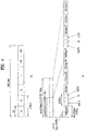
- FIG. 4 is a diagram showing the structure of a radio frame.
- uplink/downlink data packet transmission is performed in subframe units and one subframe is defined as a predetermined time interval including a plurality of OFDM symbols.
- the 3GPP LTE standard supports a type 1 radio frame structure applicable to frequency division duplex (FDD) and a type 2 radio frame structure applicable to time division duplex (TDD).
- FDD frequency division duplex
- TDD time division duplex
- FIG. 4(a) shows the structure of type 1 radio frame.
- a downlink radio frame includes 10 subframes and one subframe includes two slots in a time domain.
- a time required to transmit one subframe is referred to as a transmission time interval (TTI).
- TTI transmission time interval
- the length of one subframe may be 1 ms and the length of one slot may be 0.5 ms.
- One slot includes a plurality of OFDM symbols in a time domain and includes a plurality of resource blocks (RBs) in a frequency domain.
- RBs resource blocks
- an OFDM symbol indicates one symbol interval.
- the OFDM symbol may be referred to as an SC-FDMA symbol or symbol interval.
- a resource block (RB) as a resource allocation unit may include a plurality of consecutive subfcarriers in one slot.
- the number of OFDM symbols included in one slot may be changed according to the configuration of a Cyclic Prefix (CP).
- the CP includes an extended CP and a normal CP. For example, if the OFDM symbols are configured by the normal CP, the number of OFDM symbols included in one slot may be seven. If the OFDM symbols are configured by the extended CP, the length of one OFDM symbol is increased, the number of OFDM symbols included in one slot is less than that of the normal CP. In case of the extended CP, for example, the number of OFDM symbols included in one slot may be six. If a channel state is unstable, for example, if a user equipment (UE) moves at a high speed, the extended CP may be used in order to further reduce inter-symbol interference.
- UE user equipment
- one subframe includes 14 OFDM symbols.
- the first at most three OFDM symbols of each subframe may be allocated to a Physical Downlink Control Channel (PDCCH) and the remaining OFDM symbols may be allocated to a Physical Downlink Shared Channel (PDSCH).
- PDCCH Physical Downlink Control Channel
- PDSCH Physical Downlink Shared Channel
- FIG. 4(b) is a diagram showing the structure of the type 2 radio frame.
- the type 2 radio frame includes two half frames. Each half frame includes five subframes, a downlink pilot time slot (DwPTS), a guard period (GP), and an uplink pilot time slot (UpPTS). One subframe includes two slots.
- the DwPTS is used for initial cell search, synchronization and channel estimation at a UE.
- the UpPTS is used for channel estimation at an eNB and uplink transmission synchronization of a UE.
- the guard period is used to remove interference occurring in uplink due to multi-path delay of a downlink signal between uplink and downlink.
- the structure of the radio frame is only exemplary. Accordingly, the number of subframes included in the radio frame, the number of slots included in the subframe or the number of symbols included in the slot may be changed in various manners.
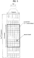
- FIG. 5 is a diagram showing a resource grid of a downlink slot.
- a downlink slot includes a plurality of OFDM symbols in a time domain.
- One downlink slot may include seven (six) OFDM symbols and one RB may include 12 subcarriers in a frequency domain.
- Each element on the resource grid is referred to as a resource element (RE).
- One RB includes 12x7(6) REs.
- the number N RB of RBs included in a downlink slot depends on a downlink transmission bandwidth.
- the structure of the uplink slot may be equal to the structure of the downlink slot, except that an OFDM symbol is replaced with an SC-FDMA symbol.
- FIG. 6 is a diagram showing the structure of a downlink subframe.
- a maximum of three (four) OFDM symbols of a front portion of a first slot within one subframe corresponds to a control region to which a control channel is allocated.
- the remaining OFDM symbols correspond to a data region to which a Physical Downlink Shared Channel (PDSCH) is allocated.
- Examples of the downlink control channels used in LTE include, for example, a Physical Control Format Indicator Channel (PCFICH), a Physical Downlink Control Channel (PDCCH), a Physical Hybrid automatic repeat request Indicator Channel (PHICH), etc.
- the PCFICH is transmitted at a first OFDM symbol of a subframe, and carries information about the number of OFDM symbols used to transmit the control channel within the subframe.
- the PHICH carries a HARQ ACK/NACK signal in response to uplink transmission.
- the control information transmitted through the PDCCH is referred to as Downlink Control Information (DCI).
- DCI includes resource allocation information and other control information for a UE or a UE group.
- the DCI includes uplink or downlink scheduling information, an uplink transmit (Tx) power control command, etc.
- the PDCCH may carry transmission format and resource allocation information of a Downlink Shared Channel (DL-SCH), transmission format and resource allocation information of an Uplink Shared Channel (UL-SCH), paging information on a Paging Channel (PCH), system information on the DL-SCH, resource allocation of a higher layer control message such as a Random Access Response (RAR) transmitted on the PDSCH, a set of transmit (Tx) power control commands for individual UEs within a UE group, a Tx power control command, information indicating activation of Voice over IP (VoIP), etc.
- a plurality of PDCCHs may be transmitted within the control region. The UE may monitor the plurality of PDCCHs.
- the PDCCHs are transmitted as an aggregate of one or several consecutive control channel elements (CCEs).
- the CCE is a logical allocation unit used to provide the PDCCHs with a coding rate based on the state of a radio channel.
- the CCE corresponds to a plurality of resource element groups (REGs).
- the format of the PDCCH and the number of PDCCH bits are determined based on the number of CCEs.
- the eNB determines a PDCCH format according to a DCI to be transmitted to the UE, and attaches a Cyclic Redundancy Check (CRC) to control information.
- the CRC is masked with a Radio Network Temporary Identifier (RNTI) according to an owner or usage of the PDCCH.
- RNTI Radio Network Temporary Identifier
- a cell-RNTI (C-RNTI) of the UE may be masked to the CRC.
- a paging indicator identifier P-RNTI
- SIB system information block
- SI-RNTI system information RNTI
- RA-RNTI random access-RNTI
- FIG. 7 is a diagram showing the structure of an uplink subframe used in LTE.
- the uplink subframe includes a plurality (e.g., 2) of slots.
- the slot may include SC-FDMA symbols, the number of which is changed according to CP length.
- the uplink subframe may be divided into a control region and a data region in a frequency domain.
- the data region includes a PUSCH and is used to transmit a data signal such as voice.
- the control region includes a PUCCH and is used to transmit uplink control information (UCI).
- the PUCCH includes an RB pair located at both ends of the data region on a frequency axis and is hopped at a slot boundary.
- the PUCCH may be used to transmit the following control information.
- the amount of control information (UCI) transmittable by a UE in a subframe depends on the number of SC-FDMA symbols available in control information transmission.
- the SC-FDMA symbols available in control information transmission mean SC-FDMA symbols excluding SC-FDMA symbols for reference signal transmission in a subframe, and a last SC-FDMA symbol of the subframe is also excluded in case of a subframe in which a sounding reference signal (SRS) is set.
- SRS sounding reference signal
- a reference signal is used for coherent detection of a PUCCH.
- the PUCCH supports 7 formats according to transmitted information.
- FIG. 8 shows an example of paging channel transmission used for an E-UMTS.
- a UE may perform discontinuous reception (DRX) for the purpose of reducing power consumption.
- a network may configure a plurality of paging occasions per time cycle which is referred to as a paging DRX cycle and a specific UE may perceive a specific paging occasion and acquire a paging message. More specifically, the UE awakes at a paging occasion and receives a PDCCH.
- P-RNTI paging-RNTI
- the UE receives an actual paging message via radio resources indicated by the PDCCH.
- the UE confirms whether an ID (e.g., an international mobile subscriber identity (IMSI)) thereof is present in the paging message and informs a higher layer that the paging has arrived if the ID is present.
- IMSI international mobile subscriber identity
- FIG. 9 is a diagram showing a cell selection/reselection process.
- the cell is selected for the purpose of registering a UE with a network to receive a service from an eNB.
- the UE should receive all system information before accessing the eNB and always have newest system information.
- the UE selects a cell in order to receive system information in an idle mode (e.g., an RRC_IDLE state), when power is first turned on. If strength or quality of a signal between the UE and the eNB is deteriorated due to mobility of the UE, the UE reselects another cell for the purpose of maintaining data transmission quality.
- an idle mode e.g., an RRC_IDLE state
- the UE when power is turned on, the UE automatically or manually selects a public land mobile network (PLMN), from which the UE receives a service, and a radio access technology (RAT) for communication (S902).
- PLMN public land mobile network
- RAT radio access technology
- the PLMN and RAT information may be selected by the user of the UE or may be stored in a universal subscriber identity module (USIM) in advance.
- USIM universal subscriber identity module
- the UE measures a signal from the eNB in all searchable frequency bands (S906) and performs an initial cell selection process of selecting a cell having a largest value among cells having the measured signal strength or quality greater than a reference value (S904).
- the reference value is defined in a system in order to guarantee the quality of a physical signal in data transmission and reception.
- the UE receives system information (SI) periodically transmitted from the serving cell.
- SI system information
- the system information includes fundamental and essential information for enabling the UE to access the network.
- the system information may include information about neighbor cells (neighbor cell list (NCL)) located adjacent to the serving cell.
- NCL neighbor cell list
- the UE waits in the idle mode (e.g., an RRC_IDLE state) in order to request a service from the network (e.g., originating call) or receive a service from the network (e.g., terminating call).
- the network registration process includes registering the ID (IMSI) of the UE in order to receive a service (e.g., page) from the network.
- the UE in the idle mode may receive control information such as system information from the cell but is not in the RRC_CONNECTED state with the UTRAN. Accordingly, since the network cannot know information about the UE, the IMSI used on non-access stratum (NAS) is used. Whenever the UE selects the cell, the UE does not register with the network. If network information included in the system information (e.g., tracking area identity (TAI) is different from the network information that the UE knows, the UE registers with the network.
- TAI tracking area identity
- the UE selects one of other peripheral cells for providing a signal property better than that of a cell of an eNB, to which the UE is connected (S912), if the signal strength or quality of the serving cell is lower than that of a neighbor cell.
- This process is referred to as cell re-selection to be distinguished from initial cell selection of S904.
- the UE in the idle mode repeats a process of re-selecting a cell having a better signal property through signal measurement of a cell, from which a service is received, and a neighbor cell.
- FIG. 10 is a diagram showing a conventional handover process.
- a UE 10 transmits a measurement report to a source eNB 20 (S602).
- the source eNB 20 transmits UE 10 context information and a handover request message to a target eNB (S1004).
- the target eNB 20 transmits a handover request response to the source eNB (S1006).
- the handover request response includes information related to random access, such as a new C-RNTI, a part of a handover command message and a dedicated random access signature for contention-free random access in a target cell.
- the source eNB 20 transmits a handover command to the UE (S1008).
- the handover command includes information related to random access such as a new C-RNTI and a dedicated signature to be used by the UE 10.
- the handover command may be indicated transmission of an RRC connection reconfiguration message having mobility control information (MCI).
- MCI mobility control information
- the UE 10 After a handover command has been received, the UE 10 performs a random access procedure with the target eNB in order to acquire a timing advance (TA) value.
- the random access procedure is a contention-free method in which a signature is reserved for the UE 10 in order to avoid collision. More specifically, the UE 10 transmits a random access preamble using a dedicated random access signature to begin the random access procedure for the target eNB 20 (S1010).
- the target eNB 20 transmits a random access response message to the UE 10 (S1012).
- the random access response message includes TA and uplink resource allocation.
- the UE 10 transmits a handover complete message to the target eNB 20 (S1014).
- FIG. 11 is a diagram showing a heterogeneous network (HetNet) having a macro cell and a micro cell.
- HetNet heterogeneous network
- next-generation communication standards including LTE-A a heterogeneous network in which a micro cell having low transmit power overlaps with existing macro cell coverage is being discussed.
- the macro cell may overlap with one or more micro cells.
- a service of the macro cell is provided by a macro eNB (macro eNode B or MeNB).
- macro cell and macro eNB may be used interchangeably.
- a UE connected to the macro cell may be referred to as a macro UE (MUE).
- MUE macro UE
- the macro UE receives a signal from the macro eNB and transmits a signal to the macro eNB.
- the micro cell is also referred to as a femto cell or a pico cell.
- a service of the micro cell is provided by a pico eNodeB, a femto eNodeB, home eNodeB (HeNB), a relay node (RN), etc.
- a pico eNodeB a pico eNodeB
- a femto eNodeB home eNodeB
- RN relay node
- micro eNodeB, micro cell, pico eNodeB, pico cell, femto eNodeB, femto cell, home eNodeB, home cell, RN and relay cell are used interchangeably, unless stated otherwise.
- the UE connected to the micro cell may be referred to as a micro UE, a pico UE (PUE), a femto UE (FUE), a home UE (HUE), etc.
- the micro UE receives a signal from the micro eNodeB (e.g., the femto eNodeB or the pico eNodeB) and transmits a signal to the micro eNodeB.
- the micro eNodeB e.g., the femto eNodeB or the pico eNodeB
- a downlink signal of the home eNodeB causes interference with respect to the macro UE.
- a downlink signal of the macro eNB may cause interference with respect to the home UE within the micro cell.
- an uplink signal of the macro UE may cause interference with respect to the home eNodeB.
- an uplink signal of the home UE may cause interference with respect to the macro eNodeB.
- the macro cell may cause strong interference with respect to the UE of the micro cell and, more particularly, the micro UE located at the boundary of the micro cell. Accordingly, a method of cancelling uplink and downlink interference for a data and L1/L2 control signal, a synchronization signal and a reference signal is required.
- An inter-cell interference cancellation (ICIC) method may be performed in a time, frequency and/or space domain.
- FIGs. 12 to 13 are diagrams showing a method of cancelling inter-cell interference in a heterogeneous network.
- an object to be protected from inter-cell interference is a pico UE.
- an aggressor which causes interference is a macro cell (or a macro eNB).
- an aggressor cell uses a time domain interference cancellation method. This example is applicable to inter-cell interference cancellation in a macro-femto scenario and a macro-macro scenario as well as a macro-pico scenario.
- the macro cell which causes inter-cell interference may allocate an almost blank subframe (ABS) (or ABSF) within a radio frame.
- ABS indicates a subframe SubF in which a normal DL signal except for a specific DL signal is not transmitted (or DL signal transmission/power is restricted or DL interference is restricted).
- the ABS may be repeated with a predetermined pattern within one or more radio frames (e.g., four radio frames). This example shows the case in which the ABS is set in subframe #2/#6.
- the macro cell may inform the micro cell of an ABS configuration (e.g., an ABS allocation pattern) via backhaul and the micro cell may schedule the micro UE using the ABS configuration.
- the micro UE may be scheduled only during the ABS interval.
- channel state information (CSI) measurement of the micro UE may be performed only in the ABS.
- the ABS allocation pattern may be indicated using a bitmap. In this case, each bit indicates whether a subframe is an ABS.
- a cell list to which the ABS is applied may be signaled.
- FIG. 13 shows cell range expansion (CRE).
- CRE means a method of virtually expanding coverage of a specific cell. By virtually expanding the coverage of the specific cell, an eNB of a specific cell is preferred upon cell (re)selection or handover.
- CRE may be implemented in various manners. For example, if a UE measures a signal of an interfered cell (e.g, a pico cell), a significant numbers of signals of an interfering cell is removed and the coverage of the interfered cell is expanded (see FIG. 12 ).
- the UE may add a bias to a measurement value of a specific cell (e.g., a pico cell) upon measurement of a signal of each cell to expand the coverage of a specific cell.
- inter-cell interference coordination includes ABS-based interference coordination.
- the target cell experiences strong interference from a neighbor cell (including a serving cell).
- the neighbor cell may set some subframes as an ABS for operation of the target cell and the target cell may perform scheduling in the subframes in a state in which interference from the neighbor cell is reduced.
- an eNB Upon measurement of a cell which participates in ABS-based interference coordination, the strength or quality of a signal of the cell (e.g., signal-to-interference plus noise ratio (SINR)) significantly differs between an ABS and a non-ABS. Accordingly, in order to enable a report of a predictable measurement value, an eNB should restrict a subframe set, which is subjected to downlink measurement, to a subframe set which experiences a uniform interference level. The eNB may inform the UE of a subframe set to be measured (simply referred to as a restriction subset) via a higher layer (e.g., RRC) signal.
- RRC higher layer
- Measurement for radio link management (RLM)/radio resource management (RRM) is changed according to subframe type so as to prevent unnecessary radio link failure (RLF) and to acquire an accurate measurement result of reference signal received quality (RSRQ)/reference signal received power (RSRP).
- RLM radio link management
- RRM radio resource management
- RSS reference signal received quality
- RSRP reference signal received power
- the UE may appropriately perform measurement with respect to the serving cell.
- the UE is handed over to a cell which participates in ABS-based interference coordination, a problem may occur when performing measurement with respect to the target cell. This is because the UE should complete handover to the cell in order to receive RRC signaling for the restriction subset.
- the serving cell transmits subframe allocation information of the target cell to the UE in a handover process.
- the subframe allocation information may include information indicating a measurement restriction set, that is, a subframe pattern (or set) related to channel measurement.
- the subframe allocation information may be used to indicate the measurement restriction set for CSI measurement and/or a subframe pattern (or set) for RLM/RRM.
- the measurement restriction set may mean a subframe pattern (or set) in which channel measurement is allowed or a subframe pattern (or set) in which channel measurement is prohibited.
- the measurement restriction set may be repeated within one or more radio frames.
- the subframe allocation information may include information indicating a plurality of measurement restriction sets. Each measurement restriction set may mean a separate subframe pattern (or set) in which channel measurement is allowed.
- the subframe allocation information may be indicated using a bitmap and each bit may indicate whether channel measurement of the subframe is allowed.
- the subframe allocation information may be transmitted via a higher layer (e.g., RRC) signal.
- the subframe allocation information may be included in a handover command message.
- FIG. 14 is a diagram showing a method of measuring a target cell according to an embodiment of the present invention.
- the basic process is equal to that described with reference to FIG. 12 , and, for a detailed description thereof, refer to FIG. 12 .
- a handover command message further includes subframe allocation information indicating a measurement set (S1408).
- the UE may receive a signal from the target eNB in a time interval corresponding to the measurement restriction set and measure the target eNB using the signal.
- the measurement result e.g., RSRP, RSRP, CSI, etc.
- Information about the measurement restriction information received in S1408 may be effectively used until information about an updated measurement restriction set is received.
- Information about the updated measurement restriction set may be provided via system information or UE-dedicated RRC signaling.
- a method of utilizing a measurement restriction set used upon measurement of a neighbor cell at a UE in a handover process or in communication with a target cell may be considered. More specifically, the UE measures the signal (e.g., RSRP or RSRQ) of the neighbor cell in order to determine whether handover is performed, and the neighbor cell participates in ABS-based interference coordination. In this case, the serving cell informs the UE of the measurement restriction set used upon measurement of the neighbor cell so as to control a measurement interval for the neighbor cell. Thereafter, in a handover process, if the target cell indicated by the handover command (see S1408 of FIG. 14 ) is a neighbor cell which performs measurement using the measurement restriction set transmitted by the serving cell, the UE may use the same measurement restriction set for the handover process or RLM, RRM and/or CSI measurement for the cell.
- the target cell indicated by the handover command see S1408 of FIG. 14
- the UE may use the same measurement restriction set for the handover process or RLM, RRM
- the UE may appropriately perform measurement with respect to the target cell upon handover. For example, in the handover process, if a CSI report request is included in a random access response message (see S 1412 of FIG. 14 ), the UE may report the CSI of the measurement restriction set including CSI reference resources (e.g., CSI-RS) according to existing operation.
- the measurement restriction set may be indicated by subframe allocation information in the handover command (see S1408 of FIG. 14 ) or may be previously used for neighbor cell (current target cell) measurement, as described above.
- the measurement restriction set indicated by the handover command or the measurement restriction set used for neighbor cell (current target cell) measurement may be used.
- the serving cell and the target cell may exchange necessary information via a backhaul link.
- the target cell may inform the serving cell of an ABS pattern (e.g., a 40-bit bitmap) related thereto.
- the serving cell may inform the target cell that a specific UE performs restricted monitoring/measurement during and/or after the handover process.
- the serving cell may inform the target cell of subframe allocation information related to restriction monitoring/measurement.
- the subframe allocation information may be determined based on the ABS pattern but may not correspond to or be equal to the ABS pattern.
- the target cell which participates in ABS-based interference coordination may operate using a predetermined modulation and coding (MCS) scheme (e.g., lowest MCS) regardless of the measurement value of the UE during the handover process.
- MCS modulation and coding
- Example 1 Serving cell Decision
- a region of a pico cell is virtually expanded to improve throughput.
- a pico UE (PUE) in an expansion region e.g., a CRE region
- a method of, at the pico cell, instructing handover of the PUE to the macro cell when the PUE belonging to the expansion region (e.g., the CRE region) is changed from the RRC_CONNECTED state to the RRC_IDLE state is proposed.
- the PUE belonging to the expansion region e.g., the CRE region
- the present method may be interpreted as forcing handover to a cell for transmitting a signal (or interference) having strength stronger than signal strength of the serving cell. According to the present method, it is not necessary to consider additional signaling and operation such as cell re-selection bias in the RRC_IDLE state.
- the macro cell may signal handover to the pico cell to the UE in consideration of load distribution, throughput, etc. if the UE operates in the expansion region.
- handover or cell reselection should be performed whenever change between the RRC_IDLE state and the RRC_CONNECTED state occurs and problems such as latency, signaling overhead, etc. may occur.
- a method of, at the PUE in the expansion region, recognizing the pico cell as the serving cell under a predetermined condition even if the signal strength of the pico cell measured in the RRC_IDLE state is less than the signal strength of the macro cell (that is, even if the existing cell re-selection condition is satisfied) is proposed.
- the cell-specific measurement offset may be defined as a value added when measuring the signal strength or quality (RSRP, RSRQ, etc.) of each cell.
- the pico eNB may signal, to the UE in the CRE region, a predetermined value (e.g., an offset) added to the signal strength of the pico cell upon measurement in the RRC_IDLE state.
- the pico cell may be recognized as the serving cell. If the signal strength of the neighbor cell satisfies the cell re-selection condition even when considering the offset, cell re-selection due to movement of the UE may be recognized and the neighbor cell may be selected.
- a method of maintaining the pico cell as the serving cell before RSRP, PSRQ, etc. of the pico cell signal becomes less than a specific value or maintaining the pico cell as the serving cell until RSRP, RSRQ, etc. of the neighbor cell (e.g., macro cell) signal becomes greater than a specific value may be considered.
- the PUE may perform measurement in a subframe other than a paging time in the RRC_IDLE state.
- a subframe set in which measurement is performed may be composed of a subset of a subframe set, which is set to an ABS of the macro cell.
- the PUE in the RRC_IDLE state may measure a subframe with low interference from the macro cell and maintain the pico cell as the serving cell.
- a method of setting a subframe corresponding to a paging time of a pico cell to an ABS in a macro cell or a method of assuming that paging is received in a subframe set as an ABS in the macro cell is possible.
- the pico cell may provide the macro cell with information about a paging time of the UE (e.g., period or offset).
- the pico cell may set the paging time of the UE using ABS pattern information received from the macro cell and signal the paging time to the UE via RRC signaling, etc.
- the UE is preferably included in the macro cell rather than the pico cell. Accordingly, if the PUE in the expansion region is changed to the RRC_IDLE state, the pico cell may be maintained as the serving cell for a predetermined time and then cell re-selection may be performed based on the signal strength received from each cell. In one implementation, if the PUE in the expansion region is switched to the RRC_IDLE state, a timer may operate. Thereafter, the PUE may maintain the pico cell as the serving cell until the timer expires and may perform cell re-selection based on the signal strength received from each cell after the timer has expired.
- the PUE may not apply an offset for assigning priority to the pico cell in the cell re-selection process. If the normal PUE is changed to the RRC_IDLE state, the above-described timer does not operate and an offset for giving priority to the pico cell is applied in the cell re-selection process.
- the cell includes a serving cell or a target cell.
- the PUE in the expansion region should receive (UE-dedicated) RRC signaling indicating a measurement restriction set in the RRC_CONNECTED state in order to perform measurement restriction set-based measurement. Accordingly, even when the PUE is in the RRC_IDLE state or is changed to the RRC_CONNECTED state, the PUE may not perform measurement restriction set-based measurement before receiving the (UE-dedicated) RRC signaling. Accordingly, if the (UE-dedicated) RRC signaling is signaled later or is not decoded, the UE performs incorrect measurement and, in a worst case, may cause radio link failure, etc.
- a method of solving the above-described problems is proposed.
- Information about the temporary measurement restriction set may be received in a previous RRC_CONNECTED state or in an RRC_IDLE state via broadcast information (e.g., system information (SI), etc.) (see S101 and S102 of FIG. 3 ).
- SI system information
- the UE may perform measurement restriction set-based measurement using the temporary measurement restriction set in the RRC_IDLE state.
- the UE may perform measurement restriction set-based measurement in the RRC_CONNECTED state using the temporary measurement restriction set until receiving an updated measurement restriction set from an eNB. That is, the UE may differently performs measurement for RLM/RRM using the temporary measurement restriction set even before receiving UE-dedicated RRC signaling indicating the measurement restriction set so as to prevent unnecessary RLF and to acquire an accurate RSRQ/RSRP and CSI measurement result.
- the temporary measurement restriction set may be predetermined via inter-cell coordination.
- the macro cell may continuously signal a subframe set (simply referred to as an ABS set) to be set as an ABS to a pico eNB and the pico cell may determine a temporary measurement restriction set based on the ABS set.
- the ABS set and the temporary measurement restriction set may not be equal and may be independently defined.
- the temporary measurement restriction set may be defined as a subset of an ABS set.
- a temporary measurement restriction set may be pre-fixed between an eNB and a UE. In this case, signaling for a temporary measurement restriction set is unnecessary.
- the pre-fixed temporary measurement restriction set may be defined as a subframe (e.g., subframe #0/#5 of every radio frame) in which a downlink synchronization signal (e.g., a P-SCH or an S-SCH) is transmitted.
- the pre-fixed temporary measurement restriction set may be defined as a subframe (e.g., subframe #0 of every radio frame) in which a PBCH is transmitted.
- the pre-fixed temporary measurement restriction set may be defined as a subframe set for paging (see FIG. 5 ).
- the pre-fixed temporary measurement restriction set may be defined as a combination of a subframe in which a downlink synchronization signal is transmitted, a subframe in which a PBCH is transmitted, and a subframe set for paging.
- Example 3 Aggressor-assisted paging
- a PUE receives a signal such as paging, system information or an RACH response from the macro cell while maintaining the pico cell as a serving cell in the CRE region.
- a plurality of cells belonging to a region, in which the UE is estimated to be located transmits a paging message.
- the UE does not need to receive a paging message from a serving cell thereof and may receive a paging message from a neighbor cell.
- the pico cell and the macro cell may exchange information such as system information of each cell, a cell ID, and a UE ID of the UE via X2 signaling such that the macro cell transmits a signal such as paging, system information or RACH response to the PUE.
- operation performed by the PUE in an expansion region may use the following methods.
- the PUE may be in the RRC_CONNECTED state or the RRC_IDLE state.
- the PUE is preferably in the RRC_IDLE state.
- Method 1 the PUE in the expansion region may receive paging from the macro cell.
- system information and RACH response may be received as follows.
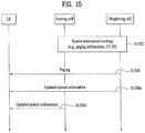
- FIG. 15 shows a signal transmission/reception method of Method 1.
- a serving cell may correspond to a pico cell and a neighbor cell may correspond to a macro cell.
- a UE may correspond to a UE (e.g., PUE) in an expansion region.
- the serving cell and the neighbor cell exchange system information (S1502).
- the system information may include information about system information change (e.g., information change, changed system information, etc.), system information, paging information, etc., for example.
- the system information may be transmitted from the serving cell to the neighbor cell or from the neighbor cell to the serving cell.
- the UE in the expansion region monitors a paging subframe set by the neighbor cell in order to receive paging (S1504).
- paging may be used to inform the UE that the system information has been changed in the serving cell.
- the updated system information of the serving cell may be received from the neighbor cell (S1506a) or from the serving cell (S1506b).
- the PUE in the expansion region may receive paging and RACH response from the macro cell.
- the PUE may be in the RRC_CONNECTED state or the RRC_IDLE state.
- the PUE is in the RRC_IDLE state.
- FIG. 16 shows a signal transmission/reception method of Method 2.
- a serving cell may correspond to a pico cell and a neighbor cell may correspond to a macro cell.
- a UE may correspond to a UE (e.g., PUE) in an expansion region.
- the UE transmits a random access preamble to the serving cell (S1602).
- the serving cell transmits random access response information (e.g., a preamble sequence, etc.) to the target cell (S1604).
- the neighbor cell transmits the random access response information to the UE (S1606).
- the UE transmits the random access preamble and then monitors a window for the random access response.
- the UE may omit operation for receiving the random access response (e.g., PDCCH reception/decoding or PDSCH reception/decoding) at a specific time interval within the window.
- the specific time interval includes a subframe set as an ABS.
- the UE transmits Message 3 (e.g., UL-SCH transport block) to the serving cell using scheduling information in the random access response (S1608).
- Message 3 e.g., UL-SCH transport block
- the present example corresponds to a contention-free based RACH.
- a contention resolution message may be received from the serving cell and/or the neighbor cell (not shown) after transmitting Message 3.
- the PUE in the expansion region is used for convenience and the PUE of the present invention is not identified according to geographical location.
- the PUE in the expansion region is located at a cell edge in terms of signal transmission/reception based on the strength or quality (e.g., RSRP, RSRP, etc.) of the signal measured by the PUE, rather than the actual geographical location of the PUE.
- the pico cell may transmit, to the PUE, information indicating whether the present invention is applied (e.g., 1-bit information) through higher layer signaling (e.g., RRC signaling or MAC signaling) or physical layer signaling (e.g., PDCCH). For example, if the 1-bit information is set to a specific value, the UE may perform UE operation in the expansion region described in Embodiments 1 to 4. If the 1-bit information is set to another value, the UE may perform normal UE operation.
- higher layer signaling e.g., RRC signaling or MAC signaling
- PDCCH physical layer signaling
- FIG. 17 shows a base station and a UE to which one embodiment of the present invention is applicable. If a relay is included in a wireless communication system, communication between the eNB and the relay is performed in a backhaul link and communication between the relay and the UE is performed in an access link. Accordingly, the eNB or UE shown in FIG. 17 may be replaced with the relay.
- the wireless communication system includes a base station (BS) 110 and a UE 120.
- the BS 110 includes a processor 112, a memory 114 and a radio frequency (RF) unit 116.
- the processor 112 may be configured to implement the procedures and/or methods proposed by the present invention.
- the memory 114 is connected to the processor 112 to store a variety of information related to operation of the processor 112.
- the RF unit 116 is connected to the processor 112 to transmit and/or receive a RF signal.
- the UE 120 includes a processor 122, a memory 124 and a radio frequency (RF) unit 126.
- the processor 122 may be configured to implement the procedures and/or methods proposed by the present invention.
- the memory 124 is connected to the processor 122 to store a variety of information related to operation of the processor 122.
- the RF unit 126 is connected to the processor 122 to transmit and/or receive an RF signal.
- the BS 110 and/or the UE 120 may have a single antenna or multiple antennas.
- the above-mentioned embodiments of the present invention are disclosed on the basis of a data communication relationship between a user equipment, a relay node and a base station. Specific operations to be conducted by the base station in the present invention may also be conducted by an upper node of the base station as necessary. In other words, it will be obvious to those skilled in the art that various operations for enabling the base station to communicate with the user equipment in a network composed of several network nodes including the base station will be conducted by the base station or other network nodes other than the base station.
- the term "Base Station” may be replaced with the terms fixed station, Node-B, eNode-B (eNB), or access point as necessary.
- the term “terminal” may also be replaced with the term User Equipment (UE), subscriber station (SS) or mobile subscriber station (MSS) as necessary.
- UE User Equipment
- SS subscriber station
- MSS mobile subscriber station
- the embodiments of the present invention can be implemented by a variety of means, for example, hardware, firmware, software, or a combination thereof.
- the present invention can be implemented through application specific integrated circuits (ASICs), digital signal processors (DSPs), digital signal processing devices (DSPDs), programmable logic devices (PLDs), field programmable gate arrays (FPGAs), a processor, a controller, a microcontroller, a microprocessor, etc.
- ASICs application specific integrated circuits
- DSPs digital signal processors
- DSPDs digital signal processing devices
- PLDs programmable logic devices
- FPGAs field programmable gate arrays
- processor a controller, a microcontroller, a microprocessor, etc.
- the present invention can be implemented in a variety of formats, for example, modules, procedures, functions, etc.
- Software code may be stored in a memory unit so as to be executed by a processor.
- the memory unit may be located inside or outside of the processor, so that it can communicate with the aforementioned processor via a variety of well-known parts.
- the present invention may be used for a wireless communication device such as a terminal or a base station.
Landscapes
- Engineering & Computer Science (AREA)
- Computer Networks & Wireless Communication (AREA)
- Signal Processing (AREA)
- Mobile Radio Communication Systems (AREA)
Claims (8)
- Procédé d'exécution d'une mesure de canal d'un équipement utilisateur, UE, (10, 120) dans un système de communication sans fil, le procédé consistant à recevoir (S1408) un message de commande de transfert intercellulaire provenant d'une première cellule pendant un transfert intercellulaire, caractérisé en ce que
le message de commande de transfert intercellulaire comprend des informations d'attribution de sous-trame d'une seconde cellule indiquant un motif de sous-trame lié à une mesure de canal ;
le procédé consiste à transmettre (S1410) un préambule de canal d'accès aléatoire, RACH, à la seconde cellule ;
le procédé consiste à recevoir (S1412) un message de réponse en réponse au préambule RACH provenant de la seconde cellule ; et en ce que
le procédé consiste à transmettre un rapport d'informations d'état de canal, CSI, à la seconde cellule, dans lequel le rapport CSI comprend le résultat d'une mesure exécutée par l'UE à l'aide d'un signal reçu de la seconde cellule dans le motif de sous-trame indiqué par les informations d'attribution de sous-trame, si le message de réponse comprend une demande de rapport CSI. - Procédé selon la revendication 1, dans lequel la première cellule est une cellule source et la seconde cellule est une cellule cible.
- Procédé selon la revendication 1, dans lequel le signal de la seconde cellule est reçu à l'aide des informations d'attribution de sous-trame dans le message de commande de transfert intercellulaire jusqu'à recevoir des informations d'attribution de sous-trame mises à jour.
- Procédé selon la revendication 3, dans lequel les informations d'attribution de sous-trame mises à jour sont reçues par le biais d'informations système ou d'une signalisation dédiée à l'UE (10, 120).
- Équipement utilisateur, UE, (10, 120) utilisé dans un système de communication sans fil, l'UE (10, 120) comprenant :une unité de fréquence radio, RF, (126) ; etun processeur (122) conçu pour commander l'unité RF (116),dans lequel le processeur (122) est conçu pour recevoir (S1408) un message de commande de transfert intercellulaire provenant d'une première cellule pendant un transfert intercellulaire, caractérisé en ce quele message de commande de transfert intercellulaire comprend des informations d'attribution de sous-trame d'une seconde cellule indiquant un motif de sous-trame lié à une mesure de canal ;le processeur (122) est conçu pour transmettre (S1410) un préambule de canal d'accès aléatoire, RACH, à la seconde cellule ;le processeur (122) est conçu pour recevoir (S1412) un message de réponse en réponse au préambule RACH provenant de la seconde cellule ; et en ce quele processeur (122) est conçu pour transmettre un rapport d'informations d'état de canal, CSI, à la seconde cellule, dans lequel le rapport CSI comprend le résultat d'une mesure exécutée par l'UE à l'aide d'un signal reçu de la seconde cellule à travers le motif de sous-trame indiqué par les informations d'attribution de sous-trame, si le message de réponse comprend une demande de rapport CSI.
- UE (10, 120) selon la revendication 5, dans lequel la première cellule est une cellule source et la seconde cellule est une cellule cible.
- UE (10, 120) selon la revendication 5, dans lequel le signal de la seconde cellule est reçu à l'aide des informations d'attribution de sous-trame dans le message de commande de transfert intercellulaire jusqu'à recevoir des informations d'attribution de sous-trame mises à jour.
- UE (10, 120) selon la revendication 7, dans lequel les informations d'attribution de sous-trame mises à jour sont reçues par le biais d'informations système ou d'une signalisation dédiée à l'UE (10, 120).
Applications Claiming Priority (3)
| Application Number | Priority Date | Filing Date | Title |
|---|---|---|---|
| US201161467371P | 2011-03-24 | 2011-03-24 | |
| US201161479846P | 2011-04-28 | 2011-04-28 | |
| PCT/KR2012/002065 WO2012128565A2 (fr) | 2011-03-24 | 2012-03-22 | Procédé de communication prenant en compte le brouillage entre les cellules dans un système de communication sans fil, et dispositif associé |
Publications (3)
| Publication Number | Publication Date |
|---|---|
| EP2690909A2 EP2690909A2 (fr) | 2014-01-29 |
| EP2690909A4 EP2690909A4 (fr) | 2015-04-15 |
| EP2690909B1 true EP2690909B1 (fr) | 2017-09-27 |
Family
ID=46879911
Family Applications (1)
| Application Number | Title | Priority Date | Filing Date |
|---|---|---|---|
| EP12760851.1A Not-in-force EP2690909B1 (fr) | 2011-03-24 | 2012-03-22 | Procédé permettant d'effectuer des mesures par un équipment utilisatuer |
Country Status (4)
| Country | Link |
|---|---|
| US (1) | US9538396B2 (fr) |
| EP (1) | EP2690909B1 (fr) |
| KR (1) | KR101887063B1 (fr) |
| WO (1) | WO2012128565A2 (fr) |
Cited By (1)
| Publication number | Priority date | Publication date | Assignee | Title |
|---|---|---|---|---|
| US20240172058A1 (en) * | 2021-03-11 | 2024-05-23 | Nokia Technologies Oy | Interference coordination for mobility |
Families Citing this family (14)
| Publication number | Priority date | Publication date | Assignee | Title |
|---|---|---|---|---|
| US8937918B2 (en) | 2011-10-29 | 2015-01-20 | Ofinno Technologies, Llc | Efficient special subframe allocation |
| US11696300B2 (en) | 2011-10-29 | 2023-07-04 | Comcast Cable Communications, Llc | Configuration of reduced transmission power time intervals based on traffic load |
| US8971250B2 (en) | 2011-10-29 | 2015-03-03 | Ofinno Technologies, Llc | Special subframe allocation |
| US8873467B2 (en) | 2011-12-05 | 2014-10-28 | Ofinno Technologies, Llc | Control channel detection |
| US8934436B2 (en) | 2011-12-31 | 2015-01-13 | Ofinno Technologies, L.L.C. | Special subframe configuration in wireless networks |
| TWI469599B (zh) * | 2012-06-08 | 2015-01-11 | Arcadyan Technology Corp | 無線行動通訊方法 |
| US9398548B2 (en) * | 2012-10-26 | 2016-07-19 | Lg Electronics Inc. | Interference control method in wireless communication system and apparatus for the same |
| US9544115B2 (en) * | 2013-08-19 | 2017-01-10 | Qualcomm Incorporated | Apparatus and method of improving identification of reference signal transmissions |
| US9713049B2 (en) * | 2014-04-28 | 2017-07-18 | Intel IP Corporation | User equipment and methods for measurement of reference signal received quality |
| CN105376812B (zh) * | 2014-08-29 | 2019-05-24 | 电信科学技术研究院 | 上行传输主载波切换及其控制方法、装置、基站及ue |
| WO2016137395A1 (fr) * | 2015-02-23 | 2016-09-01 | Agency For Science, Technology And Research | Procédés de radiocommunication et dispositifs de radiocommunication |
| WO2017015831A1 (fr) * | 2015-07-27 | 2017-02-02 | 华为技术有限公司 | Procédé de transmission d'informations et appareil associé |
| CN107889244B (zh) * | 2016-09-30 | 2020-06-02 | 华为技术有限公司 | 通信方法、装置及计算机可读存储介质 |
| US12015984B2 (en) | 2019-02-14 | 2024-06-18 | Sony Group Corporation | Terminal device, system and methods |
Family Cites Families (13)
| Publication number | Priority date | Publication date | Assignee | Title |
|---|---|---|---|---|
| JP2008103865A (ja) * | 2006-10-18 | 2008-05-01 | Nec Corp | ハンドオーバ制御システム及びその方法並びにそれを用いた移動通信システム及び無線基地局 |
| WO2008076073A1 (fr) * | 2006-12-19 | 2008-06-26 | Telefonaktiebolaget Lm Ericsson (Publ) | Procédé et agencement dans un système de télécommunication |
| US9307464B2 (en) * | 2007-06-21 | 2016-04-05 | Sony Corporation | Cellular communication system, apparatus and method for handover |
| KR101370909B1 (ko) * | 2007-10-01 | 2014-03-19 | 엘지전자 주식회사 | 핸드오버시 신속한 상향 데이터 전송방법 |
| KR101344400B1 (ko) * | 2007-11-29 | 2014-02-17 | 삼성전자 주식회사 | 기지국간 핸드오버시의 패킷 포워딩 방법 |
| WO2009123391A1 (fr) * | 2008-03-31 | 2009-10-08 | Lg Electronics Inc. | Rapport de mesures d'une station mobile à un réseau et procédé de commande de transfert associé |
| US8442069B2 (en) * | 2008-04-14 | 2013-05-14 | Qualcomm Incorporated | System and method to enable uplink control for restricted association networks |
| WO2010121418A1 (fr) * | 2009-04-21 | 2010-10-28 | Huawei Technologies Co., Ltd. | Procédé d'identification de problème de transfert intercellulaire |
| EP2282575A1 (fr) * | 2009-08-04 | 2011-02-09 | Panasonic Corporation | Rapport de qualité de canal dans un système de communication mobile |
| US9807633B2 (en) * | 2010-11-05 | 2017-10-31 | Google Technology Holdings LLC | Configuring unscheduled periods to enable interference reduction in heterogeneous networks |
| US20120122472A1 (en) * | 2010-11-12 | 2012-05-17 | Motorola Mobility, Inc. | Positioning Reference Signal Assistance Data Signaling for Enhanced Interference Coordination in a Wireless Communication Network |
| KR101587434B1 (ko) * | 2011-09-29 | 2016-01-21 | 노키아 솔루션스 앤드 네트웍스 오와이 | 부하에 기초한 핸드오버 관리 |
| US8903399B2 (en) * | 2011-11-04 | 2014-12-02 | Telefonaktiebolaget L M Ericsson (Publ) | Methods and network nodes for detecting short stay handover |
-
2012
- 2012-03-22 EP EP12760851.1A patent/EP2690909B1/fr not_active Not-in-force
- 2012-03-22 WO PCT/KR2012/002065 patent/WO2012128565A2/fr not_active Ceased
- 2012-03-22 KR KR1020137020774A patent/KR101887063B1/ko not_active Expired - Fee Related
- 2012-03-22 US US14/005,448 patent/US9538396B2/en not_active Expired - Fee Related
Non-Patent Citations (1)
| Title |
|---|
| None * |
Cited By (2)
| Publication number | Priority date | Publication date | Assignee | Title |
|---|---|---|---|---|
| US20240172058A1 (en) * | 2021-03-11 | 2024-05-23 | Nokia Technologies Oy | Interference coordination for mobility |
| US12581375B2 (en) * | 2021-03-11 | 2026-03-17 | Nokia Technologies Oy | Interference coordination for mobility |
Also Published As
| Publication number | Publication date |
|---|---|
| EP2690909A2 (fr) | 2014-01-29 |
| KR101887063B1 (ko) | 2018-09-10 |
| US9538396B2 (en) | 2017-01-03 |
| WO2012128565A2 (fr) | 2012-09-27 |
| KR20140010030A (ko) | 2014-01-23 |
| EP2690909A4 (fr) | 2015-04-15 |
| WO2012128565A3 (fr) | 2013-01-03 |
| US20140003250A1 (en) | 2014-01-02 |
Similar Documents
| Publication | Publication Date | Title |
|---|---|---|
| EP2690909B1 (fr) | Procédé permettant d'effectuer des mesures par un équipment utilisatuer | |
| US11064379B2 (en) | Method and apparatus for measuring D2D signal or selecting relay in wireless communication system | |
| CN110249657B (zh) | 在无线通信系统中通过终端监测无线链路的方法和支持该方法的设备 | |
| JP6412255B2 (ja) | 無線通信システムにおいてデバイス間の通信を行う方法及びこれを行う装置 | |
| KR102078370B1 (ko) | 무선 통신 시스템에서 단말의 측정 수행 방법 및 이를 위한 장치 | |
| JP6479976B2 (ja) | 無線通信システムにおけるd2d信号送受信方法及びそのための装置 | |
| US10178575B2 (en) | Method and apparatus for supporting full-duplex communication operation in wireless communication system supporting full-duplex communication | |
| US9307437B2 (en) | Method for measuring cell in wireless access system, and device therefor | |
| CN104145431B (zh) | 用于终端在无线通信系统中接收下行链路信号的方法及其装置 | |
| KR102047705B1 (ko) | 무선 통신 시스템에서 단말이 상향링크 송신 전력을 결정하는 방법 및 이를 위한 장치 | |
| US9313817B2 (en) | Method for performing D2D communication and apparatus therefor | |
| US9161370B2 (en) | Method and device for resolving interference between cells | |
| US20180020457A1 (en) | Method for allocating resource by considering inter-device interference in full-duplex wireless communication system and apparatus therefor | |
| CN104904138B (zh) | 多小区无线通信系统中共享无线电资源信息的方法及设备 | |
| EP3430857A1 (fr) | Accès aléatoire à base de contention dans un spectre sans licence | |
| JP6388963B2 (ja) | 無線通信システムにおいてD2D(Device−to−Device)信号送信方法及びそのための装置 | |
| WO2013129871A1 (fr) | Procédé permettant de réduire les interférences intercellulaires dans un système de communication sans fil multicellulaire coopérative, et appareil associé | |
| CN104081698B (zh) | 在无线通信系统中收发下行链路控制信道的方法及其设备 | |
| US9521654B2 (en) | Method for estimating channel in wireless access system and apparatus for same | |
| CN104321987B (zh) | 在无线接入系统中估计abs区域的方法及其装置 | |
| US10291337B2 (en) | Method and device for measuring by using terminal in wireless communication system | |
| US20170303282A1 (en) | D2d relay method of terminal in wireless communication system, and apparatus therefor |
Legal Events
| Date | Code | Title | Description |
|---|---|---|---|
| PUAI | Public reference made under article 153(3) epc to a published international application that has entered the european phase |
Free format text: ORIGINAL CODE: 0009012 |
|
| 17P | Request for examination filed |
Effective date: 20131017 |
|
| AK | Designated contracting states |
Kind code of ref document: A2 Designated state(s): AL AT BE BG CH CY CZ DE DK EE ES FI FR GB GR HR HU IE IS IT LI LT LU LV MC MK MT NL NO PL PT RO RS SE SI SK SM TR |
|
| DAX | Request for extension of the european patent (deleted) | ||
| REG | Reference to a national code |
Ref country code: DE Ref legal event code: R079 Ref document number: 602012037853 Country of ref document: DE Free format text: PREVIOUS MAIN CLASS: H04W0036300000 Ipc: H04W0036000000 |
|
| A4 | Supplementary search report drawn up and despatched |
Effective date: 20150318 |
|
| RIC1 | Information provided on ipc code assigned before grant |
Ipc: H04W 36/00 20090101AFI20150312BHEP |
|
| 17Q | First examination report despatched |
Effective date: 20161026 |
|
| GRAP | Despatch of communication of intention to grant a patent |
Free format text: ORIGINAL CODE: EPIDOSNIGR1 |
|
| INTG | Intention to grant announced |
Effective date: 20170223 |
|
| GRAS | Grant fee paid |
Free format text: ORIGINAL CODE: EPIDOSNIGR3 |
|
| GRAJ | Information related to disapproval of communication of intention to grant by the applicant or resumption of examination proceedings by the epo deleted |
Free format text: ORIGINAL CODE: EPIDOSDIGR1 |
|
| GRAL | Information related to payment of fee for publishing/printing deleted |
Free format text: ORIGINAL CODE: EPIDOSDIGR3 |
|
| INTC | Intention to grant announced (deleted) | ||
| GRAR | Information related to intention to grant a patent recorded |
Free format text: ORIGINAL CODE: EPIDOSNIGR71 |
|
| GRAA | (expected) grant |
Free format text: ORIGINAL CODE: 0009210 |
|
| AK | Designated contracting states |
Kind code of ref document: B1 Designated state(s): AL AT BE BG CH CY CZ DE DK EE ES FI FR GB GR HR HU IE IS IT LI LT LU LV MC MK MT NL NO PL PT RO RS SE SI SK SM TR |
|
| INTG | Intention to grant announced |
Effective date: 20170821 |
|
| REG | Reference to a national code |
Ref country code: GB Ref legal event code: FG4D |
|
| REG | Reference to a national code |
Ref country code: CH Ref legal event code: EP |
|
| REG | Reference to a national code |
Ref country code: AT Ref legal event code: REF Ref document number: 933066 Country of ref document: AT Kind code of ref document: T Effective date: 20171015 |
|
| REG | Reference to a national code |
Ref country code: IE Ref legal event code: FG4D |
|
| REG | Reference to a national code |
Ref country code: DE Ref legal event code: R096 Ref document number: 602012037853 Country of ref document: DE |
|
| PG25 | Lapsed in a contracting state [announced via postgrant information from national office to epo] |
Ref country code: NO Free format text: LAPSE BECAUSE OF FAILURE TO SUBMIT A TRANSLATION OF THE DESCRIPTION OR TO PAY THE FEE WITHIN THE PRESCRIBED TIME-LIMIT Effective date: 20171227 Ref country code: LT Free format text: LAPSE BECAUSE OF FAILURE TO SUBMIT A TRANSLATION OF THE DESCRIPTION OR TO PAY THE FEE WITHIN THE PRESCRIBED TIME-LIMIT Effective date: 20170927 Ref country code: HR Free format text: LAPSE BECAUSE OF FAILURE TO SUBMIT A TRANSLATION OF THE DESCRIPTION OR TO PAY THE FEE WITHIN THE PRESCRIBED TIME-LIMIT Effective date: 20170927 Ref country code: SE Free format text: LAPSE BECAUSE OF FAILURE TO SUBMIT A TRANSLATION OF THE DESCRIPTION OR TO PAY THE FEE WITHIN THE PRESCRIBED TIME-LIMIT Effective date: 20170927 Ref country code: FI Free format text: LAPSE BECAUSE OF FAILURE TO SUBMIT A TRANSLATION OF THE DESCRIPTION OR TO PAY THE FEE WITHIN THE PRESCRIBED TIME-LIMIT Effective date: 20170927 |
|
| REG | Reference to a national code |
Ref country code: NL Ref legal event code: MP Effective date: 20170927 |
|
| REG | Reference to a national code |
Ref country code: LT Ref legal event code: MG4D |
|
| REG | Reference to a national code |
Ref country code: AT Ref legal event code: MK05 Ref document number: 933066 Country of ref document: AT Kind code of ref document: T Effective date: 20170927 |
|
| PG25 | Lapsed in a contracting state [announced via postgrant information from national office to epo] |
Ref country code: BG Free format text: LAPSE BECAUSE OF FAILURE TO SUBMIT A TRANSLATION OF THE DESCRIPTION OR TO PAY THE FEE WITHIN THE PRESCRIBED TIME-LIMIT Effective date: 20171227 Ref country code: GR Free format text: LAPSE BECAUSE OF FAILURE TO SUBMIT A TRANSLATION OF THE DESCRIPTION OR TO PAY THE FEE WITHIN THE PRESCRIBED TIME-LIMIT Effective date: 20171228 Ref country code: RS Free format text: LAPSE BECAUSE OF FAILURE TO SUBMIT A TRANSLATION OF THE DESCRIPTION OR TO PAY THE FEE WITHIN THE PRESCRIBED TIME-LIMIT Effective date: 20170927 Ref country code: LV Free format text: LAPSE BECAUSE OF FAILURE TO SUBMIT A TRANSLATION OF THE DESCRIPTION OR TO PAY THE FEE WITHIN THE PRESCRIBED TIME-LIMIT Effective date: 20170927 |
|
| PG25 | Lapsed in a contracting state [announced via postgrant information from national office to epo] |
Ref country code: NL Free format text: LAPSE BECAUSE OF FAILURE TO SUBMIT A TRANSLATION OF THE DESCRIPTION OR TO PAY THE FEE WITHIN THE PRESCRIBED TIME-LIMIT Effective date: 20170927 |
|
| PG25 | Lapsed in a contracting state [announced via postgrant information from national office to epo] |
Ref country code: CZ Free format text: LAPSE BECAUSE OF FAILURE TO SUBMIT A TRANSLATION OF THE DESCRIPTION OR TO PAY THE FEE WITHIN THE PRESCRIBED TIME-LIMIT Effective date: 20170927 Ref country code: ES Free format text: LAPSE BECAUSE OF FAILURE TO SUBMIT A TRANSLATION OF THE DESCRIPTION OR TO PAY THE FEE WITHIN THE PRESCRIBED TIME-LIMIT Effective date: 20170927 Ref country code: RO Free format text: LAPSE BECAUSE OF FAILURE TO SUBMIT A TRANSLATION OF THE DESCRIPTION OR TO PAY THE FEE WITHIN THE PRESCRIBED TIME-LIMIT Effective date: 20170927 |
|
| PG25 | Lapsed in a contracting state [announced via postgrant information from national office to epo] |
Ref country code: IT Free format text: LAPSE BECAUSE OF FAILURE TO SUBMIT A TRANSLATION OF THE DESCRIPTION OR TO PAY THE FEE WITHIN THE PRESCRIBED TIME-LIMIT Effective date: 20170927 Ref country code: IS Free format text: LAPSE BECAUSE OF FAILURE TO SUBMIT A TRANSLATION OF THE DESCRIPTION OR TO PAY THE FEE WITHIN THE PRESCRIBED TIME-LIMIT Effective date: 20180127 Ref country code: EE Free format text: LAPSE BECAUSE OF FAILURE TO SUBMIT A TRANSLATION OF THE DESCRIPTION OR TO PAY THE FEE WITHIN THE PRESCRIBED TIME-LIMIT Effective date: 20170927 Ref country code: AT Free format text: LAPSE BECAUSE OF FAILURE TO SUBMIT A TRANSLATION OF THE DESCRIPTION OR TO PAY THE FEE WITHIN THE PRESCRIBED TIME-LIMIT Effective date: 20170927 Ref country code: SM Free format text: LAPSE BECAUSE OF FAILURE TO SUBMIT A TRANSLATION OF THE DESCRIPTION OR TO PAY THE FEE WITHIN THE PRESCRIBED TIME-LIMIT Effective date: 20170927 Ref country code: SK Free format text: LAPSE BECAUSE OF FAILURE TO SUBMIT A TRANSLATION OF THE DESCRIPTION OR TO PAY THE FEE WITHIN THE PRESCRIBED TIME-LIMIT Effective date: 20170927 |
|
| REG | Reference to a national code |
Ref country code: DE Ref legal event code: R097 Ref document number: 602012037853 Country of ref document: DE |
|
| PG25 | Lapsed in a contracting state [announced via postgrant information from national office to epo] |
Ref country code: DK Free format text: LAPSE BECAUSE OF FAILURE TO SUBMIT A TRANSLATION OF THE DESCRIPTION OR TO PAY THE FEE WITHIN THE PRESCRIBED TIME-LIMIT Effective date: 20170927 |
|
| PLBE | No opposition filed within time limit |
Free format text: ORIGINAL CODE: 0009261 |
|
| STAA | Information on the status of an ep patent application or granted ep patent |
Free format text: STATUS: NO OPPOSITION FILED WITHIN TIME LIMIT |
|
| PG25 | Lapsed in a contracting state [announced via postgrant information from national office to epo] |
Ref country code: PL Free format text: LAPSE BECAUSE OF FAILURE TO SUBMIT A TRANSLATION OF THE DESCRIPTION OR TO PAY THE FEE WITHIN THE PRESCRIBED TIME-LIMIT Effective date: 20170927 |
|
| 26N | No opposition filed |
Effective date: 20180628 |
|
| REG | Reference to a national code |
Ref country code: CH Ref legal event code: PL |
|
| GBPC | Gb: european patent ceased through non-payment of renewal fee |
Effective date: 20180322 |
|
| PG25 | Lapsed in a contracting state [announced via postgrant information from national office to epo] |
Ref country code: SI Free format text: LAPSE BECAUSE OF FAILURE TO SUBMIT A TRANSLATION OF THE DESCRIPTION OR TO PAY THE FEE WITHIN THE PRESCRIBED TIME-LIMIT Effective date: 20170927 Ref country code: MC Free format text: LAPSE BECAUSE OF FAILURE TO SUBMIT A TRANSLATION OF THE DESCRIPTION OR TO PAY THE FEE WITHIN THE PRESCRIBED TIME-LIMIT Effective date: 20170927 |
|
| REG | Reference to a national code |
Ref country code: BE Ref legal event code: MM Effective date: 20180331 |
|
| REG | Reference to a national code |
Ref country code: IE Ref legal event code: MM4A |
|
| PG25 | Lapsed in a contracting state [announced via postgrant information from national office to epo] |
Ref country code: LU Free format text: LAPSE BECAUSE OF NON-PAYMENT OF DUE FEES Effective date: 20180322 |
|
| PG25 | Lapsed in a contracting state [announced via postgrant information from national office to epo] |
Ref country code: IE Free format text: LAPSE BECAUSE OF NON-PAYMENT OF DUE FEES Effective date: 20180322 |
|
| PG25 | Lapsed in a contracting state [announced via postgrant information from national office to epo] |
Ref country code: GB Free format text: LAPSE BECAUSE OF NON-PAYMENT OF DUE FEES Effective date: 20180322 Ref country code: LI Free format text: LAPSE BECAUSE OF NON-PAYMENT OF DUE FEES Effective date: 20180331 Ref country code: CH Free format text: LAPSE BECAUSE OF NON-PAYMENT OF DUE FEES Effective date: 20180331 Ref country code: BE Free format text: LAPSE BECAUSE OF NON-PAYMENT OF DUE FEES Effective date: 20180331 |
|
| PG25 | Lapsed in a contracting state [announced via postgrant information from national office to epo] |
Ref country code: FR Free format text: LAPSE BECAUSE OF NON-PAYMENT OF DUE FEES Effective date: 20180331 |
|
| PG25 | Lapsed in a contracting state [announced via postgrant information from national office to epo] |
Ref country code: MT Free format text: LAPSE BECAUSE OF NON-PAYMENT OF DUE FEES Effective date: 20180322 |
|
| PG25 | Lapsed in a contracting state [announced via postgrant information from national office to epo] |
Ref country code: TR Free format text: LAPSE BECAUSE OF FAILURE TO SUBMIT A TRANSLATION OF THE DESCRIPTION OR TO PAY THE FEE WITHIN THE PRESCRIBED TIME-LIMIT Effective date: 20170927 |
|
| PGFP | Annual fee paid to national office [announced via postgrant information from national office to epo] |
Ref country code: DE Payment date: 20200211 Year of fee payment: 9 |
|
| PG25 | Lapsed in a contracting state [announced via postgrant information from national office to epo] |
Ref country code: PT Free format text: LAPSE BECAUSE OF FAILURE TO SUBMIT A TRANSLATION OF THE DESCRIPTION OR TO PAY THE FEE WITHIN THE PRESCRIBED TIME-LIMIT Effective date: 20170927 Ref country code: HU Free format text: LAPSE BECAUSE OF FAILURE TO SUBMIT A TRANSLATION OF THE DESCRIPTION OR TO PAY THE FEE WITHIN THE PRESCRIBED TIME-LIMIT; INVALID AB INITIO Effective date: 20120322 |
|
| PG25 | Lapsed in a contracting state [announced via postgrant information from national office to epo] |
Ref country code: MK Free format text: LAPSE BECAUSE OF NON-PAYMENT OF DUE FEES Effective date: 20170927 Ref country code: CY Free format text: LAPSE BECAUSE OF FAILURE TO SUBMIT A TRANSLATION OF THE DESCRIPTION OR TO PAY THE FEE WITHIN THE PRESCRIBED TIME-LIMIT Effective date: 20170927 |
|
| PG25 | Lapsed in a contracting state [announced via postgrant information from national office to epo] |
Ref country code: AL Free format text: LAPSE BECAUSE OF FAILURE TO SUBMIT A TRANSLATION OF THE DESCRIPTION OR TO PAY THE FEE WITHIN THE PRESCRIBED TIME-LIMIT Effective date: 20170927 |
|
| REG | Reference to a national code |
Ref country code: DE Ref legal event code: R119 Ref document number: 602012037853 Country of ref document: DE |
|
| PG25 | Lapsed in a contracting state [announced via postgrant information from national office to epo] |
Ref country code: DE Free format text: LAPSE BECAUSE OF NON-PAYMENT OF DUE FEES Effective date: 20211001 |