EP2691685B1 - Outil de pipeline - Google Patents
Outil de pipeline Download PDFInfo
- Publication number
- EP2691685B1 EP2691685B1 EP11716390.7A EP11716390A EP2691685B1 EP 2691685 B1 EP2691685 B1 EP 2691685B1 EP 11716390 A EP11716390 A EP 11716390A EP 2691685 B1 EP2691685 B1 EP 2691685B1
- Authority
- EP
- European Patent Office
- Prior art keywords
- pipeline
- tool
- hydraulic
- pipeline tool
- hydraulic system
- Prior art date
- Legal status (The legal status is an assumption and is not a legal conclusion. Google has not performed a legal analysis and makes no representation as to the accuracy of the status listed.)
- Active
Links
Images


Classifications
-
- F—MECHANICAL ENGINEERING; LIGHTING; HEATING; WEAPONS; BLASTING
- F16—ENGINEERING ELEMENTS AND UNITS; GENERAL MEASURES FOR PRODUCING AND MAINTAINING EFFECTIVE FUNCTIONING OF MACHINES OR INSTALLATIONS; THERMAL INSULATION IN GENERAL
- F16L—PIPES; JOINTS OR FITTINGS FOR PIPES; SUPPORTS FOR PIPES, CABLES OR PROTECTIVE TUBING; MEANS FOR THERMAL INSULATION IN GENERAL
- F16L55/00—Devices or appurtenances for use in, or in connection with, pipes or pipe systems
- F16L55/26—Pigs or moles, i.e. devices movable in a pipe or conduit with or without self-contained propulsion means
- F16L55/28—Constructional aspects
- F16L55/30—Constructional aspects of the propulsion means, e.g. towed by cables
- F16L55/32—Constructional aspects of the propulsion means, e.g. towed by cables being self-contained
- F16L55/34—Constructional aspects of the propulsion means, e.g. towed by cables being self-contained the pig or mole being moved step by step
Definitions
- the present invention relates to a pipeline tool in particular to a robotic pipeline tool suitable for pushing or pulling other pipeline tools such as an autonomous isolation tool within a pipeline.
- a fluid pigging medium selected from one or more of the following examples water, oil, condensate MEG (monoethylene glycol), air, nitrogen or the pipeline's own gas product.
- a particular problem associated with moving or pigging a tool to a desired location in a gas pipeline system using water is the possibility of water by-pass and consequently formation of hydrates. Hydrates can cause a blockage in a pipeline. Should hydrates form in a pipeline it is then necessary to insert a specialist piece of equipment or introduces a chemical agent into the pipeline to breakdown the blockage. Other problems include corrosion from the introduction of water which is detrimental to the overall integrity of the pipeline system, Other problems include backing strips at the field joint weld location in some pipelines, which makes pigging difficult.
- Major gas pipeline transportation systems require regular planned double block and bleed isolation, in order to conduct servicing on the valve systems at their upstream or downstream terminals.
- Northwest European gas transportation pipeline systems include for example; Ref Name Length Diameter 1 Bacton to Zeebrugge UK Interconnector 233km 40 inch 2 Zeepipe Norway to Belgium 814km 40 inch 3 Balzand Interconnector 235km 36 inch 4 Europipe 1 Norway to Germany 660km 40 inch 5 Europipe 2 Norway to Germany 642km 42 inch 6 Norpipe 440km 36 inch 7 Franpipe Norway to France 840km 42 inch 8 Ormen Lange Norway to England 1166km 44 inch 9 SNIP Scotland to Northern Ireland 50km 24 inch 10 Eire Interconnector Scotland to Ireland 190km 24 inch 11 Eire Interconnector 2 Scotland to Ireland 194km 30 inch 12 Statpipe Norway to Germany 882km 28/36 in 13 FLAGGS to UK 448km 36 inch 14 Frigg St Fergus 2x360km 2x32 in 15 LOGGS
- a tool according to the preamble of claim 1 is known from document WO-A-2005/061944 .
- the present invention provides a pipeline tool as set out in the appended Claims 1 to 17.
- this tool is that it is self-propelled, thus it is moveable to an accurate location within a pipeline without the use of water, or a propelling medium thereby eliminating the requirement to introduce a pushing fluid and its associated hazards.
- the pipeline tool is connectable to another pipeline tool for example, a pipeline isolation tool. Consequently the pipeline tool of the invention provides a means for moving or accurately locating another pipeline tool at a desired location within a pipeline.
- the pipeline tool of the present invention is suitable for use in straight pipe.
- a pipeline has a plurality of valves at the termination points of the pipeline in order to retain the contents of the pipeline. These valves require maintenance or replacing over time.
- the pipeline tool of the present invention is particularly suitable for use in the straight sections of pipe positioned at pipeline termination points especially the sections of pipe associated with autonomous intervention into main pipeline transportation systems.
- the applicant has a further invention relating to a pipeline tool that is suitable for positioning of autonomous isolation tools or other equipment in pipeline locations where bends, branching Y's, Tees or risers have to be negotiated before the equipment reaches the desired location.
- This further invention is the subject of another International Patent Application.
- control unit of the pipeline tool is provided as a control pod which contains at least one microprocessor.
- microprocessors there are at least two microprocessors.
- microprocessors are programmed with an embedded software program. In this way the control unit is programmed to control the movement of the pipeline tool through a pipeline transportation system. Conveniently this enables the pipeline tool of the invention to move horizontally, up or down inclines, and to move a load vertically up or down a straight pipeline section.
- control unit further comprises a communications module which enables the pipeline tool to utilize ELF communications.
- control unit of the pipeline tool of the invention is completely autonomous.
- the pipeline tool comprises a primary and a backup hydraulic system.
- the primary and backup hydraulic system are completely independent from each other.
- the hydraulic system comprises at least one hydraulic piston or ram coupled to a plurality of fluid pipes and hydraulic fluid which flows around the hydraulic circuit to effect movement of the pipeline tool.
- each of the primary and backup hydraulic systems comprise a plurality of hydraulic pistons or rams, wherein at least one piston or ram is an axial piston or ram and at least one piston or ram is a longitudinal piston or ram.
- piston or ram are used interchangeably throughout the specification.
- the axial ram and longitudinal rams are arranged such that they are perpendicular to one another.
- each hydraulic system comprises at least nine rams wherein at least eight rams are axial rams and at least one ram is a longitudinal ram.
- each hydraulic system is arranged such that they are parallel to each other.
- the hydraulic ram of the backup hydraulic system remains recessed when not in use. The advantage of this is that it avoids interfering with the operation of the primary hydraulic system.
- the piston or ram of the backup hydraulic system is slightly shorter than the piston or ram of the primary hydraulic system.
- each of the axial hydraulic rams are arranged such that standard opposing forces principles enable each of the hydraulic rams to engage with the internal surface of the pipeline wall such that the pipeline tool remains in position within the pipeline regardless of the inclination of the pipeline or whether or not the surface of the pipeline is coated.
- each of the axial hydraulic rams are provided with a pipeline engaging means.
- the pipeline engaging means is a coated compression pad. This provides the compression pad with a surface which is tactile which promotes adhesion to the internal pipe wall surface.
- the compression pad is a rubber coated compression pad.
- the compression pad is a threaded compression pad. It is understood that any suitable coating which is known to a person skilled in the art can be used.
- control system of the pipeline tool monitors the operation of the hydraulic system.
- monitoring of the hydraulic system is achieved by using one or more various types of sensors such as pressure sensors and proximity sensors.
- the sensors monitor various pressure levels on the pipeline tool of the invention.
- the pressure levels between the pipeline engaging means and the interior surface of the pipeline For example, the pressure levels between the pipeline engaging means and the interior surface of the pipeline.
- a further example includes the pressure within the pipeline as detected by the first and second parts of the pipeline tool. It is to be understood that the examples given are not limiting and that a person skilled in the art can place sensors within the pipeline tool of the invention at any desired location.
- each of the sensors is provided with transmitters and receivers to enable transmission and receipt of information to and from the central processing unit.
- the central processing unit is programmed to detect whether or not the pressure levels detected by the sensors fall within predetermined parameters. In the event that the primary hydraulic unit fails, the central processing unit is able to switch to the backup hydraulic system.
- the means for operating the hydraulic system of the pipeline tool comprises a pump for operating the rams and/or pistons, means for operating the pump, a plurality of fluid pipelines positioned between the pump and the hydraulic rams.
- the hydraulic system also comprises an accumulator positioned in parallel with the pump.
- the hydraulic system of the pipeline tool is provided with one or more check valves and/or controllers which control the flow of hydraulic fluid around the hydraulic circuit to control the movement of the pipeline engaging means and the first and second parts such that the pipeline tool propels in a controlled manner, a pipeline isolation tool along the inside of a pipeline.
- valves of the hydraulic system are arranged in such a way to achieve a triple redundancy fail safe unset system.
- the hydraulic system is an engine driven system.
- the pipeline tool is fully retractable from within a pipeline.
- the pipeline tool has a sleep mode which is operable when the propulsion means are not in use. Conveniently when the pipeline tool of the invention is in sleep mode, it is retractable and movable to a distant location within a pipeline using pigging means.
- the pipeline tool of the invention is coupled to a further pipeline tool such as an isolation plug, the pipeline tool of the invention is launched down the pipeline in sleep mode, once the pipeline tool has been moved the required distance, the pipeline tool is activated thus exiting sleep mode, the pipeline tool is then remotely operable to position the load to a precise location within the pipeline.
- the pipeline tool of the invention is fitted with pigging disks or coupled to a chaser pig. This ensure that the pipeline tool of the invention can be pigged back to the start point.
- the pipeline tool is movable to a location by deploying the pipeline tool from a launcher barrel.
- the pipeline tool can also be recovered into a launcher or receiver barrel.
- the size of the launcher or receiver barrel is irrelevant as a cartridge insert can be used to modify the sizing to the appropriate or desired size for the pipeline tool of the invention
- the pipeline tool of the invention is able to enter the pipeline at a launcher or receiver and travel along the pipeline system pulling or pushing a load such as a pipeline isolation tool.
- a load such as a pipeline isolation tool.
- the orientation of the pipeline or the direction of travel of the pipeline tool of the invention within the pipeline is irrelevant.
- the pipe within which the pipeline tool of the invention will travel can be horizontal, vertical or angled pipe wherein it is understood that horizontal is parallel to the x-axis, vertical is at right angles to the x-axis and angled is at any angle between an horizontal and vertical orientation.
- the pipeline tool of the invention can climb or descend whilst carrying or supporting a load within a vertical or angled pipe.
- the pipeline tool of the invention is able to position the load with extreme accuracy without the use of a fluid or an external propelling medium.
- the pipeline tool of the invention is further provided with a coupling mechanism which enables the pipeline tool to connect to a pipeline isolation tool or other technical equipment.
- the coupling mechanism comprises a double articulating ball and socket joint, a flexing spring joint, or a double acting universal joint.
- the pipeline tool of the present invention is suitable to support any other internal pipeline tool required within the industry.
- An example of other tools include a magnetic flux leakage train, a camera tool, a radiography tool, a hydrate buster, a paint application tool, or as a pulling pipeline tool for introducing fibre optic cables into old pipelines, or as an extraction tool without requirement to pig or flood a pipeline.
- a further advantage of the present invention is that in use it eliminates the requirement to flood, to dewater and then to vacuum dry or recondition the pipeline.
- the pipeline tool is coupled to a wheeled isolation tool comprising;
- the pipeline isolation tool comprises a mechanical isolation tool.
- the mechanical isolation tool can be located at either end of the pipeline tool of the invention.
- isolation tool and pipeline tool of the invention operate in an autonomous environment without either an umbilical or tether attached to the housing of the invention.
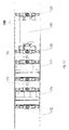
- FIG. 1 there is shown a pipeline tool 100 of the invention.
- Pipeline tool 100 comprises a control pod 130 which houses a pair of embedded microprocessors (not shown) and two hydraulic systems, hereinafter referred to as normal hydraulic system A and standby hydraulic system B.
- the components contained within the control pod 130 are housed in a one atmosphere (1 ata) pressurised housing.
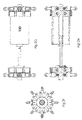
- Pipeline 100 of the invention also comprises two longitudinal rams 160a and 160b together with a plurality of axial rams 140A, 140B, 150A and 150B.
- a plurality of wheels 120 are provided at opposing ends of the pipeline tool 100 in a circular arrangement. The spring loaded wheels 120 function to hold the pipeline tool 100 in the centre of the pipeline thereby preventing the body of the pipeline tool 100 which houses the control pod 130 from coming into contact with the surfaces of the internal wall of the pipeline as shown in Figure 1 B and 1C .
- the pipeline tool 100 is provided with coupling means 170 which enables the pipeline tool 100 of the invention to couple to other items such as a pig train.
- Pipeline tool 100 can push or pull its load in either direction within the pipeline 172.
- pipeline tool 100 is coupled to a double module isolating plug 174.
- the double module isolating plug 174 is also provided with a number of circular wheel arrangements 120 to assist in movement of the pig train through the pipeline 172.
- the provision of the wheel arrangements 120 ensures that the pig train moves easily whilst being pushed or pulled through the pipeline 172, particularly given that the overall diameter of the double module isolating plug 174 is larger than that of the pipeline tool 100 of the invention.
- Coupling means 170 is in the form of an articulating double ball joint arrangement, wherein a ball connection is coupled to the socket 170A of the pipeline tool 100 as shown in Figures 1 B and 1C.
- the load coupled to the pipeline tool could also be, for example, any one of a single or triple module isolating plug, an intelligent pig, a gauge pig, a hydrate blaster or an internal paint coating tool or any other device.
- the pipeline tool 100 is also provided with a coupling means 170 at the opposing end of the pipeline tool 100.
- Either normal hydraulic system A or standby hydraulic system B is operated to move pipeline tool 100 through the pipeline 172.
- the main operational hydraulic system is normal hydraulic system A.
- hydraulic system B becomes the main operational hydraulic system to effect movement of the pipeline tool 100.
- the pipeline tool 100 can achieve this functionality even when the pipeline is in a fully vertical orientation, regardless of whether or not the internal wall of the pipeline is coated with a material having flow enhancing properties.
- the embedded microprocessors control the engine of the pipeline tool 100 which in turn drives the hydraulic ram systems A or B.
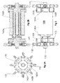
- Normal hydraulic system A and standby hydraulic system B each comprise eight segmented axial rams which are configured to provide maximum grip against the pipeline wall.
- the axial rams of hydraulic system A are divided such that four axial rams 140a are located at the first end of the pipeline tool 100 and four axial rams 150a are located at the second end of the pipeline tool 100.
- the axial rams of hydraulic system B are also divided such that four axial rams 140b are located at the first end of the pipeline tool 100 and four axial rams 150b are located at the second of the pipeline tool 100.
- the axial rams located at the first end of the pipeline tool are indicated collectively by reference numeral 140 and those at the second end of the pipeline tool are collectively indicated by reference numeral 150.
- normal hydraulic system A drives the axial rams 140A and 150A and longitudinal ram 160A.
- Standby hydraulic system B drives the axial rams 140B and 150B and longitudinal ram 160B.
- the microprocessors are nominated to respective sides of the pipeline tool 100 whereby side A of the control pod 130 corresponds to the first microprocessor which is in communication with normal hydraulic system A and side B of the control pod 130 corresponds to the second microprocessor which is in communication with standby hydraulic system B.
- the microprocessor at side A of the control pod 130 has priority until point of failure of side A. Failure of side A is subject to a set of system self diagnostics whereby the central processing unit 132 of the system diagnoses the status of various sensors 232, 234, 236, 238 and determines whether or not side A is operating within predetermined parameters. In the event that side A is operating outside the predetermined parameters then side A fails and side B takes control.
- the central processing unit 132 is provided with a self diagnostic system for the pipeline tool 100. A set of parameters or boundaries are provided which enable the central processing unit to determine when it is necessary and appropriate to allow side B to take control as determined in the resulting output 136.
- Each of hydraulic ram systems A and B are further provided with a longitudinal ram 160a and 160b respectively.
- Each longitudinal ram 160 is positioned perpendicular to the segmented axial rams 140 and 150 as shown in Figure 2B .
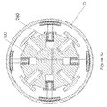
- the axial rams 140a of System A at the first and second ends of the pipeline tool 100 are arranged in a circular ring arrangement such that the angle between each consecutive axial ram of System A in the ring arrangement is approximately 90°.
- the axial rams 140b of System B are Interspaced between the axial rams 140a of System A such that the axial rams 140b of System B at the first and second ends of the pipeline tool 100 are also arranged in a circular ring arrangement whereby angle between each consecutive axial ram of System B in the ring arrangement is approximately 90°.
- the axial rams 140 and 150 of Systems A and B at the first and second ends of the pipeline tool 100 are arranged in the circular ring arrangement such that the angle between each consecutive axial ram in the ring arrangement is approximately 45°.
- Each of the axial rams 140 and 150 are provided with rubber soled compression segment pads (Gekos) 142 positioned substantially perpendicularly to the axial rams 140 and 150 respectively ( Fig 2 ).
- the gekos 142 follow the natural contour of the interior surface of the pipeline wall, such that the profile of each o matches the interior curvature of the inner surface of the pipeline wall.
- the gekos 142 are each threaded to achieve the maximum grip possible.
- Pipeline tool 100 moves upwards and downwards within a pipeline 30 as desired by means of the hydraulic systems A and B.
- each of the eight compression segment pads 142 at the extremity of axial rams 140a and 140b respectively are manipulated into the required position by separate hydraulically driven pistons 240 and 244 ( Figure 4 ).
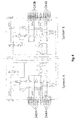
- Both hydraulic circuits for primary hydraulic system A and backup hydraulic system B are shown in Figure 4 .
- the axial ram sets of System A or axial ram sets of System B at the first and second ends of the pipeline tool may function at any one time.
- backup hydraulic system B operates in a similar manner.
- the pressure exerted by the axial compression pads 142 on the inner surface of the pipeline wall 172 are carefully calculated, to ensure sufficient compression is exerted on the pipeline wall whilst ensuring that the pressure exerted stays within allowable pipe hoop stress values. Furthermore, when pipelines are internally painted with a flow enhancing finish, it makes it extremely difficult for anything to cling to the wall, nonetheless the compression pads 142 use standard opposing forces principles to overcome the problems associated with coated finishes.
- each hydraulic engine of system A and system B also has separate pumps, gearboxes, motors, accumulators, system pressure vessels A and B, separate sensor system A and B for all hydraulic rams and pads, separate sensor systems A and B for orientation and attitude, separate command systems A and B, separate control systems A and B, separate sequencer systems A and B, separate battery systems A and B, separate power train systems A and B, full triple redundancy unset systems A and B, and separate ELF through pipe wall communications systems A and B.
- each of the independent rams 140A and 150A within hydraulic system A plus the ninth longitudinal ram 160A and the hydraulic system B unlatch mechanism, are driven by hydraulic pump 200A.
- Accumulator 202A is a pressurised reservoir which feeds oil into hydraulic pump 200A.
- Hydraulic pump 200A is driven by a motor 203A and gearbox 204A.
- each grouping of four axial A rams 140A and 150A correspond to axial hydraulic circuits 240A and 244A respectively.
- the ninth longitudinal ram 160A is marked as hydraulic circuit 242A.
- Fluid line 220A from hydraulic pump 200A feeds into hydraulic pistons 240A, 242A, and 244A through check valves 216A, valve controllers 210A, 212A and 214A and pressure transmitters 218A respectively.
- Each of the rams 140A and 140B on the hydraulic systems A and B are fitted with a return spring 260A as shown in Figure 3A .
- the axial rams have a reciprocating linear movement which is controlled by the hydraulic circuit and spring 260A.
- Each axial hydraulic system 240A and 244A has a controller in the form of a lock out pressure valve 210A and 214A respectively.
- Such a pressure valve 210A and 214A allows each axial ram 140A or 150A to move into an extended position whilst preventing the axial rams 140A or 150A from exerting too much pressure or imparting excessive hoop stress into the pipe wall.
- springs 260A are compressed.
- the compressed springs 260A recover their memory drawing the axial rams 140A and 150A away from the pipeline wall.
- the controllers 210A and 214A are indexed to a certain point which ensures that the axial compression rams 140A and 150A do not exert excessive pressure onto the pipe wall.
- Both longitudinal ram systems 160A and 160B cannot operate simultaneously.
- the longitudinal rams 160A and 160B are fitted with spring loaded latching mechanisms.
- the energy to compress the spring to unlatch and release the longitudinal rams 160A and 160B in use, can only be initiated by hydraulic pressure.
- the hydraulic pressure to conduct this function on the B latching spring comes from the primary hydraulic system A.
- the hydraulic pressure to conduct this function on the A latching spring comes from the B system. This ensures the secondary B longitudinal ram system is engaged and fully latched, before the A longitudinal ram system unlatching system is hydraulically activated, unlatched and released, thus allowing longitudinal ram 160A to be relocated in its receiver.
- Valve 310A controls the operation of the spring loaded latching mechanism for 160B at 246B however 246B is physically located within the A side hydraulic system circuit.
- Valve 310B (located within the B hydraulic system) controls the operation of the spring loaded latching mechanism for 160A at 246A , which is located within the B side hydraulic system circuit.
- Each hydraulic circuit of the invention (side A and side B) is also provided with a triple redundancy fail safe unset system which ensures that the pipeline tool of the invention can be decoupled from engagement with the pipeline wall, and returned to the pipeline start point.
- the triple redundancy fail safe unset system comprises an independent primary, secondary, and tertiary unset system.
- the primary unset system is a normal independent unset system which is operated using extremely low frequency (ELF) communications to move Valves 210A and 212A and 214A into an open position to unload the hydraulic fluid back to the accumulator 202A and thereby unlock the ram systems.
- ELF extremely low frequency
- the secondary unset system comprises a hyberbaric or hydrostatic upset unset system whereby a pre-set integrated detenting pressure release valve 320A detects a hyperbaric spike.
- the pressure build up when it reaches a certain value, causes a piston to move which drives a shuttle within the detenting valve 330A forward causing the integrated detenting valve to deflect and latch, thereby releasing the pressure and fluid from the circuit back to accumulator 202A.
- the tertiary unset system comprises a timed decay unset system, whereby valve 300a is triggered to depressurize the circuit once a predetermined measure has been reached, for example a 10 day countdown.
- the ninth ram 160A of primary hydraulic system A and 160B of backup hydraulic system B is longitudinal, and is located in the central line of the control pod, and is the motive force for driving the pipeline tool 100 up or down the pipeline.
- Ram 160A is referred to as 'middle' for the purposes of the sequencer process table below.
- the set of axial compression segment pads fitted to control pod 130 and known as 150 are referred to as bottom for the purposes of the sequencer process table below.
- the second set of axial compression segment pads 140 (meaning either system A or system B) are referred to as top for the purposes of the sequencer process table below.
- Control of movement of the pipeline tool 100 up or down the pipeline is managed by use of a sequencer process. An example of how the logic works is presented in the sequencer process table below. Movement of the pipeline tool 100 will now be described with reference to the Sequenser Process Table below; Sequenser Process Table Step Bottom Middle Top Remarks 1 Extended Retracted Extended No movement
- Axial compression segment pads 150 are extended and engage with the inner surface of the pipeline wall.
- Ninth ram 160 is retracted.
- Axial compression segment pads 140 are extended and engage with the inner surface of the pipeline wall.
- CHECK CONDITION 2 Extended Retracted Retracting Moving Axial compression segment pads 150 are extended and engage with the inner surface of the pipeline wall. Ninth ram 160 is retracted Axial compression segment pads 140 are disengaging with the inner surface of the pipeline wall. Retracting Top pads 140 move away from pipe wall. Pipeline tool is held on by bottom pads 150. 3 Extended Extending Retracted Moving Axial compression segment pads 150 remain extended and engaged with the inner surface of the pipeline wall. Ninth ram 160 is extending Axial compression segment pads 140 remain retracted. Extending main cylinder to push rapid set isolation tool up pipe on ninth ram 160. Pipeline tool is locked on by bottom pads 150.
- Bottom pads 150 are lifted off pipe wall Pipeline tool is locked on by top pads 140 6 Retracted Retracting Extended Moving Axial compression segment pads 150 remain retracted Ninth ram 160 is retracting Axial compression segment pads 140 remain extended and engaged with the inner surface of the pipeline wall. Main longitudinal ram is used to pull pipeline tool up the pipeline to next step. Pipeline tool is locked on by top pads 140 7 Extending Retracted Extended Moving Axial compression segment pads 150 are extended and engage with the inner surface of the pipeline wall. Ninth ram 160 is retracted Axial compression segment pads 140 remain extended and engaged with the inner surface of the pipeline wall. Bottom pads 150 are extended back onto pipe wall at new higher position.
- Pipeline tool is locked on with top 140 and bottom 150 pads CHECK CONDITION Back To Step 1 again 1 Extended Retracted Extended No movement Axial compression segment pads 150 are extended and engage with the inner surface of the pipeline wall. Ninth ram 160 is retracted. Axial compression segment pads 140 are extended and engage with the inner surface of the pipeline wall. Pipeline tool is locked on all 9 hydraulic rams 140 and150 and 160 Ready to start next full sequence
- up, down, left and right are used to leverage the axial rams against the pipeline wall 172 to grip the pipe wall.
- the longitudinal ram is extended which has the effect of moving the pipeline tool 100 up or down the pipeline thereby effecting movement of the pipeline tool 100.
- Each of the axial rams at the first and second ends provides a gripping force whilst the longitudinal ram 160 pushes the propulsion tool 100 forward or backwards.
- an isotope can be mounted at some known radial point on the pipeline tool 100 to provide positioning information to external scintillating detectors.
- Pipeline tool 100 can also be fitted with backup pigging disks, to enable it to be pigged out of the pipeline, by a propelled chaser pig if so desired.
- the central processing unit 132 is further provided with a mechanism by which it can calculate the distance travelled from the number of longitudinal piston strokes of the axial hydraulic ram system A or B.
- the pipeline tool 100 is made from suitable light-weight material which gives the tool high strength to weight ratios, examples of such light-weight material include titanium 6Al 4V or carbon fibre, however any suitable material known to a person skilled in the art can be used.
Landscapes
- Engineering & Computer Science (AREA)
- Chemical & Material Sciences (AREA)
- Combustion & Propulsion (AREA)
- General Engineering & Computer Science (AREA)
- Mechanical Engineering (AREA)
- Pipeline Systems (AREA)
Claims (17)
- Outil autonome pour pipeline (100), comprenant :un dispositif comprenantun premier composant et un deuxième composant, les premier et deuxième composants pouvant être séparés l'un de l'autre ;un système hydraulique (A,B) comprenant au moins un piston hydraulique (140, 150, 160) et un dispositif d'actionnement du piston, le système hydraulique pouvant être actionné pour séparer de façon réversible les premier et le deuxième composants du dispositif ; le système hydraulique possédant une pluralité de dispositifs d'engagement de pipeline (142) positionnés le long d'une surface extérieure du dispositif, les dispositifs d'engagement de pipeline étant actionnables par le système hydraulique pour s'engager avec la surface intérieure du pipeline (172) ; et une unité de commande (130), l'unité de commande étant en communication avec le système hydraulique pour commander les déplacements des dispositifs d'engagement de pipeline ainsi que les premier et le deuxième composants, de sorte que l'outil autonome pour pipeline puisse se déplacer au sein d'un pipeline, caractérisé en ce quele système hydraulique (A, B) comprend des systèmes hydrauliques principal (A) et de réserve (B) actionnables indépendamment, les vérins longitudinaux (160a) de chaque système hydraulique (A, B) étant agencés de façon à ce qu'ils soient parallèles entre eux, le vérin hydraulique du système hydraulique de réserve (B) restant encastré lorsqu'il n'est pas utilisé, le vérin hydraulique du système hydraulique de réserve (B) étant légèrement plus court que le vérin hydraulique du système hysdraulique principal (A).
- Outil autonome pour pipeline (100) selon la revendication 1, le système hydraulique (A, B) comprenant une pluralité de pistons ou vérins hydrauliques, au moins un piston ou vérin étant un piston axial (140, 150) ou un vérin axial (140a, 150a), et au moins un piston ou vérin étant un piston longitudinal (160) ou vérin longitudinal (160a),
de préférence les vérins axiaux (140a, 150a) et le vérin longitudinal (160a) étant agencés de sorte qu'ils soient perpendiculaires entre eux. - Outil autonome pour pipeline (100) selon la revendication 1 ou la revendication 2, chaque système hydraulique (A, B) comprenant au moins neuf vérins, au moins huit desquels sont des vérins axiaux (140a, 150a), et au moins un desquels est un vérin longitudinal (160a).
- Outil autonome pour pipeline (100) selon une quelconque des revendications précédentes, chacun des vérins hydrauliques axiaux (140a, 150a) étant muni d'un dispositif d'engagement de pipeline (142), en option chacun des vérins hydrauliques axiaux étant disposé de sorte que des principes de forces opposées standards permettent à chaque dispositif d'engagement de pipeline (142) à venir en prise avec la surface interne de la paroi du pipeline, de sorte que l'outil de pipeline autonome reste en place au sein du pipeline (172).
- Outil autonome pour pipeline (100) selon une quelconque des revendications précédentes, le dispositif d'engagement de pipeline (142) étant un tampon de compression enrobé, de préférence le tampon de compression enrobé étant soit un tampon de compression revêtu de caoutchouc, soit un tampon de compression fileté.
- Outil autonome pour pipeline (100) selon une quelconque des revendications précédentes, l'outil autonome pour pipeline comprenant une pluralité de roues (120) aux extrémités opposées de l'outil autonome pour pipeline (100), dans un agencement circulaire.
- Outil autonome pour pipeline (100) selon une quelconque des revendications précédentes, l'unité de commande (130) de l'outil autonome pour pipeline se présentant comme un commodo comprenant au moins un microprocesseur, de préférence l'unité de commande comprenant au moins deux microprocesseurs.
- Outil autonome pour pipeline (100) selon une quelconque des revendications précédentes, l'unité de commande (130) étant programmée avec un logiciel intégré et/ou l'unité de commande (130) comprenant un module de communications, de préférence un module de communications permettant à l'outil autonome pour pipeline d'utiliser des communications ELF.
- Outil autonome pour pipeline (100) selon une quelconque des revendications précédentes, le système hydraulique (A, B) comprenant au moins un piston hydraulique (240A, 244A) ou un vérin accouplé avec une pluralité de tuyaux de fluide (220A) et de fluide hydraulique s'écoulant autour du circuit hydraulique pour effectuer un mouvement de l'outil autonome pour pipeline.
- Outil autonome pour pipeline (100) selon une quelconque des revendications précédentes, le système de commande de l'outil autonome pour pipeline comprenant un dispositif de contrôle du fonctionnement du système hydraulique, de préférence le dispositif de contrôle du fonctionnement du système hydraulique comprenant un ou plusieurs types de capteurs (232, 234, 236, 238), par exemple des capteurs de pression ;et/ou le dispositif de contrôle du fonctionnement du système hydraulique étant muni de transmetteurs et récepteurs pour permettre la transmission d'informations à un processeur central (132) du système de contrôle et la réception d'informations de ce dernier.
- Outil autonome pour pipeline (100) selon la revendication 10,un processeur central (132) étant programmé pour détecter si les niveaux de pression détectés par le dispositif contrôle du fonctionnement du système hydraulique sont compris, ou non, dans des paramètres prédéterminés, et si le processeur central est en mesure de passer au système hydraulique de réserve (B) en cas de défaillance du système hydraulique principal (A) et les niveaux de pression ne sont plus compris dans des paramètres prédéterminés programmés dans le processeur central.
- Outil autonome pour pipeline (100) selon une quelconque des revendications précédentes, le dispositif d'utilisation du système hydraulique de l'outil autonome pour pipeline comprenant une pompe (200A) pour l'actionnement des vérins et/ou des pistons, un dispositif pour l'utilisation de la pompe (203A, 204A), et une pluralité de pipelines de fluides (220A) positionnés entre la pompe et les vérins hydrauliques,en option le système hydraulique (A, B) comprenant un accumulateur (202A) positionné parallèlement à la pompe.
- Outil autonome pour pipeline (100) selon une quelconque des revendications précédentes, le système hydraulique (A, B) de l'outil autonome pour pipeline étant muni d'un ou plusieurs clapets (216A) et/ou régulateurs (210A, 212A, 214A) assurant la régulation du fluide hydraulique autour du circuit hydraulique (242A) pour commander le mouvement du dispositif d'engagement de pipeline (142) et les premier et deuxième composants de l'outil autonome pour pipeline de façon à assurer la propulsion contrôlée, par l'outil autonome pour pipeline, d'un outil d'isolation de pipeline le long de l'intérieur d'un pipeline, en option les clapets du système hydraulique étant disposés de façon à former un système de désactivation à sécurité intrinsèque et triple redondance.
- Outil autonome pour pipeline (100) selon une quelconque des revendications précédentes, l'outil autonome pour pipeline comprenant un mode de veille pouvant être actionné lorsque le dispositif de propulsion n'est pas utilisé.
- Outil autonome pour pipeline (100) selon une quelconque des revendications précédentes, l'outil autonome pour pipeline pouvant être déplacé dans un emplacement en déployant l'outil autonome pour pipeline depuis un cylindre de lancement.
- Outil autonome pour pipeline (100) selon une quelconque des revendications précédentes, l'outil autonome pour pipeline comprenant un mécanisme d'accouplement (170) pour raccorder un ou plusieurs autres outils pour pipeline (174) ou autres équipements techniques sur l'outil autonome pour pipeline,en option le mécanisme d'accouplement comprenant un ou plusieurs éléments parmi le groupe suivant : double articulation à rotule, articulation à ressort, ou joint universel à double action.
- Outil autonome pour pipeline (100) selon une quelconque des revendications précédentes, l'outil autonome pour pipeline étant accouplé avec un outil d'isolation à roues comprenant :un logement comprenant des éléments de préhension et d'étanchéité encerclant le logement en communication avec un système hydraulique ;une unité de commande en communication avec un ou plusieurs capteurs et un actionneur positionné au sein du logement ;les éléments de préhension et d'étanchéité pouvant être déplacés entre une position désactivée dans laquelle les éléments de préhension et d'étanchéité se trouvent dans une configuration non déployée, et une position activée dans laquelle les éléments de préhension et d'étanchéité se trouvent dans une configuration déployée, l'unité de commande actionnant un actionneur pour déplacer un piston hydraulique au sein du système hydraulique, afin que les éléments de préhension et d'étanchéité se déplacent entre une position désactivée et une position activée.
Applications Claiming Priority (1)
| Application Number | Priority Date | Filing Date | Title |
|---|---|---|---|
| PCT/EP2011/055046 WO2012130318A1 (fr) | 2011-03-31 | 2011-03-31 | Outil de pipeline |
Publications (2)
| Publication Number | Publication Date |
|---|---|
| EP2691685A1 EP2691685A1 (fr) | 2014-02-05 |
| EP2691685B1 true EP2691685B1 (fr) | 2016-11-23 |
Family
ID=44626007
Family Applications (1)
| Application Number | Title | Priority Date | Filing Date |
|---|---|---|---|
| EP11716390.7A Active EP2691685B1 (fr) | 2011-03-31 | 2011-03-31 | Outil de pipeline |
Country Status (4)
| Country | Link |
|---|---|
| US (1) | US8950338B2 (fr) |
| EP (1) | EP2691685B1 (fr) |
| DK (1) | DK2691685T3 (fr) |
| WO (1) | WO2012130318A1 (fr) |
Families Citing this family (22)
| Publication number | Priority date | Publication date | Assignee | Title |
|---|---|---|---|---|
| DK2691685T3 (da) * | 2011-03-31 | 2017-01-02 | The Safer Plug Company Ltd | Rørledningsredskab |
| DK2691684T3 (en) * | 2011-03-31 | 2016-08-01 | The Safer Plug Company Ltd | Progress of device |
| GB2502839B8 (en) | 2012-07-16 | 2014-07-09 | Ev Offshore Ltd | Pipeline inspection apparatus |
| CN103836299A (zh) * | 2012-11-24 | 2014-06-04 | 哈尔滨市三和佳美科技发展有限公司 | 拖拽式管道检查机器人 |
| CN103672292B (zh) * | 2013-12-11 | 2015-12-02 | 上海电机学院 | 管道机器人 |
| CN103759095B (zh) * | 2014-02-12 | 2015-10-21 | 滨州学院 | 一种可在管道内自由行走的装置 |
| KR101533973B1 (ko) * | 2014-11-13 | 2015-07-07 | 성균관대학교산학협력단 | 능동 조인트 모듈 및 이를 구비하는 배관 탐사용 로봇 |
| US9927060B2 (en) * | 2015-04-22 | 2018-03-27 | The Johns Hopkins University | Vehicle for navigating within an enclosed space |
| CN105318142A (zh) * | 2015-11-27 | 2016-02-10 | 河南理工大学 | 一种螺旋式管道机器人 |
| US11091175B2 (en) * | 2017-03-31 | 2021-08-17 | The Boeing Company | Vacuum transport tube vehicle, system, and method for evacuating a vacuum transport tube |
| CN108413181A (zh) * | 2018-03-18 | 2018-08-17 | 杨宏伟 | 防止管道变形的管道内壁支撑装置 |
| CN108916531B (zh) * | 2018-06-28 | 2020-07-07 | 沈阳理工大学 | 一种适用于石油管道腐蚀区检测及实时修复的机器人 |
| US11312398B2 (en) * | 2019-01-30 | 2022-04-26 | The Boeing Company | Active control deflection neutralizer |
| CN110762288B (zh) * | 2019-11-18 | 2024-07-09 | 西南石油大学 | 一种管道智能封堵机器人精准定位微调装置 |
| CN111779920B (zh) * | 2020-07-12 | 2022-01-11 | 西南石油大学 | 一种输气管道滑油抽吸系统 |
| JP7227394B2 (ja) * | 2020-07-31 | 2023-02-21 | 広州海洋地質調査局 | 天然ガスパイプにおける水化物を検出して溶解させる装置及び方法 |
| CN112361124B (zh) * | 2020-11-11 | 2021-05-11 | 常州嘉业智能装备科技有限公司 | 一种管道攀爬机器人 |
| CN112576865B (zh) * | 2020-12-14 | 2025-08-05 | 湖州忻赟科技有限公司 | 一种单驱动伸缩式管内机器人 |
| NO20230818A1 (en) * | 2020-12-30 | 2023-07-27 | Petroleo Brasileiro Sa Petrobras | System for traction inside pipes, with flexible reservoir and with motorized pump for hydraulic power |
| CN114850147B (zh) * | 2022-05-07 | 2023-03-21 | 西南石油大学 | 一种管道自动化除垢及储垢装置 |
| JP2025030426A (ja) * | 2023-08-23 | 2025-03-07 | 三菱重工業株式会社 | 検査装置、及び検査システム |
| WO2025162595A1 (fr) | 2024-01-29 | 2025-08-07 | The Safer Plug Company Limited | Propulseur de pipeline - procédé amélioré pour la pose interrompue de tuyau en bobine d'un tuyau chemisé mécaniquement pour des raisons planifiées ou non planifiées |
Family Cites Families (24)
| Publication number | Priority date | Publication date | Assignee | Title |
|---|---|---|---|---|
| US4862808A (en) * | 1988-08-29 | 1989-09-05 | Gas Research Institute | Robotic pipe crawling device |
| GB8825851D0 (en) | 1988-11-04 | 1988-12-07 | Sneddon J L | Temporary plugs for pipelines |
| US5080020A (en) * | 1989-07-14 | 1992-01-14 | Nihon Kohden Corporation | Traveling device having elastic contractible body moving along elongated member |
| US5018451A (en) * | 1990-01-05 | 1991-05-28 | The United States Of America As Represented By The United States Department Of Energy | Extendable pipe crawler |
| US5375530A (en) * | 1993-09-20 | 1994-12-27 | The United States Of America As Represented By The Department Of Energy | Pipe crawler with stabilizing midsection |
| US5685668A (en) | 1994-09-07 | 1997-11-11 | Justice; Donald R. | Barrier wall installation system |
| GB2301187B (en) * | 1995-05-22 | 1999-04-21 | British Gas Plc | Method of and apparatus for locating an anomaly in a duct |
| GB9510317D0 (en) * | 1995-05-22 | 1995-07-19 | British Gas Plc | Self-centering suspension for in-pipe use |
| JPH10318478A (ja) * | 1997-05-14 | 1998-12-04 | Tokyo Gas Co Ltd | 管内走行装置 |
| DE19746510C2 (de) * | 1997-10-22 | 2003-03-06 | Pii Pipetronix Gmbh | Vorrichtung zum Durchfahren von Rohrleitungen |
| GB9800905D0 (en) * | 1998-01-17 | 1998-03-11 | Univ Durham | Surface-transversing vehicle |
| US6450104B1 (en) * | 2000-04-28 | 2002-09-17 | North Carolina State University | Modular observation crawler and sensing instrument and method for operating same |
| GB0028619D0 (en) * | 2000-11-24 | 2001-01-10 | Weatherford Lamb | Traction apparatus |
| CA2440344C (fr) * | 2001-03-07 | 2007-06-26 | Carnegie Mellon University | Systeme de controle robotique de conduites de gaz |
| US7182025B2 (en) * | 2001-10-17 | 2007-02-27 | William Marsh Rice University | Autonomous robotic crawler for in-pipe inspection |
| IES20020089A2 (en) | 2002-02-08 | 2003-08-20 | Carsphairn Ltd | An improved pipeline isolation tool |
| CA2484902C (fr) | 2002-05-17 | 2009-07-21 | Halliburton Energy Services, Inc. | Appareil d'essai de couches mwd |
| IES20030696A2 (en) | 2003-09-23 | 2005-03-23 | Carsphairn Ltd | A pipeline apparatus |
| NZ529182A (en) * | 2003-12-20 | 2007-02-23 | Colin Brian Nicholson | Self-propelled vehicle for use in a conduit |
| US7543536B2 (en) * | 2006-10-31 | 2009-06-09 | The Boeing Company | Apparatus for transporting and positioning an inspection device within a walled cavity |
| US20120090498A1 (en) * | 2009-02-24 | 2012-04-19 | Pipeworks International Limited | Pipe travelling apparatus with alignment control |
| DK2691685T3 (da) * | 2011-03-31 | 2017-01-02 | The Safer Plug Company Ltd | Rørledningsredskab |
| DK2691684T3 (en) * | 2011-03-31 | 2016-08-01 | The Safer Plug Company Ltd | Progress of device |
| US8402911B1 (en) * | 2012-07-19 | 2013-03-26 | Quest Inspar, LLC | Multi-segmented apparatus for lining pipe with multiple convoluted bends and varied orientations with a structural membrane |
-
2011
- 2011-03-31 DK DK11716390.7T patent/DK2691685T3/da active
- 2011-03-31 EP EP11716390.7A patent/EP2691685B1/fr active Active
- 2011-03-31 WO PCT/EP2011/055046 patent/WO2012130318A1/fr not_active Ceased
- 2011-03-31 US US14/007,662 patent/US8950338B2/en active Active
Also Published As
| Publication number | Publication date |
|---|---|
| DK2691685T3 (da) | 2017-01-02 |
| EP2691685A1 (fr) | 2014-02-05 |
| US20140020593A1 (en) | 2014-01-23 |
| WO2012130318A1 (fr) | 2012-10-04 |
| US8950338B2 (en) | 2015-02-10 |
Similar Documents
| Publication | Publication Date | Title |
|---|---|---|
| EP2691685B1 (fr) | Outil de pipeline | |
| EP2691684B1 (fr) | Dispositif de propulsion | |
| EP2691683B1 (fr) | Outil d'isolation de pipeline autonome compensateur de gauchissement | |
| EP2691682B1 (fr) | Outil d'isolation de pipeline autonome électrique | |
| EP2430347B1 (fr) | Procédé pour raccorder deux tronçons d'un pipeline sous-marin pour transporter des fluides et/ou de gaz | |
| EP2603727B1 (fr) | Isolation de conduite de transport | |
| KR20170071560A (ko) | 고압 해저 블로아웃 방지 시스템 | |
| NO311639B1 (no) | Fremgangsmåte og anordning for å flytte på stein og lösmasser under vann | |
| Aleksandersen et al. | The smart plug: a remotely controlled pipeline isolation system | |
| CN107073595A (zh) | 水下管切割设备及相关方法 | |
| IE86036B1 (en) | A pipeline tool | |
| IE20110154A1 (en) | A pipeline tool | |
| US10605399B2 (en) | Apparatus and method for installing a connection fitting into a main pipeline | |
| EP0367633A2 (fr) | Bouchon temporaire pour une conduite | |
| WO2009085392A1 (fr) | Actionneur et procédé pour produire un mouvement mécanique | |
| IE20110153A1 (en) | A propulsion device | |
| IE86037B1 (en) | A propulsion device | |
| US12584583B2 (en) | System for traction inside pipes, with flexible reservoir and with motorized pump for hydraulic power | |
| WO2022081970A1 (fr) | Robot modulaire pour une isolation et un test de canalisation | |
| US20250189067A1 (en) | Traction system for moving a robot and its umbilical cable inside pipelines implemented in a robotic system, and method for manufacturing an elastic cylinder with helical projections for the traction system | |
| IE86035B1 (en) | An autonomous pipeline buckle arresting isolation tool | |
| IE20110152A1 (en) | An autonomous pipeline buckle arresting isolation tool | |
| US20150060080A1 (en) | Methods and apparatus for disconnecting a line from a device disposed within a pipe or wellbore | |
| Aleksandersen et al. | Remotely controlled pipeline isolation system | |
| CN117360807A (zh) | 一种具有辅助脱落及回收复位功能的连接器自动对接装置 |
Legal Events
| Date | Code | Title | Description |
|---|---|---|---|
| PUAI | Public reference made under article 153(3) epc to a published international application that has entered the european phase |
Free format text: ORIGINAL CODE: 0009012 |
|
| 17P | Request for examination filed |
Effective date: 20131030 |
|
| AK | Designated contracting states |
Kind code of ref document: A1 Designated state(s): AL AT BE BG CH CY CZ DE DK EE ES FI FR GB GR HR HU IE IS IT LI LT LU LV MC MK MT NL NO PL PT RO RS SE SI SK SM TR |
|
| DAX | Request for extension of the european patent (deleted) | ||
| 17Q | First examination report despatched |
Effective date: 20151204 |
|
| GRAP | Despatch of communication of intention to grant a patent |
Free format text: ORIGINAL CODE: EPIDOSNIGR1 |
|
| RIC1 | Information provided on ipc code assigned before grant |
Ipc: F16L 55/34 20060101AFI20160608BHEP Ipc: F16L 55/32 20060101ALI20160608BHEP |
|
| INTG | Intention to grant announced |
Effective date: 20160630 |
|
| RIN1 | Information on inventor provided before grant (corrected) |
Inventor name: HONOUR, RAYMOND Inventor name: EARLY, CIARAN Inventor name: MURRAY, GARY |
|
| GRAS | Grant fee paid |
Free format text: ORIGINAL CODE: EPIDOSNIGR3 |
|
| GRAA | (expected) grant |
Free format text: ORIGINAL CODE: 0009210 |
|
| AK | Designated contracting states |
Kind code of ref document: B1 Designated state(s): AL AT BE BG CH CY CZ DE DK EE ES FI FR GB GR HR HU IE IS IT LI LT LU LV MC MK MT NL NO PL PT RO RS SE SI SK SM TR |
|
| REG | Reference to a national code |
Ref country code: GB Ref legal event code: FG4D |
|
| REG | Reference to a national code |
Ref country code: CH Ref legal event code: EP |
|
| REG | Reference to a national code |
Ref country code: IE Ref legal event code: FG4D Ref country code: NL Ref legal event code: FP |
|
| REG | Reference to a national code |
Ref country code: AT Ref legal event code: REF Ref document number: 848232 Country of ref document: AT Kind code of ref document: T Effective date: 20161215 |
|
| REG | Reference to a national code |
Ref country code: DK Ref legal event code: T3 Effective date: 20161222 |
|
| REG | Reference to a national code |
Ref country code: DE Ref legal event code: R096 Ref document number: 602011032670 Country of ref document: DE |
|
| REG | Reference to a national code |
Ref country code: NO Ref legal event code: T2 Effective date: 20161123 |
|
| PG25 | Lapsed in a contracting state [announced via postgrant information from national office to epo] |
Ref country code: LV Free format text: LAPSE BECAUSE OF FAILURE TO SUBMIT A TRANSLATION OF THE DESCRIPTION OR TO PAY THE FEE WITHIN THE PRESCRIBED TIME-LIMIT Effective date: 20161123 |
|
| REG | Reference to a national code |
Ref country code: LT Ref legal event code: MG4D |
|
| REG | Reference to a national code |
Ref country code: AT Ref legal event code: MK05 Ref document number: 848232 Country of ref document: AT Kind code of ref document: T Effective date: 20161123 |
|
| PG25 | Lapsed in a contracting state [announced via postgrant information from national office to epo] |
Ref country code: SE Free format text: LAPSE BECAUSE OF FAILURE TO SUBMIT A TRANSLATION OF THE DESCRIPTION OR TO PAY THE FEE WITHIN THE PRESCRIBED TIME-LIMIT Effective date: 20161123 Ref country code: LT Free format text: LAPSE BECAUSE OF FAILURE TO SUBMIT A TRANSLATION OF THE DESCRIPTION OR TO PAY THE FEE WITHIN THE PRESCRIBED TIME-LIMIT Effective date: 20161123 Ref country code: GR Free format text: LAPSE BECAUSE OF FAILURE TO SUBMIT A TRANSLATION OF THE DESCRIPTION OR TO PAY THE FEE WITHIN THE PRESCRIBED TIME-LIMIT Effective date: 20170224 |
|
| PG25 | Lapsed in a contracting state [announced via postgrant information from national office to epo] |
Ref country code: PL Free format text: LAPSE BECAUSE OF FAILURE TO SUBMIT A TRANSLATION OF THE DESCRIPTION OR TO PAY THE FEE WITHIN THE PRESCRIBED TIME-LIMIT Effective date: 20161123 Ref country code: FI Free format text: LAPSE BECAUSE OF FAILURE TO SUBMIT A TRANSLATION OF THE DESCRIPTION OR TO PAY THE FEE WITHIN THE PRESCRIBED TIME-LIMIT Effective date: 20161123 Ref country code: HR Free format text: LAPSE BECAUSE OF FAILURE TO SUBMIT A TRANSLATION OF THE DESCRIPTION OR TO PAY THE FEE WITHIN THE PRESCRIBED TIME-LIMIT Effective date: 20161123 Ref country code: ES Free format text: LAPSE BECAUSE OF FAILURE TO SUBMIT A TRANSLATION OF THE DESCRIPTION OR TO PAY THE FEE WITHIN THE PRESCRIBED TIME-LIMIT Effective date: 20161123 Ref country code: RS Free format text: LAPSE BECAUSE OF FAILURE TO SUBMIT A TRANSLATION OF THE DESCRIPTION OR TO PAY THE FEE WITHIN THE PRESCRIBED TIME-LIMIT Effective date: 20161123 Ref country code: PT Free format text: LAPSE BECAUSE OF FAILURE TO SUBMIT A TRANSLATION OF THE DESCRIPTION OR TO PAY THE FEE WITHIN THE PRESCRIBED TIME-LIMIT Effective date: 20170323 Ref country code: AT Free format text: LAPSE BECAUSE OF FAILURE TO SUBMIT A TRANSLATION OF THE DESCRIPTION OR TO PAY THE FEE WITHIN THE PRESCRIBED TIME-LIMIT Effective date: 20161123 |
|
| PG25 | Lapsed in a contracting state [announced via postgrant information from national office to epo] |
Ref country code: EE Free format text: LAPSE BECAUSE OF FAILURE TO SUBMIT A TRANSLATION OF THE DESCRIPTION OR TO PAY THE FEE WITHIN THE PRESCRIBED TIME-LIMIT Effective date: 20161123 Ref country code: CZ Free format text: LAPSE BECAUSE OF FAILURE TO SUBMIT A TRANSLATION OF THE DESCRIPTION OR TO PAY THE FEE WITHIN THE PRESCRIBED TIME-LIMIT Effective date: 20161123 Ref country code: RO Free format text: LAPSE BECAUSE OF FAILURE TO SUBMIT A TRANSLATION OF THE DESCRIPTION OR TO PAY THE FEE WITHIN THE PRESCRIBED TIME-LIMIT Effective date: 20161123 Ref country code: SK Free format text: LAPSE BECAUSE OF FAILURE TO SUBMIT A TRANSLATION OF THE DESCRIPTION OR TO PAY THE FEE WITHIN THE PRESCRIBED TIME-LIMIT Effective date: 20161123 |
|
| REG | Reference to a national code |
Ref country code: DE Ref legal event code: R097 Ref document number: 602011032670 Country of ref document: DE |
|
| PG25 | Lapsed in a contracting state [announced via postgrant information from national office to epo] |
Ref country code: BE Free format text: LAPSE BECAUSE OF FAILURE TO SUBMIT A TRANSLATION OF THE DESCRIPTION OR TO PAY THE FEE WITHIN THE PRESCRIBED TIME-LIMIT Effective date: 20161123 Ref country code: SM Free format text: LAPSE BECAUSE OF FAILURE TO SUBMIT A TRANSLATION OF THE DESCRIPTION OR TO PAY THE FEE WITHIN THE PRESCRIBED TIME-LIMIT Effective date: 20161123 Ref country code: IT Free format text: LAPSE BECAUSE OF FAILURE TO SUBMIT A TRANSLATION OF THE DESCRIPTION OR TO PAY THE FEE WITHIN THE PRESCRIBED TIME-LIMIT Effective date: 20161123 Ref country code: BG Free format text: LAPSE BECAUSE OF FAILURE TO SUBMIT A TRANSLATION OF THE DESCRIPTION OR TO PAY THE FEE WITHIN THE PRESCRIBED TIME-LIMIT Effective date: 20170223 |
|
| PLBE | No opposition filed within time limit |
Free format text: ORIGINAL CODE: 0009261 |
|
| STAA | Information on the status of an ep patent application or granted ep patent |
Free format text: STATUS: NO OPPOSITION FILED WITHIN TIME LIMIT |
|
| REG | Reference to a national code |
Ref country code: DE Ref legal event code: R119 Ref document number: 602011032670 Country of ref document: DE |
|
| REG | Reference to a national code |
Ref country code: CH Ref legal event code: PL |
|
| 26N | No opposition filed |
Effective date: 20170824 |
|
| PG25 | Lapsed in a contracting state [announced via postgrant information from national office to epo] |
Ref country code: MC Free format text: LAPSE BECAUSE OF FAILURE TO SUBMIT A TRANSLATION OF THE DESCRIPTION OR TO PAY THE FEE WITHIN THE PRESCRIBED TIME-LIMIT Effective date: 20161123 Ref country code: SI Free format text: LAPSE BECAUSE OF FAILURE TO SUBMIT A TRANSLATION OF THE DESCRIPTION OR TO PAY THE FEE WITHIN THE PRESCRIBED TIME-LIMIT Effective date: 20161123 |
|
| REG | Reference to a national code |
Ref country code: FR Ref legal event code: ST Effective date: 20171130 |
|
| PG25 | Lapsed in a contracting state [announced via postgrant information from national office to epo] |
Ref country code: DE Free format text: LAPSE BECAUSE OF NON-PAYMENT OF DUE FEES Effective date: 20171003 Ref country code: FR Free format text: LAPSE BECAUSE OF NON-PAYMENT OF DUE FEES Effective date: 20170331 Ref country code: LU Free format text: LAPSE BECAUSE OF NON-PAYMENT OF DUE FEES Effective date: 20170331 |
|
| PG25 | Lapsed in a contracting state [announced via postgrant information from national office to epo] |
Ref country code: LI Free format text: LAPSE BECAUSE OF NON-PAYMENT OF DUE FEES Effective date: 20170331 Ref country code: CH Free format text: LAPSE BECAUSE OF NON-PAYMENT OF DUE FEES Effective date: 20170331 |
|
| PG25 | Lapsed in a contracting state [announced via postgrant information from national office to epo] |
Ref country code: MT Free format text: LAPSE BECAUSE OF NON-PAYMENT OF DUE FEES Effective date: 20170331 |
|
| PG25 | Lapsed in a contracting state [announced via postgrant information from national office to epo] |
Ref country code: HU Free format text: LAPSE BECAUSE OF FAILURE TO SUBMIT A TRANSLATION OF THE DESCRIPTION OR TO PAY THE FEE WITHIN THE PRESCRIBED TIME-LIMIT; INVALID AB INITIO Effective date: 20110331 |
|
| PG25 | Lapsed in a contracting state [announced via postgrant information from national office to epo] |
Ref country code: CY Free format text: LAPSE BECAUSE OF NON-PAYMENT OF DUE FEES Effective date: 20161123 |
|
| PG25 | Lapsed in a contracting state [announced via postgrant information from national office to epo] |
Ref country code: MK Free format text: LAPSE BECAUSE OF FAILURE TO SUBMIT A TRANSLATION OF THE DESCRIPTION OR TO PAY THE FEE WITHIN THE PRESCRIBED TIME-LIMIT Effective date: 20161123 |
|
| PG25 | Lapsed in a contracting state [announced via postgrant information from national office to epo] |
Ref country code: TR Free format text: LAPSE BECAUSE OF FAILURE TO SUBMIT A TRANSLATION OF THE DESCRIPTION OR TO PAY THE FEE WITHIN THE PRESCRIBED TIME-LIMIT Effective date: 20161123 |
|
| PG25 | Lapsed in a contracting state [announced via postgrant information from national office to epo] |
Ref country code: AL Free format text: LAPSE BECAUSE OF FAILURE TO SUBMIT A TRANSLATION OF THE DESCRIPTION OR TO PAY THE FEE WITHIN THE PRESCRIBED TIME-LIMIT Effective date: 20161123 Ref country code: IS Free format text: LAPSE BECAUSE OF FAILURE TO SUBMIT A TRANSLATION OF THE DESCRIPTION OR TO PAY THE FEE WITHIN THE PRESCRIBED TIME-LIMIT Effective date: 20170323 |
|
| P01 | Opt-out of the competence of the unified patent court (upc) registered |
Effective date: 20230703 |
|
| PGFP | Annual fee paid to national office [announced via postgrant information from national office to epo] |
Ref country code: IE Payment date: 20240306 Year of fee payment: 14 |
|
| PGFP | Annual fee paid to national office [announced via postgrant information from national office to epo] |
Ref country code: DK Payment date: 20240326 Year of fee payment: 14 |
|
| PGFP | Annual fee paid to national office [announced via postgrant information from national office to epo] |
Ref country code: NL Payment date: 20250319 Year of fee payment: 15 |
|
| PGFP | Annual fee paid to national office [announced via postgrant information from national office to epo] |
Ref country code: NO Payment date: 20250321 Year of fee payment: 15 |
|
| PGFP | Annual fee paid to national office [announced via postgrant information from national office to epo] |
Ref country code: GB Payment date: 20250305 Year of fee payment: 15 |
|
| REG | Reference to a national code |
Ref country code: DK Ref legal event code: EBP Effective date: 20250331 |
|
| PG25 | Lapsed in a contracting state [announced via postgrant information from national office to epo] |
Ref country code: IE Free format text: LAPSE BECAUSE OF NON-PAYMENT OF DUE FEES Effective date: 20250331 |
|
| PG25 | Lapsed in a contracting state [announced via postgrant information from national office to epo] |
Ref country code: DK Free format text: LAPSE BECAUSE OF NON-PAYMENT OF DUE FEES Effective date: 20250331 |