EP2692443A1 - Trappe de trémie de concassage - Google Patents
Trappe de trémie de concassage Download PDFInfo
- Publication number
- EP2692443A1 EP2692443A1 EP12179087.7A EP12179087A EP2692443A1 EP 2692443 A1 EP2692443 A1 EP 2692443A1 EP 12179087 A EP12179087 A EP 12179087A EP 2692443 A1 EP2692443 A1 EP 2692443A1
- Authority
- EP
- European Patent Office
- Prior art keywords
- hatch
- door
- frame
- hinge
- barrel
- Prior art date
- Legal status (The legal status is an assumption and is not a legal conclusion. Google has not performed a legal analysis and makes no representation as to the accuracy of the status listed.)
- Withdrawn
Links
- 238000007789 sealing Methods 0.000 claims description 5
- 239000000463 material Substances 0.000 description 9
- 238000012423 maintenance Methods 0.000 description 4
- 238000009434 installation Methods 0.000 description 2
- 239000011435 rock Substances 0.000 description 2
- 238000010276 construction Methods 0.000 description 1
- 229910052500 inorganic mineral Inorganic materials 0.000 description 1
- 239000011707 mineral Substances 0.000 description 1
- 230000000717 retained effect Effects 0.000 description 1
- 125000006850 spacer group Chemical group 0.000 description 1
- 238000003466 welding Methods 0.000 description 1
Images




Classifications
-
- B—PERFORMING OPERATIONS; TRANSPORTING
- B02—CRUSHING, PULVERISING, OR DISINTEGRATING; PREPARATORY TREATMENT OF GRAIN FOR MILLING
- B02C—CRUSHING, PULVERISING, OR DISINTEGRATING IN GENERAL; MILLING GRAIN
- B02C23/00—Auxiliary methods or auxiliary devices or accessories specially adapted for crushing or disintegrating not provided for in preceding groups or not specially adapted to apparatus covered by a single preceding group
- B02C23/02—Feeding devices
-
- B—PERFORMING OPERATIONS; TRANSPORTING
- B02—CRUSHING, PULVERISING, OR DISINTEGRATING; PREPARATORY TREATMENT OF GRAIN FOR MILLING
- B02C—CRUSHING, PULVERISING, OR DISINTEGRATING IN GENERAL; MILLING GRAIN
- B02C2/00—Crushing or disintegrating by gyratory or cone crushers
- B02C2/007—Feeding devices
-
- B—PERFORMING OPERATIONS; TRANSPORTING
- B02—CRUSHING, PULVERISING, OR DISINTEGRATING; PREPARATORY TREATMENT OF GRAIN FOR MILLING
- B02C—CRUSHING, PULVERISING, OR DISINTEGRATING IN GENERAL; MILLING GRAIN
- B02C13/00—Disintegrating by mills having rotary beater elements ; Hammer mills
- B02C13/26—Details
- B02C13/286—Feeding or discharge
- B02C2013/28618—Feeding means
- B02C2013/28672—Feed chute arrangements
Definitions
- the present invention relates to a crusher feed hopper hatch and in particular, although not exclusively, to a hatch having a frame and a door in which the door may be secured to either side of the frame so as to be right or left-hand opening.
- Gyratory crushers are used for crushing ore, mineral and rock material to smaller sizes.
- the crusher comprises a crushing head mounted upon an elongate main shaft.
- a first crushing shell is mounted on the crushing head and a second crushing shell is mounted on a frame such that the first and second crushing shells define together a crushing gap through which the material to be crushed is passed.
- a driving device is arranged to rotate an eccentric assembly arranged about the lower portion of the shaft so as to cause the crushing head to perform a gyratory pendulum movement and crush the material introduced in the crushing gap.
- Example gyratory crushers are described in WO 2004/110626 ; WO 2010/123431 and WO 2012/005651 .
- VSI-crushers vertical shaft impact crushers
- hoppers typically comprise a side access hatch to allow personnel to carry out the required maintenance work.
- conventional hatches due to their design, impose limitations on the hopper design and installation planning. Accordingly, what is required is a hatch for a hopper that addresses these problems.
- the door may be hinged at the right or left-hand side of the frame so as to be right or left-hand opening. This introduces design flexibility to the hopper and crusher construction and installation.
- the present invention comprises a reliable lock mechanism.
- components of the lock mechanism of the subject invention are identical to those of the hinge mechanism and in particular use the same mountings at the hatch frame that mount the door in either its right or left handed hinge position. Accordingly, the function of the hinge mechanism and the lock mechanism may be interchanged with one another (without removing either components from the respective mountings) by simply removing and reattaching the door via its hinge edge.
- a crusher feed hopper hatch comprising: a frame for attachment to a hopper, the frame having walls that define an opening; at least one first hinge mount positioned at a first wall of the frame; a door configured for positioning against the walls; characterised by: at least one second hinge mount positioned at a second wall of the frame; and at least one body provided at the door, the body configured to mate with either the first and the second hinge mount to pivotally mount the door at either the first or the second wall.
- the first wall and the second wall are positioned on opposite sides of the frame.
- the hatch further comprises a lock body mountable at either the first and second hinge mounts that engage with a region of the door and locks the door in position at the frame in the hatch closed position.
- a 'lock body' include the same fundamental 'body' component that is used to hingeably mount the door at the frame (with or without minor variation of the component parts of each respective body, including in particular, component dimensions, such as length).
- the body when functioning as a hinge, is positioned towards a hinge edge of the door.
- the door comprises an opposed opposite lock edge that is engageable by a corresponding body positioned at the opposite side of the frame.
- the body when functioning as a part of the lock mechanism, is pivotally mounted at either the first and the second hinge mount and comprises an engaging end to engage a region of the door.
- the lock edge of the door comprises at least one slot engageable by the engaging end of the lock body by pivoting the lock body at either the first and second hinge mount.
- the first and second hinge mount each comprise a pair of shoulders spaced apart at the wall, each shoulder having an aperture.
- the body comprises a barrel having a longitudinal axis and is mountable between the pair of shoulders within each aperture so as to be rotatable within each aperture and allow the door to pivot between a hatch open and a hatch closed position.
- the barrel is mounted upon an axle extending from the door, the axle having a longitudinal axis extending substantially perpendicular to the longitudinal axis of the barrel.
- the lock body When functioning as a part of the lock mechanism, the lock body comprises a barrel having a longitudinal axis and is mountable between the pair of shoulders within each aperture so as to be rotatable within each aperture. Additionally, the lock body may further comprise an axle having a longitudinal axis aligned substantially perpendicular to the longitudinal axis of the barrel, the axle being adjustably mounted relative to the barrel so as to extend and retract radially relative to the longitudinal axis of the barrel.
- the hatch comprises two hinge mounts provided at each of the first and second walls; and the door comprising two bodies engageable with the two respective hinge mounts on either the first or second walls.
- component parts of the lock body may differ from component parts of the hinge body.
- the axle of the hinge body is shorter than the corresponding axle of the lock body.
- the hinge body does not necessarily comprise a securing pin, extending through a part of the axel of the lock body so as to prevent the axel being withdrawn completely from the barrel of the lock body. Accordingly, when switching the door between right and left hand opening, the axels of the two respective types of bodies (hinge and lock) would also be switched, due to their respective different lengths. As such, the hinge axle(s) would always be situated at the hinge side and the lock axel(s) at the lock side of the door.
- the hatch further comprises a sealing gasket extending between the door and the frame to provide a seal when the door is in a hatch closed position at the frame.
- a crusher hopper comprising a hatch as described herein.
- a crusher comprising a hopper as described herein.
- a hopper 100 comprises a cylindrical side wall 104 closed at its upper end by a lid 103.
- a main inlet port 102 is provided at lid 103 through which material to be crushed is fed.
- Side wall 104 comprises a maintenance access hatch 101 that includes a door hingeably mounted at one side and attached to a part of wall 104.
- hatch 101 comprises a frame 200 that is secured to hopper wall 104 typically via welding.
- Frame 200 comprises a first pair of opposed side walls 201 that extend substantially in a vertical direction and a second pair of opposed walls 202 that are aligned perpendicular to walls 201 and extend substantially in a horizontal direction when hopper 100 is orientated in normal use.
- Horizontal walls 202 comprise a length greater than vertical walls 201.
- a door 203 is hingeably mounted at one of vertical walls 201 via a hinge mechanism 208. Hinge mechanism 208 attaches to door 203 at or towards a hinge edge 204.
- An opposed lock edge 205 is configured for engagement with a lock body 206 attached to the opposite vertical wall 201 relative to hinge mechanism 208. Accordingly, door 203 is capable of pivoting/hinging about hinge mechanism 208 between an open and closed position, with figure 2 illustrating the open position to allow maintenance access through opening 207 defined by hatch walls 201, 202.
- each of four hinge mounts 300 at hatch frame 200, comprise a pairs of arms 301 projecting perpendicular from vertical walls 201 in the outward direction away from opening 207.
- Each wall 201 comprises an upper pair of arms 301 positioned towards the top horizontal frame wall 304 and a lower pair of arms 301 positioned towards lower horizontal frame wall 303.
- Each arm 301 comprises an aperture 302, with the apertures 302 of each pair of arms 301 aligned concentrically. Accordingly, each pair of arms 301 forms hinge mount 300 to receive a second half of the hinge mechanism 204 in the form of a hinge body having a barrel as detailed below.
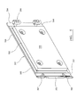
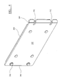
- door 203 comprises an inward facing surface 504 to be orientated towards opening 207 and an external facing surface 600 orientated away from opening 207.
- Door 203 comprises a substantially planar rectangular geometry in which hinge and lock edges 204, 205 are shorter in length than length edges 506. The dimensions of door 203 correspond approximately to the dimensions of frame 200 that defines the rectangular opening 207.
- a sealing gasket 503 extends around a perimeter region of surface 504 to provide a seal as door 203 is closed against frame 200. Additionally, a mounting plate 505 is secured to door surface 504 and is dimensioned so as to fit within frame walls 201, 202 when door 203 is in the closed hatch position. Plate 505 and sealing gasket 503 may comprise a resiliently deformable material so as to provide a sealing contact against frame 200. The second half of horizontal mechanism 208 extends from door face 504 towards hinge edge 204.
- the substantially planar door 203 is curved towards lock edge 205 along the edge length.
- a pair of slots 502 extends inwardly from the lock edge of door 203 a short distance in the direction of length edge 506. This curved region 501 defines a handle part of door 203.
- the exposed substantially planar face 500 of plate 505 occupies opening 207 such that hatch 100 is closed.
- the door 203 is maintained in the hatch closed position by lock bodies 206 engaging with slots 502 to prevent door 203 pivoting via hinge mechanism 208 to the door open position.
- a second half of the hinge mechanism 208 comprises a bolt having a bolt axle 702 and a bolt head 700 at one end.
- a spacer collar 701 extends around axle 702 and extends a distance along the length of axle 702.
- a barrel 703 comprises a generally cylindrical geometry and is connected to axle 702.
- body 805 comprises barrel 703 having a longitudinal axis 803 aligned perpendicular to a longitudinal axis 804 of axle 702.
- a securing pin 801 extends through one end of axle 702 via a through bore 800. Pin 801 is positioned at a second end of axle 702 whilst head 700 is positioned at the opposite first end. Additionally, pin 801 comprises a longitudinal axis 900 aligned perpendicular to axis 804.
- Axle 702 extends through the body of barrel 703 via a through bore 802. Collar 701, extending around axle 702, is positioned between head 700 and barrel 703. Axle 702 is capable of advancing and retracting through barrel 702 via cooperation of corresponding screw threads (not shown) formed on an external surface of axle 702 and formed internally within bore 802. Accordingly, axle 702 may be screwed through barrel 703 via head 700. Axle 702 is prevented from detachment from barrel 703 by virtue of head 700 comprising a greater radial diameter than bore 802 and pin 801 that projects beyond bore 800 such that a length of pin 801 is greater than the diameter of bore 802.
- each hinge mechanism 208 is interchangeable in that body 805 is located at all four hinge mounts 300 (created by arms 301 and apertures 302) and is capable of functioning as a part of a hinge or a lock mechanism. That is, according to one embodiment the lock body 206 comprises the same arrangement and components as the body 805 including in particular axle 702, pin 801, barrel 703, collar 701 and head 700. According to further embodiments, the hinge body does not comprise pin 801 and comprises an axel 702 that is shorter in length than the corresponding length of axle 702 of the lock body 206.
- Each barrel 703 is dimensioned so as to sit within apertures 302 of each pair of arms 301. Accordingly, the longitudinal axis 803 of barrel 703 is aligned parallel to vertical walls 201.
- Body 805 is secured to door 203 at its hinge edge 204 as shown in figure 7 as axle 702 passes through the door body and is secured in position by head 700 clamping against external surface 600.
- Axle 702 and accordingly door 203 is therefore supported by each respective pair of arms 301 and is capable of pivoting about longitudinal axis 803 of both barrels 703 to allow door 203 to swing to and fro at frame wall 201.
- axle 702 towards head 700 is capable of pivoting into each respective slot 502 as door 203 is brought to the hatch closed position.
- each head 700 may be rotated to clamp against a region of external surface 600 to lock the door 203 in the closed position.
- the door 803 may be secured and hingeably mounted at either side wall 201 by simply removing bolts 700, 702, rotating door 203 through 180° and reattaching the door via its hinge edge 204 at the opposite set of mounts 300 at the opposite frame wall 201.
- the present hatch is configured to be both left and right hand opening.
- the lock mechanism is also capable of actuation at either the right or left wall 201.
- the present hatch comprises four pivotally mounted bodies 805 secured at each four hinge mounts 301 with the bodies 805 acting as either the hinge mechanism or the lock mechanism by interchanging the respective bolts (700, 702). As bodies 805 are retained in position at each mount 300, door 203 may be conveniently interchanged between left and right hand opening by adjustment of heads 700 using an appropriate tool (not shown).
Landscapes
- Engineering & Computer Science (AREA)
- Food Science & Technology (AREA)
- Mechanical Engineering (AREA)
- Disintegrating Or Milling (AREA)
- Hinges (AREA)
- Crushing And Pulverization Processes (AREA)
Priority Applications (11)
| Application Number | Priority Date | Filing Date | Title |
|---|---|---|---|
| EP12179087.7A EP2692443A1 (fr) | 2012-08-02 | 2012-08-02 | Trappe de trémie de concassage |
| PCT/EP2013/062864 WO2014019766A1 (fr) | 2012-08-02 | 2013-06-20 | Ouverture de trémie pour l'alimentation d'un broyeur |
| AU2013298872A AU2013298872A1 (en) | 2012-08-02 | 2013-06-20 | Crusher feed hopper hatch |
| BR112015002170A BR112015002170A2 (pt) | 2012-08-02 | 2013-06-20 | escotilha de funil de alimentação de triturador |
| US14/418,558 US20150196922A1 (en) | 2012-08-02 | 2013-06-20 | Crusher feed hopper hatch |
| CA2879433A CA2879433A1 (fr) | 2012-08-02 | 2013-06-20 | Ouverture de tremie pour l'alimentation d'un broyeur |
| RU2015106979A RU2015106979A (ru) | 2012-08-02 | 2013-06-20 | Люк загрузочного бункера дробилки |
| CN201380041192.4A CN104582852A (zh) | 2012-08-02 | 2013-06-20 | 破碎机进料斗舱口 |
| CN201320444825.3U CN203635300U (zh) | 2012-08-02 | 2013-07-24 | 粉碎机进料料斗舱口盖、粉碎机料斗和粉碎机 |
| CN201310314172.1A CN103567047A (zh) | 2012-08-02 | 2013-07-24 | 粉碎机进料料斗舱口盖 |
| CL2015000204A CL2015000204A1 (es) | 2012-08-02 | 2015-01-27 | Compuerta de tanque para trituradora de alimento |
Applications Claiming Priority (1)
| Application Number | Priority Date | Filing Date | Title |
|---|---|---|---|
| EP12179087.7A EP2692443A1 (fr) | 2012-08-02 | 2012-08-02 | Trappe de trémie de concassage |
Publications (1)
| Publication Number | Publication Date |
|---|---|
| EP2692443A1 true EP2692443A1 (fr) | 2014-02-05 |
Family
ID=46750186
Family Applications (1)
| Application Number | Title | Priority Date | Filing Date |
|---|---|---|---|
| EP12179087.7A Withdrawn EP2692443A1 (fr) | 2012-08-02 | 2012-08-02 | Trappe de trémie de concassage |
Country Status (9)
| Country | Link |
|---|---|
| US (1) | US20150196922A1 (fr) |
| EP (1) | EP2692443A1 (fr) |
| CN (3) | CN104582852A (fr) |
| AU (1) | AU2013298872A1 (fr) |
| BR (1) | BR112015002170A2 (fr) |
| CA (1) | CA2879433A1 (fr) |
| CL (1) | CL2015000204A1 (fr) |
| RU (1) | RU2015106979A (fr) |
| WO (1) | WO2014019766A1 (fr) |
Families Citing this family (5)
| Publication number | Priority date | Publication date | Assignee | Title |
|---|---|---|---|---|
| EP2692443A1 (fr) * | 2012-08-02 | 2014-02-05 | Sandvik Intellectual Property AB | Trappe de trémie de concassage |
| USD745572S1 (en) * | 2012-11-14 | 2015-12-15 | Sandvik Intellectual Property Ab | Crusher feed hopper wear protection cassette |
| CN105414850B (zh) * | 2015-12-24 | 2017-10-31 | 中铁十九局集团第七工程有限公司 | 定位辅助框架 |
| US11534769B2 (en) * | 2018-01-31 | 2022-12-27 | Sandvik Srp Ab | Gyratory crusher bottomshell with inspection hatch assembly |
| CN115155717B (zh) * | 2022-07-05 | 2024-03-29 | 合肥综合性国家科学中心能源研究院(安徽省能源实验室) | 一种煤基固废填充用破碎混合装置 |
Citations (10)
| Publication number | Priority date | Publication date | Assignee | Title |
|---|---|---|---|---|
| WO1980000128A1 (fr) * | 1978-07-05 | 1980-02-07 | Metal Box Co Ltd | Machines a dechiqueter |
| GB2101659A (en) * | 1981-07-07 | 1983-01-19 | Lomazzo Costr Mecc | Hatch cover mountable in alternative positions |
| GB2301097A (en) * | 1995-05-26 | 1996-11-27 | Lamberton & Co Ltd | Anti-Bridging Chute Assembly |
| WO2004020103A1 (fr) | 2002-08-28 | 2004-03-11 | Sandvik Intellectual Property Hb | Broyeur et procede de broyage d'une matiere |
| US20040211849A1 (en) * | 2001-09-03 | 2004-10-28 | Hitoshi Itoh | Raw feed feeding device of jet mill |
| WO2004110626A1 (fr) | 2003-06-18 | 2004-12-23 | Sandvik Intellectual Property Ab | Procede et dispositif pour fixer une coque de broyeur |
| EP1903102A1 (fr) * | 2006-09-25 | 2008-03-26 | Huning Maschinenbau GmbH | Dispositif destiné au transport de matériaux de biomasse |
| WO2010042025A1 (fr) | 2008-10-08 | 2010-04-15 | Sandvik Intellectual Property Ab | Dispositif d’alimentation en matériau pour broyeur vsi et procédé de broyage de matériau |
| WO2010123431A1 (fr) | 2009-04-22 | 2010-10-28 | Sandvik Intellectual Property Ab | Broyeur giratoire, coque externe destinée à ce broyeur et procédés de montage et de démontage de la coque externe |
| WO2012005651A1 (fr) | 2010-07-09 | 2012-01-12 | Sandvik Intellectual Property Ab | Broyeur giratoire à agencement d'étanchéité |
Family Cites Families (4)
| Publication number | Priority date | Publication date | Assignee | Title |
|---|---|---|---|---|
| US4151681A (en) * | 1977-12-01 | 1979-05-01 | General Electric Company | Arrangement for mounting hinge pin sockets to cabinet doors |
| FI109662B (fi) * | 2001-08-31 | 2002-09-30 | Metso Minerals Tampere Oy | Siirrettävän murskausyksikön tärysyöttimen kuljetuslukitus |
| CN102582789A (zh) * | 2011-01-05 | 2012-07-18 | 高邮市长城机械制造有限公司 | 一种桥墩防撞装置的舱口盖 |
| EP2692443A1 (fr) * | 2012-08-02 | 2014-02-05 | Sandvik Intellectual Property AB | Trappe de trémie de concassage |
-
2012
- 2012-08-02 EP EP12179087.7A patent/EP2692443A1/fr not_active Withdrawn
-
2013
- 2013-06-20 WO PCT/EP2013/062864 patent/WO2014019766A1/fr not_active Ceased
- 2013-06-20 BR BR112015002170A patent/BR112015002170A2/pt not_active IP Right Cessation
- 2013-06-20 AU AU2013298872A patent/AU2013298872A1/en not_active Abandoned
- 2013-06-20 RU RU2015106979A patent/RU2015106979A/ru not_active Application Discontinuation
- 2013-06-20 CA CA2879433A patent/CA2879433A1/fr not_active Abandoned
- 2013-06-20 US US14/418,558 patent/US20150196922A1/en not_active Abandoned
- 2013-06-20 CN CN201380041192.4A patent/CN104582852A/zh active Pending
- 2013-07-24 CN CN201310314172.1A patent/CN103567047A/zh active Pending
- 2013-07-24 CN CN201320444825.3U patent/CN203635300U/zh not_active Expired - Fee Related
-
2015
- 2015-01-27 CL CL2015000204A patent/CL2015000204A1/es unknown
Patent Citations (10)
| Publication number | Priority date | Publication date | Assignee | Title |
|---|---|---|---|---|
| WO1980000128A1 (fr) * | 1978-07-05 | 1980-02-07 | Metal Box Co Ltd | Machines a dechiqueter |
| GB2101659A (en) * | 1981-07-07 | 1983-01-19 | Lomazzo Costr Mecc | Hatch cover mountable in alternative positions |
| GB2301097A (en) * | 1995-05-26 | 1996-11-27 | Lamberton & Co Ltd | Anti-Bridging Chute Assembly |
| US20040211849A1 (en) * | 2001-09-03 | 2004-10-28 | Hitoshi Itoh | Raw feed feeding device of jet mill |
| WO2004020103A1 (fr) | 2002-08-28 | 2004-03-11 | Sandvik Intellectual Property Hb | Broyeur et procede de broyage d'une matiere |
| WO2004110626A1 (fr) | 2003-06-18 | 2004-12-23 | Sandvik Intellectual Property Ab | Procede et dispositif pour fixer une coque de broyeur |
| EP1903102A1 (fr) * | 2006-09-25 | 2008-03-26 | Huning Maschinenbau GmbH | Dispositif destiné au transport de matériaux de biomasse |
| WO2010042025A1 (fr) | 2008-10-08 | 2010-04-15 | Sandvik Intellectual Property Ab | Dispositif d’alimentation en matériau pour broyeur vsi et procédé de broyage de matériau |
| WO2010123431A1 (fr) | 2009-04-22 | 2010-10-28 | Sandvik Intellectual Property Ab | Broyeur giratoire, coque externe destinée à ce broyeur et procédés de montage et de démontage de la coque externe |
| WO2012005651A1 (fr) | 2010-07-09 | 2012-01-12 | Sandvik Intellectual Property Ab | Broyeur giratoire à agencement d'étanchéité |
Also Published As
| Publication number | Publication date |
|---|---|
| CL2015000204A1 (es) | 2015-10-23 |
| CN104582852A (zh) | 2015-04-29 |
| CA2879433A1 (fr) | 2014-02-06 |
| CN103567047A (zh) | 2014-02-12 |
| RU2015106979A (ru) | 2016-09-20 |
| AU2013298872A1 (en) | 2015-02-05 |
| US20150196922A1 (en) | 2015-07-16 |
| BR112015002170A2 (pt) | 2018-11-13 |
| CN203635300U (zh) | 2014-06-11 |
| WO2014019766A1 (fr) | 2014-02-06 |
Similar Documents
| Publication | Publication Date | Title |
|---|---|---|
| EP2692443A1 (fr) | Trappe de trémie de concassage | |
| CN109551043B (zh) | 拆除剪及拆除剪的刺尖插件和端头部配件 | |
| JP5749899B2 (ja) | ハンマー粉砕装置 | |
| CN113499826A (zh) | 一种偏心辊式破碎机 | |
| US20160107164A1 (en) | Closure System For Ball Mills And Method For Opening And Closing Ball Mills | |
| US20100078511A1 (en) | Star feeder with comminuting insert | |
| US9469491B2 (en) | Rotary feeder | |
| JP4431463B2 (ja) | 粉砕機 | |
| US4175710A (en) | High performance shredder apparatus | |
| JP4503684B2 (ja) | 粉砕機 | |
| CN101708479B (zh) | 一种自动开闭的破磨机壳体 | |
| EP2789390A1 (fr) | Trappe d'inspection de broyeur | |
| KR20190000425U (ko) | 분쇄기 | |
| JP3302601B2 (ja) | 横型粉砕機 | |
| JP4524329B2 (ja) | 粉砕機 | |
| CN215197259U (zh) | 机箱装置及破碎机 | |
| JP2009078270A (ja) | 粉砕機 | |
| CN218742338U (zh) | 一种城市垃圾回收前处理设备 | |
| CN220258300U (zh) | 一种矿渣粉磨机进料口防粘堵机构 | |
| CN118925881A (zh) | 一种粉碎机 | |
| CN221016421U (zh) | 一种粉料粉碎装置 | |
| EP1655073B1 (fr) | Broyeur pour des matériaux inertes et/ou recyclés avec fermeture basculante | |
| CN220160149U (zh) | 一种超细粉磨机内的阻流装置 | |
| CN217346224U (zh) | 一种废旧塑料用粉碎机 | |
| EP3746228B1 (fr) | Coque inférieure de broyeur giratoire, dotée d'ensemble trappe de visite |
Legal Events
| Date | Code | Title | Description |
|---|---|---|---|
| AK | Designated contracting states |
Kind code of ref document: A1 Designated state(s): AL AT BE BG CH CY CZ DE DK EE ES FI FR GB GR HR HU IE IS IT LI LT LU LV MC MK MT NL NO PL PT RO RS SE SI SK SM TR |
|
| AX | Request for extension of the european patent |
Extension state: BA ME |
|
| PUAI | Public reference made under article 153(3) epc to a published international application that has entered the european phase |
Free format text: ORIGINAL CODE: 0009012 |
|
| 17P | Request for examination filed |
Effective date: 20140805 |
|
| RBV | Designated contracting states (corrected) |
Designated state(s): AL AT BE BG CH CY CZ DE DK EE ES FI FR GB GR HR HU IE IS IT LI LT LU LV MC MK MT NL NO PL PT RO RS SE SI SK SM TR |
|
| 17Q | First examination report despatched |
Effective date: 20141215 |
|
| GRAP | Despatch of communication of intention to grant a patent |
Free format text: ORIGINAL CODE: EPIDOSNIGR1 |
|
| RIC1 | Information provided on ipc code assigned before grant |
Ipc: B02C 23/02 20060101ALI20150910BHEP Ipc: B02C 2/00 20060101ALI20150910BHEP Ipc: B02C 13/286 20060101AFI20150910BHEP |
|
| INTG | Intention to grant announced |
Effective date: 20150930 |
|
| GRAS | Grant fee paid |
Free format text: ORIGINAL CODE: EPIDOSNIGR3 |
|
| GRAL | Information related to payment of fee for publishing/printing deleted |
Free format text: ORIGINAL CODE: EPIDOSDIGR3 |
|
| STAA | Information on the status of an ep patent application or granted ep patent |
Free format text: STATUS: THE APPLICATION IS DEEMED TO BE WITHDRAWN |
|
| 18D | Application deemed to be withdrawn |
Effective date: 20160211 |